Transcription
BASIC HYDRAULIC PRINCIPLESOF OPEN-CHANNEL FLOWBy Harvey E. Jobson and David C. FroehlichU.S. GEOLOGICAL SURVEYOpen-FileReport88-707Reston, Virginia1988
DEPARTMENT OF THE INTERIORDONALD PAUL HODEL, SecretaryU.S. GEOLOGICAL SURVEYDallas L. Peck, DirectorFor additional informationwrite to:Copies of this report can bepurchased from:Chief, Office of Surface WaterU.S. Geological Survey415 National Center12201 Sunrise Valley DriveReston, Virginia 22092U.S. Geological Survey, Booksand Open-File ReportsBox 25425, Federal CenterDenver, Colorado 80225
CONTENTSPageAbstract .Introduction .Part I - Basic principles of hydraulics for an ideal fluid .Lesson 1 - Fluid properties .Lesson 2 - Forces on submerged objects .Lesson 3 - Similitude and dimensional analysis .Lesson 4 - The energy equation for an ideal fluid .Part II - Steady uniform flow of real fluids in open channels .Lesson 5 - Velocity profiles .Lesson 6 - The energy equation applied to real fluids .Lesson 7 - Flow resistance .Lesson 8 - Computations for steady, uniform flow .Part III - Advanced principles of steady flow .Lesson 9 - Flow in channel sections with variable roughness .Lesson 10 - The momentum principle .Lesson 11 - Specific energy .Part IV - Gradually varied flow in open channels .Lesson 12 - Determination of flow resistance in open channels .Lesson 13 - Classification of water-surface profiles .Lesson 14* - Local energy losses in natural channels .Lesson 15 - Water-surface profile computations .Part V - Discharge computations for rapidly varied flow .Lesson 16 - Rapidly varied flow at constrictions .Lesson 17 - Flow through culverts .Lesson 18 - Flow over weirs .References .Answers to problems 32145147ILLUSTRATIONSPageFigure 1-1.2-1.2-2.2-3.3-1.4-1.4-2.4-3.5-1.5-2.Free body diagram of fluid element .Definition sketch of the pressure prism for verticalrectangular gate .Definition sketch of the pressure prism for a submergedgate 4 feet wide .Definition sketch of the pressure prism to compute thetotal force of the water on a 4-foot wide gate .Diagram illustrating flow through constriction, model, andprototype .Definition sketch of steady flow through a streamtube .Definition sketch for the flow of an ideal fluid in an openchannel .Definition sketch for the example problem of flow down aramp .Definition sketch for sheet flow over a wide inclined planeof width W .Diagram illustrating velocity distribution in a fullydeveloped, rough turbulent flow .11138910172828303538
ILLUSTRATIONSPageFigure .17-3.18-1.18-2.18-3.18-4.18-5.18-6.Definition sketch of the energy diagram for open-channelflow .Diagram illustrating typical flow through a bridgeconstriction .Diagram illustrating flow in a prismatic open channel .Definition sketch for cross section with overbank flow .Diagram illustrating the control volume for applying theconservation of momentum equation for the flow past apier .Definition sketch for the specific energy curve .Diagram illustrating flow changes from subcritical tosupercritical .Diagram illustrating critical flow at the outlet of a boxculvert .Diagram illustrating eight types of roughness found insand-bed channels .Diagram illustrating the effect of size of bed materialand Froude number on the bed form and Manning's n fora range of flow conditions with sands of 0.28- and0.45-millimeter median diameter in an 8-foot wideflume .Graph showing the relation of stream power and mediangrain size to the bed form .Sketch illustrating gradually varied flow in an openchannel longitudinal scale greatly reduced .Definition sketch of surface profiles of varied flow .Sketch illustrating the energy grade lines at a localobstruction .Definition sketch for water-surface profile computation .Graph showing the variation of friction slope withdistance along the channel .Sketch illustrating the theoretical water-surface andenergy profiles through a contracted opening .Sketch illustrating the streamlines for flow through asharp-edged opening .Graph showing the coefficients for type 1 opening,vertical embankments, and vertical abutments .Definition sketch of culvert flow .Diagram illustrating the classification of culvert flow .Graph showing the base coefficient of discharge fortypes I, 2, and 3 flow in box culverts with squareentrance mounted flush in vertical headwall .Definition sketch for a contracted, sharp-crested weir .Definition sketch for a broad-crested weir .Graph showing the coefficients of discharge for fullwidth, broad-crested weirs with downstream slope 1:1,and various upstream slopes .Definition sketch of a V-notch (triangular) sharp-crestedweir .Definition sketch of a Cippoletti (trapezoidal)sharp-crested weir .Diagram illustrating various other sharp-crested weirprofiles 125127132132134137139139
TABLESPageTable 1-1.6-1.Mechanical properties of some fluids .Kinetic energy correction coefficients for naturalchannels .Values of the Manning resistance coefficient .Equations for resistance based on bed-material size .44869112-3.Sediment grade scale .9215-1.15-2.17-1.Criteria used to select friction slope equation . 110Computation sheet for backwater analysis . 112Discharge coefficients for box or pipe culverts setflush in a vertical headwall; types 4 and 6 flow . 12912-1.12-2.4
UNIT CONVERSIONData listed in this report are defined in the inch-pound system of units.A list of these units and the factors for their conversion to InternationalSystem of units (SI) are provided below.Abbreviations of units are defined in the conversion table below or wherethey first appear in the text. Symbols are defined where they first appear inthe text.Multilinch-ound unitfoot (ft)inch (in)pound (Ib)slugslug per cubic foot (slug/ft 3 )slug per foot second(slug/s ft)pound per cubic foot (lb/ft 3 )pound per square foot (lb/ft 2 )square foot per second (ft 2 /s)pound per square inch (lb/in 2 )pound per cubic inch (lb/in 3 )pound per inch (Ib/in)pound second per square foot(Ib s/ft 2 )foot per square second (ft/s 2 )cubic foot per second (ft 3 /s)degree Fahrenheit ( F)To obtain SI 92906,895271,400175.147.880.30480.028323C F-32)/l.meter (m)meter (m)newton (N)kilogram (kg)kilogram per cubic meter(kg/m3 )newton per meter second(N/m2 )newton per cubic meter (N/m3 )pascal (Pa)square meter per second (m2 /s)pascal (Pa)newton per cubic meter (N/m3 )newton per meter (N/m)pascal second (Pa s)meter per square second (m/s 2 )cubic meter per second (m3 /s)degree Celsius ( C)SYMBOLS AND otal area of a sectionTotal cross-section area at the cross-section number iArea of a subsection iWidth of openingWidth of channel upstream of openingChezy resistance coefficientDepthBrink depthCritical depthNormal depthDiameter or height of a culvertDepth in overflow sectionParticle size that is larger than p percent of the bedmaterialSpecific energyForceft'2ft 2ft 2ftftftl/2/sftftftftftftftVIftIb
SymbolFHFRF RQrSSeSfSgS0Ttu VVcvWExplanationHorizontal forceResultant forceDrag forceWater-pressure forceFroude numberVertical forceShear forceDarcy-Weisbach friction factorAcceleration of gravityTotal headHydraulic (piezometric) headHead loss due to local causesHead loss due to boundary frictionHead loss due to any causeTail-water elevationVelocity headAccelerationConveyanceTotal conveyance at cross-section number iEffective roughness height of boundaryExpansion or contraction loss coefficientConveyance at subsection iLocal loss coefficientDistance along channel or length of structureLength scale for Reynolds number or Prandtl's mixinglengthThe meander length of a channel reachThe straight length of a channel reachMassChannel contraction ratioManning's roughness factorWetted perimeter of channel or height of weirPressurePressure at the center of pressureDischargeDischarge per unit widthHydraulic radiusReynolds numberRadius of curvatureSlopeSlope of energy grade lineFriction slopeSpecific gravity of fluidSlope of bedTop width of the channelTimeShear velocityAverage or mean velocityCritical velocityLocal velocityWidthVIIUnitIbIbIbIbIbIbft/s ftftftftftftftft/s ft /sft 'sftft /sftftftftslugftft /sft /sftftftsft/sft/sft/sft/sft
SymbolW0wtxyyrZzaYAEAh0KJl\)pTTOExplanationWidth of overflow sectionWeight of waterHorizontal coordinate directionVertical coordinate directionDepth to center of pressureElevationDistance from datum to culvert invertKinetic energy coefficient or Cariolis coefficientSpecific weight of the fluidEnergy lossChange in water-surface elevationSlope angle of bed or angle of V-notch weirvon Karman constantDynamic viscosityKinematic viscosityDensity of the fluidShear stressShear stress at the bedUnitftIbftftftftftlb/ft 3ftftIb s/ft 2 , slug/s ftft 2 /sslugs/ft 3lb/ft 2lb/ft 2
BASIC HYDRAULIC PRINCIPLES OF OPEN-CHANNEL FLOWby Harvey E. Jobson and David C. FroehlichABSTRACTThe three basic principles of open-channel-flow analysis the conservation of mass, energy, and momentum are derived, explained, and applied tosolve problems of open-channel flow. These principles are introduced at alevel that can be comprehended by a person with an understanding of the principles of physics and mechanics equivalent to that presented in the firstcollege level course of the subject. The reader is assumed to have a workingknowledge of algebra and plane geometry as well as some knowledge of calculus.Once the principles have been derived, a number of example applicationsare presented that illustrate the computation of flow through culverts andbridges, and over structures, such as dams and weirs.Because resistance to flow is a major obstacle to the successful application of the energy principle to open-channel flow, procedures are outlinedfor the rational selection of flow-resistance coefficients. The principle ofspecific energy is shown to be useful in the prediction of water-surfaceprofiles both in the qualitative and quantitative sense.INTRODUCTIONMost of the principles and concepts presented in a beginning levelcollege course in fluid mechanics are presented herein, but their applicationis focused on open-channel hydraulics. Some concepts that are unique to openchannels for example, specific energy and channel roughness are developed insomewhat more detail here than would be expected in an introductory collegecourse.It is assumed that the reader is familiar with the physical principlesof mechanics, at least to the level covered by a beginning college physicsbook. The reader also is assumed to have a working knowledge of algebra andtrigonometry and to comprehend simple derivatives and integrations.The emphasis of this text is on teaching the application of the theoryof hydraulics to solving practical problems and not on the standard techniquesused in problem solutions. The final equations developed in this text arefrequently used as the starting point in other chapters of Book 3 of theTechniques of Water-Resources Investigations of the U.S. Geological Survey.Manuscript approved for publication November 17, 1988
PART I - BASIC PRINCIPLES OF HYDRAULICS FOR AN IDEAL FLUIDLesson 1 - Fluid PropertiesAll quantities used in this report can be defined in terms of threebasic units (length (foot), time (second), and mass (slug)). Another quantitythat is commonly used is force (pound), but the units of this quantity aredefined in terms of mass and acceleration.The weight on earth (force) of a mass of one slug is defined to be 32.2pounds (Ib). Therefore, the units of pounds force are equivalent to the unitsof slug feet per second squared (slug ft/s ) orForce F 32.2 Ib Mg (1 slug) 32.2 ft/s 2 ,where the mass of the body is M, and g is the acceleration of gravity (32.2ft/s 2 ) .Because fluid does not have a definite form and specific particles offluid are difficult to identify, it is customary to work with the weight ormass of fluid per unit volume. The mass of a fluid per unit volume is definedas its density (p) :Density p Mass of fluid (slugs) .Volume of fluid (ft j )The specific (unit) weight of a fluid 7 is defined as:. , y Weightof fluid (Ib)Specific weight*r .Volume of fluid (ft 3 )The specific gravity of a fluid is defined as the ratio of the densityof the fluid to the density of water at standard conditions (1.94 slugs/ft 3 )that is,. ,. Gravity.3)Specific Sg density of fluid (slugs/ftT density of water (slugs/ft-3 )Because it is a ratio, specific gravity is unitless. By multiplying both thenumerator and the denominator of the expression for the specific gravity by g,it is seen that the specific gravity also is equal to the ratio of specificweights, Kf ft3 j* 'o ,Sg Pw " nI slug ft\, f ft3 " s2Jfsluc g (ft/32, y(-L- slug, ft Yf(lb/ft3)Yw db/ft 3 );2in which the subscripts f and w refer to the fluid and water, respectively. Afluid is a substance that can flow. Specifically, this means that it continually deforms as long as a shearing stress is applied and that the internalshear stress is a function of the rate of deformation rather than the amountof deformation as in a solid. A Newtonian fluid is a substance in which theinternal shear stress is determined as
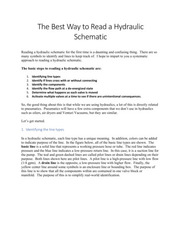
(1-Din which T is the shear stress (lb/ft 2 ), 3v is the change in velocity (ft/s)s Ibthat occurs over a small distance 3y (ft), and the dynamic viscosity \i ft 2 oris a specific fluid property, which is a measure of its resistance tos ftdeformation (shear or flow). Table 1-1 contains some tabulated viscosities offluids and gases. The kinematic viscosity V is defined asV U Sluq/S ftft 2sp slug/ft 3Figure 1-1 shows a free body diagram of an isolated block of fluid ofheight y, width dx, and thickness of 1 foot. Figure 1-1 is called a free-bodydiagram. A free-body diagram is a cutaway view of the fluid or object inwhich the effect of any surface that is cut is replaced by the forces exertedon that surface. For example, the bottom surface could exert a shear force(Tdx(l)) on the fluid and a pressure force (pdx(l)). These are the onlyforces the water beneath could exert on the block of fluid. The fluid is atrest, therefore, all shear stresses (T) are zero (see equation 1-1).Figure 1-1. Free-body diagram offluid element.dxThe pressure (p) at the bottom of the block in figure 1-1 can be computed as follows. Because the sides are vertical and the shear stress iszero, the weight (wt) is balanced by the pressure at the bottom times the areaof the bottom of the block orwt pdx(1) ,but the weight iswt YVolume y ydx(l)oryydx(l) pdx(l) ;thereforep y y.which shows that in a fluid at rest, the pressure increases linearly withdepth below the surface.(1-2)
Table 1-1. Mechanical properties of some fluids[ft 3 , cubic foot; lb/ft 3 , pounds per cubic foot; s Ib, second times pound; F, degrees Fahrenheit](A) Some properties of air at atmospheric pressureTemperature F04080120Densityslug/ft 3PSpecific weightlb/ft nematic viscosityft 2 /sV12.614.616.918.9xxxx10 510 510 510 5(B) Mechanical properties of water at atmospheric pressureTemperature F32405060708090100120Densityslug/ft 3PSpecific weightlb/ft 62.462.362.262.162.061.7Dynamic viscositys lb/ft 2H3.753.242.742.362.041.801.591.421.17xxxxxxxxx10 510 510 510 510 510 510 510 510 5
Table 1-1.--Mechanical properties of some fluids continued(C) Specific gravity and kinematic viscosity of certain liquids(Kinematic viscosity tabular value x 10" )Temperature F406080100Temperature FCarbon tetrachlorideKinematicSpecificviscosityft 2 00.905.896.888.882Medium fuel oilKinematicSpecificviscosityft 2 /sgravityVSg406080100Mediumlubricatincr oilKinematicSpecificviscosityft 2 /sgravity0.865.858.851.843V4771889449.2Regular gasolineKinematicSpecificviscositygravityft 2 0.600(D) Specific gravity and kinematic viscosity of someother liquidsLiquid and temperatureSpecificgravityKinematicviscosityft 2 /sVTurpentine at 68 FLinseed oil at 86 FEthyl alcohol at 68 FBenzene at 68 FGlycerin at 68 FCastor oil at 68 FLight machinery oil at 111,110147
PROBLEMS1.2.Compute your mass in slugs.The density of alcohol is 1.53 slugs/ft .and specific gravity.Calculate its specific weight
3.A stream gager falls in the river and gets his boots full of water. Hemanages to get to shore but his boots are still full of water. What isthe maximum pressure inside his boots when he stands up? His boots are 3feet high.3 ft4.The inside of a pipe, which has an inside diameter of 6 inches, is coatedwith heavy oil. A 2-lb cylinder 6 inches long and 5.98 inches in diameter falls through the vertical pipe at a rate of 0.15 ft/s. Calculatethe dynamic viscosity of the oil.
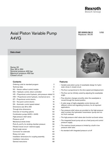
Lesson 2 - Forces on Submerged ObjectsOnly fluids at rest will be dealt with in this lesson so no tangential(shear) forces are exerted, and hence all forces are normal to the free bodysurfaces in question. Consider the force on a vertical rectangular gate asillustrated in figure 2-1. As seen from equation 1-2, the pressure increaseswith increasing distance below the water surface; hence, the force (dF) on anarrow strip of the gate of height dy and width W is computed asFigure 2-1. Pressure prism forvertical rectangulargate.The total force on the vertical surface may be computed as the sum ofall of the differential force values (dF on fig. 2-1). Hence, the total horizontal force on the surface isF JJdF Wy dy (2-1)AAnother technique to compute the force is based on the fact that theforce is equal to the volume of the pressure prism defined by the solid abcdefin figure 2-1. The force on any submerged surface is equal to the volume ofthe pressure prism. The pressure prism is the solid with a base equal to thearea of the surface in contact between the gate and the water and with aheight equal to the pressure on the surface. It is often easier to visualizethe pressure prism and compute its volume than to integrate an expression suchas the equation for dF. For example, the pressure prism in figure 2-1 is asolid of triangular shape and width W. The area of the base is the area ofthe triangle with one side equal to D and the other side equal to "YD. Forcomplex shapes it is usually possible to break up the pressure prism intosimpler geometric shapes and compute the volume of each simple shape. Thetotal force is then the sum of the volumes.A third way to visualize the force on a surface is that it is equal topressure at the centroid of the wetted area (called the center of pressure,Cp, see fig. 2-1) times that area. The total force on an object can always becorrectly computed using this approach also. On figure 2-1 the wetted area is
a rectangle (bcfe), which has its centroid at D/2 feet below the surface. Theforce is thereforeF pc A Cyo/2)(DW) .Example:As an example, the horizontal and vertical components of the force ofthe water on the 4-foot wide gate shown in figure 2-2 will be computed. Thepressure prism for the horizontal force is shown on the figure with a heightdefined by a b c d a and a base of 4 feet by 8 feet.Watersurface4 feetFigure 2-2. Pressure prism for asubmerged gate 4 feetwide.Solution :The volume of the pressure prism may be obtained by breaking it into atriangle with sides of 8ylb/ft 2 and 8 feet and a rectangle with sides of4ylb/ft 2 and 8 feet. The total horizontal force, FH , of the water on thevertical plane c d x 4 feet is then computed as the sum of these two volumes 8Y (8) (4) 4y (8) (4) 256y 15, 974 lb.The fluid force on this plane is the same as the horizontal component of theforce of the water on the gate because there are no shear stresses when thefluid is at rest.The vertical force of the water, Fv, on the plane d e x 4 feet iscomputed from the volume of the pressure prism defined by the points d e f q dand the 4-foot width.Fv 12y (7) (4) 336y 20,966 lb.This force supports the weight of the water in the volume c d e c x 4 feet;the balance being the force exerted on the gate. The vertical force of thewater on the gate is thereforeFv [12y(7)(4)] - [ 8/2)y (7) (4)] 13,9781b.
The vertical component of force on any area is equal to the weight ofthat volume of fluid that would extend vertically from the area to the freesurface. As a result of this, the buoyant force on any object is equal to theweight of the water displaced.The total resultant force isFR FH 2 340.2y 21,226 Ib.Another way to compute the resultant force is to draw the pressure prismas shown in figure 2-3. This time the force on the surface b c will be computed directly and it should be the resultant force on the gate. As before,it is natural to break the pressure prism into a triangle with sides 8ylb/ft 2and 10.63 feet and a rectangle with sides of 4ylb/ft 2 and 10.63 feet. Noticeone side is 10.63 feet long in this case rather than 8 feet long when lookingat only the horizontal component. The volume of the pressure prism isF R - (10.63)4 4y(10.63)4 340.27 21,226 Ib,which is the same result as obtained above.Figure 2-3.--Pressure prism to computethe total force of thewater on a 4-foot widegate.Forces not only have a magnitude and direction but a line of action aswell. The line of action is the location where a single resultant force mustbe applied to have the same effect on a body as the distributed forces itreplaces. For example, the center of gravity of a solid body is the pointwhere a single force must be applied to the body to counter its weight withoutcausing a torque (or moment) on the body.Consider the line of action of the resultant pressure force on thesurface in figure 2-1. The resultant force F must act at a point such thatits moment (or torque) about any point is equal to the sum of the moments ofeach small force dF. Sum the moments about the line b-e and set them equal toF times yr to determine the distance of the line of action of the resultantforce below the water surface10
F yr (yWD 2 /2) (yr ) y dF ywJoy2 dy yWD 3 /3Jofrom whichy r 2/3 D.(2-3)Notice the line of action is through the center of gravity of the pressureprism abcdef . This will always be the case. Complex pressure prisms canusually be subdivided into simpler shapes for which the center of gravity canbe easily determined. The resultant line of action is then obtained bysumming the moments of each subvolume about a convenient reference point.Example :Compute the location of the resultant force of the water on the gateshown in figure 2-3.Solution:The location of the force due the rectangular part of the pressure prism(FR- ) in figure 2-3 is located 5.32 feet from the top of the gate. The resultant force, FR2' due to the triangular part of the pressure prism is located7.09 feet from the top of the gate. The total resultant force is located bysumming moments .(5.32) FR2 (7.09)or. A feet, Y - 17Q.iy(5.32) 170.17(7.09)" 6.20so the resultant force is located 6.20 feet from the top of the gate, which isbetween FR, and Fp as would be expected.11
PROBLEMSDetermine the total horizontal water-pressure force on a 1-foot widesection of the dam shown below. If this distributed pressure werereplaced by a single resultant hydrostatic force, at what distance belowthe water surface y would it be considered to act?Water surface15ft12
2.Determine the magnitude and location of the resultant water-pressureforce acting on a 1-foot wide section of the gate shown below.Water surfacef5ftj m10ft13Qate
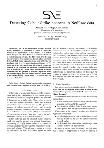
3.Compute both the horizontal and vertical hydrostatic forces acting on a1-foot wide section of the sloping rectangular gate shown below.14
4.Compute the net horizontal force acting on a 1-foot wide section of thegate separating two tanks as shown below. The specific gravity of theoil in the right-hand tank is 0.750.Water surfaceOil surface5ft IWaterOil15i 3ft
5.The quarter cylinder is 10 feet long. Calculate the horizontal andvertical components of the forces acting on the cylinder.Water surface8fti16
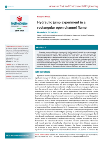
Lesson 3 - Similitude and Dimensional AnalysisSimilitudeMany approximations are made in analyzing any but the simplest of flowproblems. And for complex situations it is usually desirable to test thevalidity of the computations before large investments in hydraulic structuresare made. In many cases this validity is first checked by use of physicalmodels of proposed structures. It costs very little to build and test a modelof a structure in comparison to the cost of building a prototype, which maynot function as desired. On the other hand, analytical computations are cheapin comparison to building and testing a scale model, so models are only builtwhere the validity of the computations are in doubt.Although the basic theory for interpretation of model results is quitesimple, it is seldom possible to design and operate a flow model from theoryalone. In general, only by use of experience, judgement, and patience cancorrect prototype behavior be predicted from model results. Similarity offlows between the model and prototype requires that certain laws of similitudebe satisfied.There are many types of similarity, all of which must be obtained ifcomplete similarity is to exist between fluid phenomena. The first of theseis geometric similarity,, which states that model and prototype must have thesame shape and, therefore, that the ratios between corresponding lengths inthe model and prototype are the same. In the model and prototype of figure3-1, for example, geometric similarity exists ifLpBTIt follows that the requirements for geometric similarity are met if theratio of all linear dimensions in the model are the same as in the prototype.TbpDPrototypeJ.t bmFigure 3-1. Flow through constriction,model, and prototype.ModelCorollaries of geometric similarity are that corresponding areas varywith the squares of their linear dimensions,and that volumes vary with the cubes of their linear dimensions.17
Consider now the flows through the model and prototype, figure 3-1. Ifthe ratio of corresponding velocities and accelerations are the same throughout the flow, the two flows are said to possess kinematic similarity. Forkinematically similar flows, the streamline patterns will be similar in shape.In order to maintain geometric and kinematic similarity between the flowpictures, the forces acting on the corresponding fluid masses must be relatedby ratios similar to those above this similarity is known as dynamicsimilarity. The forces that may exist in a fluid flow are those of pressure,Fp, gravity, Fg, viscosity, F v , elasticity, FE, and surface tension, FT. Thevector sum of all forces acting on a fluid mass must equal its mass times itsacceleration, which is the inertial force, Fj. Written in mathematical termsfor the prototype(FP Fg Fv FE FT FI MI) p ,in which M mass of the fluid parcel and I acceleration of the fluidparcel. Of course an identical equation can be written for a mass of fluid inthe model. For the ratio of accelerations (and therefore velocities) to besimilar between the model and prototype requires that the ratio of inertialforces be similar, or(Fi) m Mm I m (F p F q F v F E F T ) m - - - (Fi) pMp Ip(F p F g F v F E F T ) pThe ratio of the inertial forces will be constant if the ratio of the inertialforce to each component force is constant, so dividing the inertial force byeach component force one sees that dynamic and kinematic similarity can onlybe achieved provided thatwhich states that the accelerations (Fj) due to pressure forces (Fp) must besimilar in both the mod
System of units (SI) are provided below. Abbreviations of units are defined in the conversion table below or where . is focused on open-channel hydraulics. Some concepts that are unique to open channels for exampl