Transcription
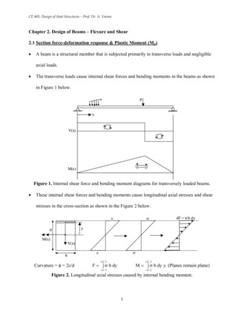
CE 405: Design of Steel Structures – Prof. Dr. A. VarmaChapter 2. Design of Beams – Flexure and Shear2.1 Section force-deformation response & Plastic Moment (Mp) A beam is a structural member that is subjected primarily to transverse loads and negligibleaxial loads. The transverse loads cause internal shear forces and bending moments in the beams as shownin Figure 1 below.wPxV(x)M(x)Figure 1. Internal shear force and bending moment diagrams for transversely loaded beams. These internal shear forces and bending moments cause longitudinal axial stresses and shearstresses in the cross-section as shown in the Figure 2 below.εσdF σ b dyydM(x)V(x)bCurvature φ 2ε/dσε d / 2 d / 2F σ b dyM σ b dy y (Planes remain plane) d / 2 d / 2Figure 2. Longitudinal axial stresses caused by internal bending moment.1
CE 405: Design of Steel Structures – Prof. Dr. A. Varma Steel material follows a typical stress-strain behavior as shown in Figure 3 below.σuσyσεyεuεFigure 3. Typical steel stress-strain behavior. If the steel stress-strain curve is approximated as a bilinear elasto-plastic curve with yieldstress equal to σy, then the section Moment - Curvature (M-φ) response for monotonicallyincreasing moment is given by Figure 4.MpCBAσySection Moment, 5εy5εyσy10εyCDECurvature, φA: Extreme fiber reaches εy B: Extreme fiber reaches 2εy C: Extreme fiber reaches 5εyD: Extreme fiber reaches 10εy E: Extreme fiber reaches infinite strainFigure 4. Section Moment - Curvature (M-φ) behavior.2
CE 405: Design of Steel Structures – Prof. Dr. A. Varma In Figure 4, My is the moment corresponding to first yield and Mp is the plastic momentcapacity of the cross-section. -The ratio of Mp to My is called as the shape factor f for the section.-For a rectangular section, f is equal to 1.5. For a wide-flange section, f is equal to 1.1.Calculation of Mp: Cross-section subjected to either σy or -σy at the plastic limit. See Figure5 below.σyPlastic centroid.A1y1A2σy A 1y2σy A 2σy(a) General cross-section(b) Stress distribution(c) Force distributionF σ y A1 σ y A 2 0 A1 A 2 A / 2A ( y1 y 2 )2Where , y1 centroid of A1 M σyy 2 centroid of A 2(d) EquationsFigure 5. Plastic centroid and Mp for general cross-section. The plastic centroid for a general cross-section corresponds to the axis about which the totalarea is equally divided, i.e., A1 A2 A/2-The plastic centroid is not the same as the elastic centroid or center of gravity (c.g.) of thecross-section.3
CE 405: Design of Steel Structures – Prof. Dr. A. Varma-As shown below, the c.g. is defined as the axis about which A1y1 A2y2.y2 A1, y1y1c.g. elastic N.A. A , y22About the c.g. A 1 y 1 A 2 y2For a cross-section with at-least one axis of symmetry, the neutral axis corresponds to thecentroidal axis in the elastic range. However, at Mp, the neutral axis will correspond tothe plastic centroidal axis. For a doubly symmetric cross-section, the elastic and the plastic centroid lie at the samepoint. Mp σy x A/2 x (y1 y2) As shown in Figure 5, y1 and y2 are the distance from the plastic centroid to the centroid ofarea A1 and A2, respectively. A/2 x (y1 y2) is called Z, the plastic section modulus of the cross-section. Values for Z aretabulated for various cross-sections in the properties section of the LRFD manual. φ Mp 0.90 Z Fy- See Spec. F1.1where,Mp plastic moment, which must be 1.5 My for homogenous cross-sectionsMy moment corresponding to onset of yielding at the extreme fiber from an elastic stressdistribution Fy S for homogenous cross-sections and Fyf S for hybrid sections.Z plastic section modulus from the Properties section of the AISC manual.S elastic section modulus, also from the Properties section of the AISC manual.4
CE 405: Design of Steel Structures – Prof. Dr. A. VarmaExample 2.1 Determine the elastic section modulus, S, plastic section modulus, Z, yieldmoment, My, and the plastic moment Mp, of the cross-section shown below. What is the designmoment for the beam cross-section. Assume 50 ksi steel.12 in.F10.75 in.16 in.W t 0.5 in.wF21.0 in.15 in. Ag 12 x 0.75 (16 - 0.75 - 1.0) x 0.5 15 x 1.0 31.125 in2Af1 12 x 0.75 9 in2Af2 15 x 1.0 15.0 in2Aw 0.5 x (16 - 0.75 - 1.0) 7.125 in2 distance of elastic centroid from bottom y9 (16 0.75 / 2) 7.125 8.125 15 0.5 6.619 in.31.125Ix 12 0.753/12 9.0 9.0062 0.5 14.253/12 7.125 1.5062 15.0 13/12 y 15 6.1192 1430 in4Sx Ix / (16-6.619) 152.43 in3My-x Fy Sx 7621.8 kip-in. 635.15 kip-ft. distance of plastic centroid from bottom y p 15.0 1.0 0.5 ( y p 1.0) 31.125 15.56252 y p 2.125 in.5
CE 405: Design of Steel Structures – Prof. Dr. A. Varmay1 centroid of top half-area about plastic centroid y2 centroid of bottom half-area about plas. cent. 9 13.5 6.5625 6.5625 10.5746 in.15.56250.5625 0.5625 15.0 1.625 1.5866 in.15.5625Zx A/2 x (y1 y2) 15.5625 x (10.5746 1.5866) 189.26 in3Mp-x Zx Fy 189.26 x 50 9462.93 kip-in. 788.58 kip-ft. Design strength according to AISC Spec. F1.1 φbMp 0.9 x 788.58 709.72 kip-ft. Check Mp 1.5 MyTherefore, 788.58 kip-ft. 1.5 x 635.15 949.725 kip-ft. Reading Assignment6- OK!
CE 405: Design of Steel Structures – Prof. Dr. A. Varma2.2 Flexural Deflection of Beams – ServiceabilitySteel beams are designed for the factored design loads. The moment capacity, i.e., thefactored moment strength (φbMn) should be greater than the moment (Mu) caused by thefactored loads.A serviceable structure is one that performs satisfactorily, not causing discomfort orperceptions of unsafety for the occupants or users of the structure.-For a beam, being serviceable usually means that the deformations, primarily the verticalslag, or deflection, must be limited.-The maximum deflection of the designed beam is checked at the service-level loads. Thedeflection due to service-level loads must be less than the specified values.The AISC Specification gives little guidance other than a statement in Chapter L,“Serviceability Design Considerations,” that deflections should be checked. Appropriatelimits for deflection can be found from the governing building code for the region.The following values of deflection are typical maximum allowable total (service dead loadplus service live load) deflections. Plastered floor construction – L/360 Unplastered floor construction – L/240 Unplastered roof construction – L/180 In the following examples, we will assume that local buckling and lateral-torsional bucklingare not controlling limit states, i.e, the beam section is compact and laterally supported alongthe length.7
CE 405: Design of Steel Structures – Prof. Dr. A. VarmaExample 2.2 Design a simply supported beam subjected to uniformly distributed deadload of 450 lbs/ft. and a uniformly distributed live load of 550 lbs/ft. The dead load doesnot include the self-weight of the beam. Step I. Calculate the factored design loads (without self-weight).wU 1.2 wD 1.6 wL 1.42 kips / ft.MU wu L2 / 8 1.42 x 302 / 8 159.75 kip-ft.Step II. Select the lightest section from the AISC Manual design tables.From pageof the AISC manual, select W16 x 26 made from 50 ksi steel withφbMp 166.0 kip-ft.Step III. Add self-weight of designed section and check designwsw 26 lbs/ftTherefore, wD 476 lbs/ft 0.476 lbs/ft.wu 1.2 x 0.476 1.6 x 0.55 1.4512 kips/ft.Therefore, Mu 1.4512 x 302 / 8 163.26 kip-ft. φbMp of W16 x 26.OK!Step IV. Check deflection at service loads.w 0.45 0.026 0.55 kips/ft. 1.026 kips/ft. 5 w L4 / (384 E Ix) 5 x (1.026/12) x (30 x 12)4 / (384 x 29000 x 301) 2.142 in. L/360- for plastered floor constructionStep V. Redesign with service-load deflection as design criteriaL /360 1.0 in. 5 w L4/(384 E Ix)Therefore, Ix 644.8 in48
CE 405: Design of Steel Structures – Prof. Dr. A. VarmaSelect the section from the moment of inertia selection tables in the AISC manual. See page– select W21 x 44.W21 x 44 with Ix 843 in4 and φbMp 358 kip-ft. (50 ksi steel).Deflection at service load 0.765 in. L/360- OK!Note that the serviceability design criteria controlled the design and the sectionExample 2.3 Design the beam shown below. The unfactored dead and live loads are shown inthe Figure.10 kips (live load)0.67 k/ft. (dead load)0.75 k/ft. (live load)15 ft.30 ft. Step I. Calculate the factored design loads (without self-weight).wu 1.2 wD 1.6 wL 1.2 x 0.67 1.6 x 0.75 2.004 kips / ft.Pu 1.2 PD 1.6 PL 1.2 x 0 1.6 x 10 16.0 kipsMu wU L2 / 8 PU L / 4 225.45 120 345.45 kip-ft.Step II. Select the lightest section from the AISC Manual design tables.From page of the AISC manual, select W21 x 44 made from 50 ksi steel withφbMp 358.0 kip-ft.Self-weight wsw 44 lb/ft.9
CE 405: Design of Steel Structures – Prof. Dr. A. Varma Step III. Add self-weight of designed section and check designwD 0.67 0.044 0.714 kips/ftwu 1.2 x 0.714 1.6 x 0.75 2.0568 kips/ft.Therefore, Mu 2.0568 x 302 / 8 120 351.39 kip-ft. φbMp of W21 x 44.OK!Step IV. Check deflection at service loads.Service loads Distributed load w 0.714 0.75 1.464 kips/ft. Concentrated load P D L 0 10 kips 10 kipsDeflection due to uniform distributed load d 5 w L4 / (384 EI)Deflection due to concentrated load c P L3 / (48 EI)Therefore, service-load deflection d c 5 x 1.464 x 3604 / (384 x 29000 x 12 x 843) 10 x 3603 / (48 x 29000 x 843) 1.0914 0.3976 1.49 in.Assuming unplastered floor construction, max L/240 360/240 1.5 in.Therefore, max- OK!10
CE 405: Design of Steel Structures – Prof. Dr. A. Varma2.3 Local buckling of beam section – Compact and Non-compact Mp, the plastic moment capacity for the steel shape, is calculated by assuming a plastic stressdistribution ( or - σy) over the cross-section. The development of a plastic stress distribution over the cross-section can be hindered by twodifferent length effects:(1) Local buckling of the individual plates (flanges and webs) of the cross-section beforethey develop the compressive yield stress σy.(2) Lateral-torsional buckling of the unsupported length of the beam / member beforethe cross-section develops the plastic moment Mp.MMFigure 7. Local buckling of flange due to compressive stress (σ) The analytical equations for local buckling of steel plates with various edge conditions andthe results from experimental investigations have been used to develop limiting slendernessratios for the individual plate elements of the cross-sections. See Spec. B5 (page 16.1 – 12), Table B5.1 (16.1-13) and Page 16.1-183 of the AISC-manual Steel sections are classified as compact, non-compact, or slender depending upon theslenderness (λ) ratio of the individual plates of the cross-section.11
CE 405: Design of Steel Structures – Prof. Dr. A. Varma -Compact section if all elements of cross-section have λ λp-Non-compact sections if any one element of the cross-section has λp λ λr-Slender section if any element of the cross-section has λr λIt is important to note that:-If λ λp, then the individual plate element can develop and sustain σy for large values ofε before local buckling occurs.-If λp λ λr, then the individual plate element can develop σy but cannot sustain itbefore local buckling occurs.If λr λ, then elastic local buckling of the individual plate element occurs.Co mpressive axial stress, σ-CompactσyNon-CompactSlenderEffective axial strain, εFigure 8. Stress-strain response of plates subjected to axial compression and local buckling. Thus, slender sections cannot develop Mp due to elastic local buckling. Non-compactsections can develop My but not Mp before local buckling occurs. Only compact sections candevelop the plastic moment Mp. All rolled wide-flange shapes are compact with the following exceptions, which are noncompact.12
CE 405: Design of Steel Structures – Prof. Dr. A. Varma- W40x174, W14x99, W14x90, W12x65, W10x12, W8x10, W6x15 (made from A992)The definition of λ and the values for λp and λr for the individual elements of various crosssections are given in Table B5.1 and shown graphically on page 16.1-183. For example,SectionWide-flangeChannelSquare or Rect.BoxPlate elementλλpλrFlangebf/2tf0.38E / Fy0.38E / FLWebh/tw3.76E / Fy5.70E / FyFlangebf/tf0.38E / Fy0.38E / FLWebh/tw3.76E / Fy5.70E / FyFlange(b-3t)/t1.12E / Fy1.40E / FyWeb(b-3t)/t3.76E / Fy5.70E / FyIn CE405 we will design all beam sections to be compact from a local buckling standpoint13
CE 405: Design of Steel Structures – Prof. Dr. A. Varma2.4 Lateral-Torsional Buckling The laterally unsupported length of a beam-member can undergo lateral-torsional bucklingdue to the applied flexural loading (bending moment).(a)M(b)MMMFigure 9. Lateral-torsional buckling of a wide-flange beam subjected to constant moment.14
CE 405: Design of Steel Structures – Prof. Dr. A. Varma Lateral-torsional buckling is fundamentally similar to the flexural buckling or flexuraltorsional buckling of a column subjected to axial loading.-The similarity is that it is also a bifurcation-buckling type phenomenon.-The differences are that lateral-torsional buckling is caused by flexural loading (M), andthe buckling deformations are coupled in the lateral and torsional directions. There is one very important difference. For a column, the axial load causing bucklingremains constant along the length. But, for a beam, usually the lateral-torsional bucklingcausing bending moment M(x) varies along the unbraced length.-The worst situation is for beams subjected to uniform bending moment along theunbraced length. Why?2.4.1 Lateral-torsional buckling – Uniform bending moment Consider a beam that is simply-supported at the ends and subjected to four-point loading asshown below. The beam center-span is subjected to uniform bending moment M. Assumethat lateral supports are provided at the load points.PPLb Laterally unsupported length Lb. If the laterally unbraced length Lb is less than or equal to a plastic length Lp then lateraltorsional buckling is not a problem and the beam will develop its plastic strength Mp. Lp 1.76 ry xE / Fy- for I members & channels (See Pg. 16.1-33)15
CE 405: Design of Steel Structures – Prof. Dr. A. Varma If Lb is greater than Lp then lateral torsional buckling will occur and the moment capacity ofthe beam will be reduced below the plastic strength Mp as shown in Figure 10 below.Mn MpZx Fy Mp Lb L p M n M p ( M p M r ) L L rp Sx (Fy – 10) MrMoment Capacity, M nMn Lpπ 2 EI y L2b GJ π 2 ECw L2bLrUnbraced length, LbFigure 10. Moment capacity (Mn) versus unsupported length (Lb). As shown in Figure 10 above, the lateral-torsional buckling moment (Mn Mcr) is a functionof the laterally unbraced length Lb and can be calculated using the equation:πMn Mcr Lbwhere,2 π E I y C wE I y G J L b Mn moment capacityLb laterally unsupported length.Mcr critical lateral-torsional buckling moment.E 29000 ksi;G 11,200 ksiIy moment of inertia about minor or y-axis (in4)J torsional constant (in4) from the AISC manual pages .Cw warping constant (in6) from the AISC manual pages .16
CE 405: Design of Steel Structures – Prof. Dr. A. Varma This equation is valid for ELASTIC lateral torsional buckling only (like the Euler equation).That is it will work only as long as the cross-section is elastic and no portion of the crosssection has yielded. As soon as any portion of the cross-section reaches the yield stress Fy, the elastic lateraltorsional buckling equation cannot be used.-Lr is the unbraced length that corresponds to a lateral-torsional buckling momentMr Sx (Fy –10).- Mr will cause yielding of the cross-section due to residual stresses.When the unbraced length is less than Lr, then the elastic lateral torsional buckling equationcannot be used. When the unbraced length (Lb) is less than Lr but more than the plastic length Lp, then thelateral-torsional buckling Mn is given by the equation below: Lb L p then M n M p ( M p M r ) L L rp -If Lp Lb Lr,-This is linear interpolation between (Lp, Mp) and (Lr, Mr)-See Figure 10 again.17
CE 405: Design of Steel Structures – Prof. Dr. A. Varma2.4.2 Moment Capacity of beams subjected to non-uniform bending moments As mentioned previously, the case with uniform bending moment is worst for lateraltorsional buckling. For cases with non-uniform bending moment, the lateral torsional buckling moment isgreater than that for the case with uniform moment. The AISC specification says that:-The lateral torsional buckling moment for non-uniform bending moment case Cb x lateral torsional buckling moment for uniform moment case. Cb is always greater than 1.0 for non-uniform bending moment.-Cb is equal to 1.0 for uniform bending moment.-Sometimes, if you cannot calculate or figure out Cb, then it can be conservativelyassumed as 1.0. Cb 2.5 M max12.5 M max 3 MA 4 MB 3 Mcwhere, Mmax magnitude of maximum bending moment in LbMA magnitude of bending moment at quarter point of LbMB magnitude of bending moment at half point of LbMC magnitude of bending moment at three-quarter point of Lb The moment capacity Mn for the case of non-uniform bending moment-Mn Cb x {Mn for the case of uniform bending moment} Mp-Important to note that the increased moment capacity for the non-uniform moment casecannot possibly be more than Mp.-Therefore, if the calculated values is greater than Mp, then you have to reduce it to Mp18
CE 405: Design of Steel Structures – Prof. Dr. A. VarmaMoment Capacity, MnMpMrCb 1.5Cb 1.2Cb 1.0LpLrUnbraced length, LbFigure 11. Moment capacity versus Lb for non-uniform moment case.2.5 Beam DesignExample 2.4Design the beam shown below. The unfactored uniformly distributed live load is equal to 3kips/ft. There is no dead load. Lateral support is provided at the end reactions.wL 3 kips/ft.24 ft.Lateral support / bracingStep I. Calculate the factored loads assuming a reasonable self-weight.Assume self-weight wsw 100 lbs/ft.Dead load wD 0 0.1 0.1 kips/ft.Live load wL 3.0 kips/ft.Ultimate load wu 1.2 wD 1.6 wL 4.92 kips/ft.Factored ultimate moment Mu wu L2/8 354.24 kip-ft.19
CE 405: Design of Steel Structures – Prof. Dr. A. VarmaStep II. Determine unsupported length Lb and CbThere is only one unsupported span with Lb 24 ft.Cb 1.14 for the parabolic bending moment diagram, See values of Cb shown in Figure.Step III. Select a wide-flange shapeThe moment capacity of the selected section φbMn Mu(Note φb 0.9)φbMn moment capacity Cb x (φbMn for the case with uniform moment) φbMp-Pages in the AISC-LRFD manual, show the plots of φbMn-Lb forthe case of uniform bending moment (Cb 1.0)-Therefore, in order to select a section, calculate Mu/Cb and use it with Lb to find the firstsection with a solid line as shown in class.-Mu/Cb 354.24/1.14 310.74 kip-ft.-Select W16 x 67 (50 ksi steel) with φbMn 357 kip-ft. for Lb 24 ft. and Cb 1.0-For the case with Cb 1.14,φbMn 1.14 x 357 406.7 kip-ft., which must be φbMp 491 kip-ft.OK! Thus, W16 x 67 made from 50 ksi steel with moment capacity equal to 406.7 kip-ft. for anunsupported length of 24 ft. is the designed section.Step IV. Check for local buckling.λ bf / 2tf 7.7; Corresponding λp 0.38 (E/Fy)0.5 9.192Therefore, λ λp- compact flangeλ h/tw 34.4; Corresponding λp 3.76 (E/Fy)0.5 90.5Therefore, λ λp- compact webCompact section. - OK!This example demonstrates the method for designing beams and accounting for Cb 1.020
CE 405: Design of Steel Structures – Prof. Dr. A. VarmaExample 2.5Design the beam shown below. The concentrated live loads acting on the beam are shown in theFigure. The beam is laterally supported at the load and reaction points.30 kips30 kipswsw 0.1 kips/ft.12 ft.8 ft.10 ft.30 ft.Lateral support / bracingStep I. Assume a self-weight and determine the factored design loadsLet, wsw 100 lbs/ft. 0.1 kips/ft.PL 30 kipsPu 1.6 PL 48 kipswu 1.2 x wsw 0.12 kips/ft.The reactions and bending moment diagram for the beam are shown below.48 kips48 kipswsw 0.12 kips/ft.ADB12 ft.C8 ft.10 ft.46.6 kipsA53 kipsBC524 kip-ft.550.6 kip-ft.Step II. Determine Lb, Cb, Mu, and Mu/Cb for all spans.21D
CE 405: Design of Steel Structures – Prof. Dr. A. 3.8It is important to note that it is possible to have different Lb and Cb values for differentlaterally unsupported spans of the same beam.Step III. Design the beam and check all laterally unsupported spansAssume that span BC is the controlling span because it has the largest Mu/Cb although thecorresponding Lb is the smallest.From the AISC-LRFD manual select W21 x 68 made from 50 ksi steel (page )Check the selected section for spans AB, BC, and CDSpanLb(ft.)AB12BC8CD10φ bM nfor Cb 1.0from5071.67φ bM nfor Cb valuecol. 3 x col. 4846.75721.0572.05401.67901.8CbThus, for span AB, φbMn 600 kip-ft. Mu- OK!for span BC, φbMn 572.0 kip-ft. Mu-OK!For span CD, φbMn 600 kip-ft. Mu-OK!22φ bM plimit600 kip-ft600 kip-ft.
CE 405: Design of Steel Structures – Prof. Dr. A. VarmaStep IV. Check for local bucklingλ bf / 2tf 6.0; Corresponding λp 0.38 (E/Fy)0.5 9.192Therefore, λ λp- compact flangeλ h/tw 43.6; Corresponding λp 3.76 (E/Fy)0.5 90.55Therefore, λ λp- compact webCompact section.- OK!This example demonstrates the method for designing beams with several laterally unsupportedspans with different Lb and Cb values.Example 2.6Design the simply-supported beam shown below. The uniformly distributed dead load is equal to1 kips/ft. and the uniformly distributed live load is equal to 2 kips/ft. A concentrated live loadequal to 10 kips acts at the mid-span. Lateral supports are provided at the end reactions and atthe mid-span.10 kipswD 1.0 kips/ft.wL 2.0 kips/ft.ACB12 ft.12 ft.Step I. Assume the self-weight and calculate the factored design loads.Let, wsw 100 lbs/ft. 0.1 kips/ft.wD 1 0.1 1.1 kips/ft.wL 2.0 kips/ft.wu 1.2 wD 1.6 wL 4.52 kips/ft.Pu 1.6 x 10 16.0 kips23
CE 405: Design of Steel Structures – Prof. Dr. A. VarmaThe reactions and the bending moment diagram for the factored loads are shown below.16 kipswu 4.52 kips/ft.B12 ft.12 ft.62.24 kipsx62.24 kipsM(x) 62.24 x - 4.52 x2 /2Step II. Calculate Lb and Cb for the laterally unsupported spans.Since this is a symmetric problem, need to consider only span ABLb 12 ft.; C b 12.5 M max2.5 M max 3 M A 4 M B 3 M cM(x) 62.24 x – 4.52 x2/2Therefore,MA M(x 3 ft.) 166.38 kip-ft.- quarter-point along Lb 12 ft.MB M(x 6 ft.) 292.08 kip-ft.- half-point along Lb 12 ft.MC M(x 9ft.) 377.1 kip-ft-three-quarter point along Lb 12 ft.Mmax M(x 12 ft.) 421.44 kip-ft.- maximum moment along Lb 12ft.Therefore, Cb 1.37Step III. Design the beam sectionMu Mmax 421.44 kip-ft.Lb 12.0 ft.; Cb 1.37Mu/Cb 421.44/1.37 307.62 kip-ft.-Select W21 x 48 made from 50 ksi with φbMn 322 kip-ft. for Lb 12.0 ft. and Cb 1.0-For Cb 1.37, φbMn 441.44 k-ft., but must be or φbMp 398 k-ft.24
CE 405: Design of Steel Structures – Prof. Dr. A. Varma-Therefore, for Cb 1.37, φbMn 398 k-ft. MuStep IV. Redesign the section-Select the next section with greater capacity than W21 x 48-Select W18 x 55 with φbMn 345 k-ft. for Lb 12 ft. and Cb 1.0For Cb 1.37, φbMn 345 x 1.37 472.65 k-ft. but must be φbMp 420 k-ft.Therefore, for Cb 1.37, φbMn 420 k-ft., which is Mu (421.44 k-ft), (NOT OK!)-Select W 21 x 55 with φbMn 388 k-ft. for Lb 12 ft. and Cb 1.0For Cb 1.37, φbMn 388 x 1.37 531.56 k-ft., but must be φbMp 473 k-ft.Therefore, for Cb 1.37, φbMn 473 k-ft, which is Mu (421.44 k-ft). (OK!)Step V. Check for local buckling.λ bf / 2tf 7.87; Corresponding λp 0.38 (E/Fy)0.5 9.192Therefore, λ λp- compact flangeλ h/tw 50.0; Corresponding λp 3.76 (E/Fy)0.5 90.55Therefore, λ λp- compact webCompact section.- OK!This example demonstrates the calculation of Cb and the iterative design method.25
CE 405: Design of Steel Structures – Prof. Dr. A. Varma Chapter 2. Design of Beams – Flexure and Shear 2.1 Section force-deformation response & Plastic Moment (Mp) A beam is a structural member that