Transcription
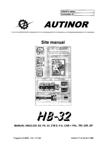
CHent's name :Controller N" :AUTINORSite manual00-;-:.:::::,: :;::::::':'".',.::I ':: ',: J ', ; " 0:', .,.,. .'1-18-32MANUAL H832-230. 84. P6. 3V. Z M S. P.A. CAB PAL. TRI. DIR. SPProgramm B-HB32 - V15 7/11/95Edition n01 du 30 avril 1996
WARNINGThis manual is deemed correct on going 10 press. Il is Iinked 10 the program version shawn on thefront page, however this version may evolve wilhout influencing the contents of this manuel, whichmay in itself be changed wtthout prier waming.The information contained has been scrupulously cnecked. Howvever AUTINOR declines ailresponsibility for error or omission.Should yeu notice any discrepancy or unclear description, or if yeu nave any suggestions. we wouldappreciate YOUf wrilten comments (by mail or fax) to :Société AUTINORZ.A. Les Marlières59710 AVELIN!if[331 03-20-62-56-00.!S [33103-20-62-56-41This manual rs the property of AUTINOR, trom whom it may be bought (al the above address). Il mayhOwever by freely cooreo in oroer to communtcate information to those who might need il.We can only authorize a complete copy, without addition nor removal of infonnationWhere quotations are taken. the fo\\owing at least must be noted :the company name of AUTINOR,the program version to which it refers,the number and date of the original edition.ELECTROMAGNETIC COMPATIBILITYSince the tst January 1996 ail lift installations are obliged to respect the essential requirements of theEuropean Directive 89/336/CEE conceming Electromagnetic Compatibility (EMC).The HB-32 equlpment is only one compone nt of an installation; il îs therefore nol obliged 10 show the(E marking as stated in this directive. However in oroer 10 alfow you 10 write your declaration ofconfonnitv, and according to professional rules. ail AUTINOR controllers are supplied wilh anengagement of conformity.Your declaration of conrormny can only rest on this engagement.if the HB-3Z equipment has been Installed exactly as advised in this manual. Copyright 1998 AUTINOR Ali righls reservee.
HB32page 5Site manualCONTENTS1) How to install the controller cabinet,72) Minimum connections neceasary for initial movernentPower-np10.123) Controller parameter/diagnostic communication deviee134) Safety lane wiring195) Machine room wiring6) Landing wiring,20. 217) Car wiring228) Direct three phases door operator, front and rear doors239) Wiring checks2410) Setting-up the slotted tape and brackets2511) Settinq-up the magnets for the door-zone read by proximity switches2612) Automatic set-up of levels2713) What to know before starting off at full speed3014) Parameters adjustment at full speed31-To modify the slow down distance31-Automatic adjustment of the up stopping precision31 Automatic adjustment of the down stopping precision32-Automatic adjustment of the hysterisis zone32-Positioning the EM magnets3215) Parameters to be adjusted on site3416) Parameters table-Controller parameters35-Parameters concemed the slotted tape3817) Inputs 1 outputs table-Control1er Inputs 1 outputs3918) Fault codes list4119) Location of terminal blacks and function of fuses4420) Electric diagrams4621) Additional items48-Indicators.-Non standard wiring CH.S).-Further evolutions and improvements.
Site manualHB32page 71) INFORMATIONS NECESSARYFOR HANDLING AUTINOR EQUIPMENTAND HOW TO INSTALL THE CONTROLLER CABINET (1/2) Equipment weight : approximately 40 Kg. Handling advice for AUTINOR equipment.lIVhafever the Joad, handling operations can be dangerous (collision, dropping, crushing, . .). VVheneverpossible use mechanical handling rather than manual handling. When manuaf handling can not be avoided, respectthe rutes.european tevet, these nües -are set ouf in the Directive 901269/CEE, Consi! Directive dated 19 May 1990« conceming minima! heath and s8fefy instructions for manuaJ tosa handling with risks, to the worker, notably in theAtlower spiral areaJ).
HB32page 9Site manualHOW TO INSTALL THE CONTROLLER CABINET (2/2) n 57'15uppor bar(fixed by 2 06x38 screws plugs supply in aplastic oag in a cover).iPlasticbagfar fixingcabinet. Base-'--C;b"inelO.25m1Controller dimensions: L 560 mm, H 1000 mm, P 250 mmProtection against electrical shocks : IP 20Don't forget than the EN-81·2 part 1 Standard § 6.3.2.1 (a), amended byBritish national variation B5 5655 § V.3.14 requires that :6.3.2.1 The dimension of machine room shaH be sufficient to permit easy and sale access for servicingpersonnel to ail components, especially the electn'cal equipment.ln parficular there shaH be provided :(a) a c/ear hon"zontal area in front of the panels and the cabinet. This area is defined as tol/ows : (N.c)depth, measured trom extemaf surteoe of the enclosures, al least 0.9 m. This distance may be reduced to0.6 m in front of profruding çontrols (handles, etc.).widlh, the full width of panel or cabinets by 2. 14 m high.
page 10Site manualHB322) MINIMUM CONNECTIONS NECESSARY FOR INITIALMOVEMENT (1/3)'3'CHECK THAT THE MACHINE\:!,) RDDM INSPECTION OPTION15 PROGRAMMED "OPTMAN"MUST BE PROGRAMMED - ON At addres 07 - segment 4CD 0leJ-RJr l TH lïML1Il l'v I S '2'.\V@MG ,W. ".OOOOUuKM11KM17 "BG15GDOV b;H: KM12KC23 N705TATE OF THE5AFETY LANE.tW 6 810 ,, OV]0CS1 §';01 t·1 KA16 (BG19) :ovJ -"" THE 3 LEDs (6, 8 & 10)NEED TO BE LIT UPBEFORE THE LIFTWILLMOVEELECTROMECHANICALTERMINAL RAIL.Figure 1 Minimum connection uccessaryrOTinitial movemcnt - hydraulic with sloUed tape
HB31Site manualDuring thepage 11MINIMUM CONNECTIONS NECESSARYFOR INITIAL MOVEMENT (2/3)construction phase, you can temporarily use the av, GM and GD inputs on theKM12connector for running up and down respectively.CHECK THAT THE MACHINE ROOM INSPECTION OPTION IS PROGRAMMED - "OPTMAN"MUST BE PROGRAMMED ON AT ADDRESS 07 - SEGMENT 4CONNECT AS FOLLOWS :(see figure 1 opposite for where to make these connection)Connect the thermistor and/or the .purnp motor safety thermo-contact betwee:]the STH and av terminais on the KM11 connector. ---Temporarily bridge OVand INS on the KC23 connectorThe "up'' and "down" push buttons on the inspection box on the car roof ta theGM, GD and av terminais on the KM12 connecter.The safety circuits 1S, 6, 8 and 1a on the electromechanical terminal railThe pump motor ta U1, V1, W1 and U2, V2, W2 on the electromechanicalteminal rail, and Ealth ta the ealth col/ecting bar. The electrovalves ta the KH1 connector on the BG16; note that certain(j)The power supply ta L 1, L2, L3 and Neutral if available, Ealth ta the ealthcol/ecting bar. Temporarily bridge CS1 and av on KA13 and possibly CS2 and av on KA16 ofthe BG19 board (when there are 2 door operators).hydraulic power units rsquire connections to the electromechanica! terminal rail.When there is a mechanical anti-creep temporarily bridge the anti-creep inputs,av, TAQ1, and TAQ2 on KC31 connector of the BG16 board. If there is onlyone antJ-creep, bridge between the TAQ1 and TAQ2 inputs.Note that if you are using anti-creeps, the antt-creep (TAQUET) option (address SCsegment 0) should be ON.The ail thermostat, if there is one, between MTH and av on KM17, if nottemporarily bridge MTH and OV.
HB32Site manualPOWER-UP FOR INITIAL MOVEMENT (3/3)page 12
HB32page 13Site manual3) PARAMETER 1 DIAGNOSTIC COMMUNICATION DEVICE.i /!tADrtPARBG17MODIFParameter --t--modeindicatorECRITFigure 2 Position of the sliding swltches for parameter mode -- --fFigure 3 Pesltion of the communication devieeBG15
HB32Site manualpage 14THE PARAMETERS AND THEIR MYSTERIESThis chapter contains information which will allow you to adapt the HB-32equipment to the specifie conditions of the lift on which it is installed.This adaptation ls controlled by parame/ers, which you can modify according to yourneeds using the removable parameter 1 dlaqnostic! communication device asdescribed below in the paragraph Accessing the parameters.The parameters are memorized in a particular type of rnernory called an EEPROM 2(or E2PROM) which keeps the infonnation even wh en the equipment is switchedoff.Each parameter is linled to an abridged name and an address which correspondsto the position at which it is memorizedin the EEPROM chip. As computers arestrange creatures, the addresses are expressed in a particular numbering systme,called an hexadecimal system ( a numbering system in base 16), which is made upof numbers (from 0 to 9) as weil as letters (A to F). This peculiarity aside, you onlyneed to consider the address as an marker (think of the game of battleships).Accessing the parametersAs mentionned above, you can ses and modify the parameters using theparameter/diagnostic communication tool; this consists of a BG17 circuit boardwhich is plugged into the BG15 (figure 3, page 13).The BG17 board is made up of 2 displays with 7 segments, 2 push buttons and 2sliding switches (figure 2, page 13).Tc access the parameters, the left-hand sliding switch must be atthe bottom; thisposition is shown as PAR (as in PARAMETER) on the board.When the sliding switch is in this position, the decimal point on the right-handdisplay lights up to remind you that you are looking at or modifying the parameters.1Nole for those used to using our previos manuals :The term "parameter/diagnostic communication deviee replaces the old term "communicaUontool" to avold any risk of confusion with the equipment used ta communicate (directly or bytelephone link) wilh the computer system (lelesurveillance and/or telediagnostic).2EEPROM stands for Electrically Erasable Programab/e ReadOnly Memory.
HB32page 15Site manualDISPLAY MODESDepending on the information ta be displayed, the HB-32 uses the most appropriatemethod of showing the information.Digit ModeThe digit mode is useful ta read or programme times, or the number of floors, or thenumber of doors for example.Example : If we have 2 door operators, we pragram 02 at address 03.:-::,-:·"'Q'FI1 t ·l'EJT:. . '"''.,::::::.:::Segment Mode, - - --- -- . .: ."" " . " " , , .The segment mode uses the individu al vertical segments on the display as shawnbelow.Segment 3Segment 2rr11 Segment 0 Segment 1This mode is useful ta activate or deactivate different functions :Example: Ta activate the "flashing direction arrows" option, segment5 at address 08 must be ON.The segment mode is also useful ta view the state of inputs and outputs:Example : Ta check that the CO input (car cali ta level 0) is correctlyread by the HB-32, you need ta look at segment 0 ataddress 00.Ta change fram digit ta segment mode and vice-versa, slide the ADR-DON MODIF switch ta ADRIDON and press bath buttons at the same time, and release.
HB32page 16Site manualTa change the address or ta view the inputs, outputs and parametersoADRIDONt1 G)Check that the ADRIDON-MODIF switch is on ADRIDON./l'IOOIFScroll ta the desired address (eg 03) by pressing the push bullons below thedisplay.Press either butten and the address will be displayed. Each time you press abutton the value displayed will be increased by 1. " [1 11''''' ,7 Press the right hand button10 times ta change-----, ':;'-:')MODlf[QIBG17êi'k. ';'1fu1from address 09 taaddress 03::::. ' L- ECRITLeave the buttons for 1 second, and the contents of the selected address will bedisplayed indefinitely.IlIilJi; "T,1]- [QI,BG17'ECRIT' ---r RAM1 [@l[] 1MDOIF ADRIOON1 second \ater .'--- MDDII'BG17Il Il]-'1.:.:: -ECRIT -: .JTa remind yourself of the current addressIf you forget the address you are at,oADRIOO Siide the ADRIDON-MODIF switch ta MODIF.1, AOR/DONThen slide it back ta ADRIDON. This will show you theaddress for 1 second, and then the contents.(!)t10
page 17Site manualHB32Ta CHANGE THE PARAMETERSCheck that the RAM-PAR switch is ta PAR.Al ln digit modeoGo ta the parameter address as explained on the page belore (eg 03).i [Q]G(iMO IF1PARMODIF1tJ] L-- BDBG171 second later .rrFnLBG17ECRIT'III] , ECRIT6Siide the ADRIDON-MODIF switch ta MODIF.8Use the push buttons ta increase/decrease ta the new value (eg 02).i [QIOJAI'PARBG17[IleCRITMOIlIF···L-- 11!i]ffijjj]Push once on the right hand buttanta change the value Iram01 ta 02.MDDIFeA'BG17 . eCRIT1.'lA" {H···; ."""1 ' "[Q].MOOIFBG17Register the new value by pushing and releasingbath buttons at the same time.oSiide the ADRIDON-MODIF switch back ta ADRIDON.Address 03 will show lallawed by its value 02.
HB32page 18Site manualB) ln segment modeoGo ta the parameter address as previously explained (eg 08).If the contents are displayed as a figure (82 in the example below), check thatthe right hand switch is in the upper position, and press bath buttons at theseme lime; this will pass you into segment mode. The current address will bedisplayed followed by the contents shawn in segments. If not pass ontostage @.1"PAI'l 1l2J AOf DtMDalF""BG17MDDIF L-- Press1 BG17- CECRITand release .0 The left-hand button acts on the TOP ROWof segments (4 ta 7), The right-hand button acts on the BOTTOMROW of segments (0 ta 3).6Siide the ADRIDON-MODIF switch ta MODIF.ADR/ODN Mt ln our example we want to activate the "flashing directionarrow" function (address 08 segment 5).We have ta Iight up segment 5 while keeping on ail othersegments in their present staten.&hlng dl«JclJan a"ownashlng direction alfOWnashln dl .etIon 8m:lWRAM""BG17MDDIFPressPressonceonce lADRlDDN1 t@ 1MDDIF Repeat stageOandOpresented at theprevious page.
page 19Site manualHB324) CONNECTING THE SAFETY LANE""( ) ELECTRO\IAlVEPOWERSUPPlYe·250V",'" I"l 1'"0 Maxi"""" L r-t- --,y"PUMPMOTORCONTAcrORS1"""'CA "POWER SUPPlY8PROTECTION(§ 14.1.1.3)SAFETY LANE" Nij,§Z g ln1----- -----11ELECTRo-C: g;; R51 1 TOP OVER1870TRAVEL lIMIT o···(§ 10.5.3.1)DISSIPATION708UFFER o. .(§ 10.4.3.3)TRANSMISSION Of Tl1ECM POSITIONTO Tl1EflNPJ.lIMIT SWITCH(§ 10,5.22b)TRANSMISSION OF THERAM POSITIONTO THEFINAL L1MIT SWITCH(§ 10.5.2-3.b)O\IERSPËEO700-'"0-··7 00-··7 0OVERSf'EEOGOVERNORRELEASE0--·7 0(§s. 10.210,2)265."fRVliil'i,I! 1SAmyGEARSWITCH(§ 9.8.8)SCAC'""CE(§ 10.6)(CEN 182)EMERGENCY STOPDN CAR ROOf 0-"(§8.1S.bjn- (§8,125,2)CM STOP BUTTON(§14.2-2-2)RETURNTOEXTENDEDPOSITIONOf ANTI-CREEP 8UfFER(§ 9. 11.10)0-"ooooSliAfT EMERGENCY"" 0·70(§ 5.2.2-2-2)pjT BOTTOMSWlTCH J- .{§5.7.25}GOVERNOR RETURNPULLEYSW1TCH(§ 9.10.210.3)0-'"RElATMCABLE - EXTENSION{§B.33}(CEN 70)(§10.5) o .(CEN 237) -- 8CAR GA'"8 o- e'oLANDINGCONTACTtocss(§ 8,8.2)(§ 7,7-1'.2), (§ U,4)(§ 5.4.3.22)(§7.7.3.1)PULLEY'0oo RN""''' ioSLACK CABLE-o0-·.;0CARSA '''''TRAP SWITCHG S (§9.10.210.1)IC 0-··70(§G.4.5).- -Ro lOoDolo11DID1/ ;ou.od
Site manualHB32page 205) MACHINE ROOM WIRINGV,VMLEAEV'GMV MARTINI3VMaRisOMAR v.V3VMDEBEVDUsedVMPEYIDEVS0Not used,VDC supply "Diode Ji Input voltage220 or :3BOVVAC supply '" RC t -,10mlmum - Ye\Oircontact0Phasefôlll05afetythermo- :onlllct,@I0FaultIndlcator,0"''' " ['0-TCS*IOzSTAR/DELTA0ln useIndlclltorL3NnJ,CFIU1 IV1 IW1U21 V21 W2'' '\'jGM (MAN'"- -.Li: or:'''''''.'1-'-''''*'lT : ::' ,,-''U·,."---',,------------, - -KM; 11-------1,1GD,- -MotorThermosllltBridge OPTIONj\"\ 0 ". -.-. , 0) -6,8 5 "c L. KI112., ,c L '117':MAIN BOARD BG1S1. . . -------------- -- . . . . . . --------- . . . . . . . . . --. --------- . - . . . . . . . . . - .-------- . . - . - . - . . . . . . . . . . . . . -------------------- ---,
Site manualHB32page 216) LANDING WIRINGr'-'-' . . -'-. . . . .- .-- - --- -- -- -- -- .- .-- - ---- - --- ---,-------. - . . . .- '-. . . .- .-.-.-.-.-.-------------------------------.-.-.- - . .- -- . . . . . .- . . . . - .-.-----.-.-.-.-.-.-.---.,AITENTIDN IIISU 1;::l!.!!'Sl.j[ 1\eSW9".' .cc::!' S Ic KP21KP27 .1 - KP29; ]j O . . 01. . :-"3 O . . M1. .M2. M j G ",MB 'i[ 02 - D M \ OCO-0M3 M2 ; ,M1. O1ON LANDINGRD MAIN BOARD BG151SW9 TO SW12 JUMPER POSITION ON BG15,j'N70·9 ï ·9 l'-:': .---, .-9 --- ' 92J - .:KP34JNCKP26dKC28j.MHSPO MI'7 O,\ CO. 13;,fi .'7'7 o'7UsedNot usee!24V /1.2WSMOKE DETECTDRTHE LANDING CALL BUnONS ARE CONNECTEDDaWN DR UP COLLECTIVE. FOR MORE THANo4 FLOORS ADD THE NECESSARY 8G18 BOARD. FIRE SERVICE KEY OPTIONo* OUT OFSERVICE KEYo
page 22Site manualHB327) CAR WIRING, . . . .---.-------- . . . . .- - . .- . - -- .- --- .- - .- , - , - -- -- -- ---. .- -.-.-.-.-.-.-.-.-.-.-.-----.--- -.-.AneNTIDN IIIMAIN BOARD BG151S'MI TO SW\2 JUMPER POSlTION ONSU1 :E:'J 'SUIIE3',BG18 fLOOR BOARDBG1 FOR'"'ORETHAN. FLOORS AODONE DR MORE 8C011 FLOOREXTENSIQH BOARDSUIO : E3.5U9' ' o . :-. . -. . . . . .- r-;- ,,-o-O-'cvr . ,:CAlI GAA! " Z4E3'''''1,::,1,al terminai railINS GIoI GD1 ". é. --"Ç: O-ç-.;,,). .1\L)co'""c,C2CJ 10 '- -v-;' N--- C5' :-:1crCE,KC29 .J. . , .t-. . . '" . KC28PRle .s su MHS 1) \))P25 hI"'(·!,rJ- - flrSAFET't'l.ANECONNECTIONS',-, , 9, ,','," 'FeFEl '71'",r.1estFGOUl 00""M1 Vil3-',STOP ININSPECllO. BO;':INSPECTION UP END LIMIT1INSPECTIONBOXIlm ." .m c -liE §" n oo6 . § .-,l@Jcoca 24YIl.2W OPEAA,TOR: ,,),',(cs:'(DIRECTJ PW SEAUTOMATIC DDDRo 1 c!\ -' -\llGffTooozz o OCnt z-t'tl CIlDo nol position Ih.f}. 0;;E -t 0 0RGCommllnd Uon'spa ho;Jd elos!) 10an InIGO '91ighlsourco (shllft lighling).Mount Ihe lape he; lso Ihat it won't bo ac.cldenllllly damaged by the up traVllI Ilmii.The tape shtluld ee sulficionUy tighlsl;Iltlallt doe, nol move whon Illo liftnorwhen!ht tape Dad bislllbie pesses 11111 magne!.mcves.n". I/DlC?ed1/," undOPTlO,\Is fi-t'TlCll 8z 8 n i! m- 0000ï"
Site manuelHB32page 238) DIRECT THREE PHASES DOOR OPERATOR,FRONT AND REAR DOORSl30E3l '. :.0l2 0D':l'.li C E,LU-' ,.,L3 C,ii1L211r·-------·-·-·-·- - . . .- -.--.-.-. -- - -0-'i,,,PE L: E r1I'l00'.'" 'l:i i i;l i'BG15 Main board--'c',, K" FRONT DOOIIi.1' ,.)KA1 ''''i-,.,l' ";7 "r',.,"'"'@-r , 0 T,J-c . il '"' I-"",,,II.I"' 1e .uT'V;,seP25 IoIV ,1,FRONT\c' '""'''; , ' !- . REAl{ DOQRo/""'"INJECTION1FU"INr'.SAFRONT DOORo"l"- b. o!.r l l:f-IF \o1» .OVI-" REAROOOR103 l,- 0,0\)2- .,WlRING FORCl.IENTS o",.0".r",, 2.tJNOl uoedl''" :C- J;:CRETEUR48VDC INJECTION FOR AUrOMATIC DOORoe-0- ."0 -D O:CoECRETEUI'l-ill--ou"" """'\'in-[]- C-o-'"Wn1".s m'!.I OI.A"",""lO.O .,1c. "",,p. ""a- c---j",J.,'. "0 ii.'O .'. t.A"'"'.y---'(! !,cp '- ,i 2 nd Butomatlcidoorboard. ,.i,,I, r. R'J r:."A: CRETEUR;43/:N.,,;. --.J-- . . . . .-,-, . . -------,. - . . -,:.:.-.,:-;itj(:l79 Board. .Tcb 1 n,'"c", "!"" "',lJ "",-a-0 w-c·l ' C'
HB32page 24Site manual9) WIRING CHECKSUsing the TEST hale in the top right hand corner of the BG15 board, you can checkevery input connected ta the controller. Ta do this, put one end of the testing wire inthe TEST hale, and with the other end, touch the end of the wire whose input youwant ta check.The TEST LED ta the left of the TEST hale will Iight up if the contact is madebetween the input tested and OV or COMB.Example : Ta check that the car calls are correctly connected.When the CO car cali button is pressed, the TEST LED lights up ; il goes out whenthe button is released.The button is correctly connected.You can test the outputs in the same way.TEST terminalTEST LEDBG15Car pushbuttonOOCr'I - DDCOMBü 1
HB32Site manualpage 2510) SETTING UP THE SLOTTED TAPE BRACKETSM8x20-. ---4xM5x1512xM8x20-2Q\-M6,/r 1: ;--------JDowelM6x60Il
HB32page 26Site manual11) SETTING UP THE MAGNETS FORTHE DOOR-ZONE READ SY PROXIMITY SWITCHESSLOWSPEEDUP LEVELLINGZONESLOW SPEEDDaWN LEVELLINGODOR-ZONE - - - - - LEVEL L·1-- - ---t- - - --ZONELEVEL L-1---------1- OWSPEEDUP LEVELLINGZONESLOW SPEEDDaWN LEVELLINGZONESLOWSPEEDUP LEVELLINGZONESLOWSPEEDDOWN LEVELLINGZONE--------1- ODOR-ZONELEVELO--- . -- . - LEVELO
HB32Site manualpage 2712) PROCEDURE TO BE FOLLOWED TO CARRY OUT THEAUTOMATIC SET-UP OF LEVELS (1/3)BEFORE STARTING :This levelling adjustment is done in INSPECTION (INS) mode and not in MAN.For this connect the inspection wire coming tram the car roof to INS,and bridge MAN and OV.Do not put the magnets on the tape, but take them with you, as weil as thisinstallation manual.This automatic relevelling procedure allows you to measure and register directly inthe controller the landing heights of each corresponding floor. Each level corresponds taan altitude on the slotted tape.The lowest level is 00 00.PROCEDURE TO FOLLOW :1) Turn the switch ta INS.2)Switch the HB-3Z power off and then on again.3) With the left-hand switch of the BG17 communication tool on PAR, programme 80 ataddress EO.4)Climb onto the car roof and take the lift down ta the lowest level. Stop exactly at thef100r level !5)Press the « STOP» button on the car roof.6)Press GM and GD at the same time for 5 seconds.You can always correct the the last registered height, as long as you have notmoved by more than 20 centimetres.·7)Position the ED magnet above the 003 tape-head at a height (0) corresponding tathe slow down distance required (see graph on nex! page).DoFigure 1 Posilioning or "ED" magnet
HB32Site manualpage 28PROCEDURE TO BE FOLLOWED TO CARRY OUT THEAUTOMATIC SET-UP OF LEVELS (2/3)8) Release the « STOP" button on the car roof and go upto level 1 on inspection,stopping exactly at floor level !9) Press the « STOP" button on the car roof.10) Press GM and GD at the same time for 5 seconds.The software will memorize the height corresponding to level 1.11) Repeat steps 7) to 9) until you reach the highest level.12) Come back down to the lowest level.By passing the ED magnets cominçdown, you automatically load the slow-downdistance used by ail levels going up or coming down. In addition the value 80programmed at address EO will reset ta 00 ta exit the automatic level set-upprocedure.13) Move the lift towards the machine room on inspection, and leave the car roof, leavingthe switch still on inspection.14) Turn the HB·32 power off and then back on again.If fault code 61 is shown on the communication tool, a mlstake has been madeduring the level set-up procedure, and the whole procedure needs te be do ne again15) If the fault code 61 does not appear, eut the safety lane.Copy down each floor height at addresses 80 ta 9F in the table on page 29, sa thatlater on you can check the lift's stopping precision (Table 1) and the slow downdistance read at addresses dO and dl (Table 2).16) Turn the inspection switch on the car roof ta Normal.17) Return ta the machine room.18) Read the chapter «What to know before starting of al full speed » beforereconnecting the safety lane. In this way you can check that the lift carries outcorrectly its reset sequence.
HB32page .29Site manualPROCEDURE TO BE FOLLOWED TO CARRY OUT THEAUTOMATIC SET-UP OF LEVELS (3/3)Table 1 Iloor bcights. ADDRESSESFOR THE 16FLOORSLevel 0 :8180Level 1 :8382Level2 :8584Level 3:8786Level4 :8988Level 5 :8b8ALevel6 :8d8CLevel7 :8F8ELevel 8:9190Level 9 :9392Level10:9594Level11 :9796Level12 :9998Level13:9b9ALevel14 :9d9CLevel15 :9F9E-,.FLOORHEIGHTTable 2 slow dOWD distanceSLOW DOWN DISTANCE IN MILLIMETERSAddressesdOd1thousands, hundredtens, unitsCHECK THAT THE SLOW DOWN DISTANCE "0" CORRESPONDS TO THEHEIGHT AT WHICH YOU HAVE POSITIONED THE MAGNETS.
HB32page 3DSite manual13) WHAT TO KNOW BEFORE STARTING OFF AT FULL SPEED)ABOUT THE CONTROLLER DRIVE:You need to know in which direction the car will go as soon asyou tum on the power 111When using the tape and 003 tape head, the magnet which was placed at the bottomduring the automatic level set-up plays the raie of the special slow-down vane and contactED.This magnet acts upon the bistable ED mounted on the 003 tape head. When the contact is open, the car is below the magnet. After power up, theHB-32 sends the lift up ta cross the magnet which will reset the tape head.The lift will stopatthe next floor where itcan slow down before returning ta the mainfloor. You can check that the ED contact is open by measuring the DC voltage between OVand CAB on the KC22 connector of the contraller, or between the" - " and" b " terminais onthe 003 tape head. The voltage measured should be OV or 24V (depending on whetherbeam B is broken or not).ifoContact ED is open when the OC voltagemeasured between " . and n b .is av or 24V . When the contact is closed, the car is above the magnet. After power up, theHB-32 sends the car down ta cross the magnet which will reset the tape head.The lift will stop at the next floor where it can slow down betore returning ta the mainfloor.You can check that the ED contact is closed by measuring the DC voltage betweenOV and CAB on the KC22 connector of the controller, or between the" - " and" b " terminaison the 003 tape head. The voltage measured should be 6V or 18V (depending on whetherbeam B is broken or not).Contact ED is close when the OC voltagemeasured between . -" and" b .is6Vor18V.If ail values seem coherent, you can carry out your flrst full speedtest runs by closing the safety lane.
HB32Site manualpage 3114) PARAMETER ADJUSTII/IENT AT FULLSPEED {1l3}1. To modify the slow down distanceIf after trials the slow down distance is not suitable, you donot need to re-do the whole procedure.1)Turn the switch to INS2)Switch the HB-32 power off and then on again3)With the left-hand switch of the BG17 communication tool on PAR, programme80 at address EO.4)Take the lift on inspection down ta the lowest level, stopping exactly at f100rlevel, taking care ta remove the magnets before the tape-head passes them (ifyou are above them when you wrote 80 at address EO).5)Press the STOP button on the car roof.6)Press GM and GD at the same time for 5 seconds.7)Position the magnet ED above the 003 tape-head, at the new desired slowdown distance.8)Release the STOP button on the car roof and go up on inspection past themagnet. Go back down on inspection ta once more pass the magnet. The newslow speed zone is registered.Il.Automatic adjustment of the up stopping precision1)Send the lift ta the lowest level.2)With the left-hand switch of the BG17 communication tool on PAR, programme40 at address EO.Warning : when you siide the switch back up, EO will be displayed followed by42.3)Send the car up one floor on normal.When the car stops, the value 42 programmed at EO will reset ta 00 ta exit theautomatic adjustment procedure.Waming : the lift may perhaps not be exactly at f100r level.This is nonmal it will be at f100r level after the next journey.
HB32Site manualpage 32PARAMETER ADJUSTMENT AT FULL SPEED (213)III.Automatic adjustment of the down stopping precision1)Send the lift to the highest level.2)With the left-hand switch of the BG17 communication tool on PAR, programme20 at address EO.Warning : when you slide the switch back up, EO wili display followed by 21.3)Send the car down one floor on normal.When the car stops, the value 21 programmed at EO will reset to 00 to exit theautomatie adjustment procedure.Warning : the lift may perhaps not be exactly at floor level.This lsnormal ., it will be at floor level after the next joumey.To find out the stopping precision at each level, with the left-hand switch ofthe BG17 on RAM, check the height counter at 23 and 22.The value is given in impulses and in hexadecimal. 1 impulse 2 millimetres.tIHeight counterat addresses23 and 22PARAd23 00Example:Sending the car to the very bottorn, if youread 00 at 23 and 03 at 22, this means thatthe car stopped 3 impulses (about 6mm)from the target (00 03).Ad 22 03IV.Automatic adjustment of the hysterisis zone1 This must be done if the lowast level 15 not the main floor.1)Position the lift above the ED magnets.2)With the left-hand switch of the BG17 communication tool on PAR, programme10 at address EO.3)Send the car up one floor and then down one floor, so that the tape-headpasses the ED magnets in both directions.V.Positioning of EM magnet at top f100rPosition the EM magnet at the slow-down point for the top floor, this may beuseful if the lift does not cross the bottom magnets very often.To carry out this operation, you will need the following elements : An 003·2 tape-head. An N70 interface board for an 003-2 tape-head. A pair of magnets to position as shown on page 33.1) During normal operation, when the lift stops exactly at the desired floor, sendthe lift up to the top floor and position the EM magnets to obtain the desiredslow-down distance (the position of the EM magnets is roughtiy the same as thatof the ED magnets).2)If afterwards when coming back to the top f1oor, the lift does not stop at floorlevel, move the EM magnets to the value corresponding to the reset heigl.
HB32page 33Site manualPOSITIONING THE EM MAGNETSON THE SLOTTED TAPE (003-2 TAPE HEAD) (3/3)TOPZONARMUP STOPPING ZONEFLOOR N- - - --ZDEVERUP DOOR UNLOCKING ZONEUPSLOWSPEEDZONEZONE PVUP SLOW SPEED ZONEEM------------RED -cj AGNET- -------003-2Tape-headDOWNSLOWSPEEDZONEZONE PVDaWN SLOWSPEEDZONEZDEVERDOWN DOOR UNLOCKING ZONEFLDDR f-1FLOOR2.---1;;;I-- ZONARM- - - - - - UP STOPPING ZONEZDEVER UP SLOWSPEEDZONEUP DOOR UNLOCKING ZONE ZONE PVUPSLOWSPEEDZONE- . :cc cc:.1 RED - - - - - - - - - -ED - MAGNETIl' - - --------003-2DaWN SLOWSPEEDZONEZONE PVTape-headDaWN SLOW SPEED ZONEZDEVERDaWN DOOR UNLOCKING ZONEBDTTOM FLDOR 0
HB32Site manuelpage 3415) PARAMETERS TO BE AJUSTED ON SITEReminder of parameters to be checked and improved on site. Door 1 limer: Address 41 for door 1 (From 2 ta 255 secondes). Reopen limer: Address 42 for door 1 (From 1 ta 255 secondes). Door 2 limer: Address 61 for door 2 (From 2 ta 255 secondes). Reopen limer: Address 62 for door 2 (From 1 ta 255 secondes).These parameters are programmed in seconds and in hexadecimal, forconversion see the tablebeiow.Conversion table Hexadécimal DécimalRight hand figure3 4 50 1 23 4 516 17 18 19 20 2132 33 34 35 36 3748 49 50 51 52 5364 65 66 67 68 6980 61 62 83 84 8596 97 98 99 100101112 113 114 115 116 117126 129 130 131 132 133144 145 146 147 148 1
1 Nole for those used to using our previos manuals : The term "parameter/diagnostic communication deviee replaces the old term "communicaUon tool" to avold any risk of confusion with the equipment used ta communicate (directly or by telephone link) wilh the
