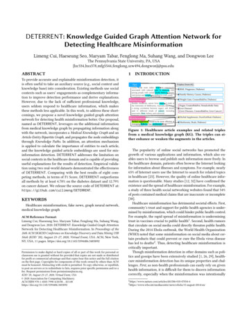
Transcription
Basic Information onStraumann Guided SurgeryStraumann Dental Implant System
The ITI (International Team for Implantology) is academic partner of Institut Straumannin the areas of research and education.
ContentsAbout this guide1. P reoperative planning and guided surgery forStraumann Dental Implant System34 Step 1 – Treatment plan4 Step 2 – Scan prosthesis fabrication4 Step 3 – CT scanning5 Step 4 – Software-based planning and fabricationof the surgical template (open system approach)5 Step 5 – Surgery with Straumann guided instruments& guided implant insertion5 Step 6 – Prosthetic procedures53.5 Guided implant placement353.5.1 Opening the implant package353.5.2 Placing the implant353.6 Soft tissue management394. Product specifications404.1 Sleeve-position implant-length matrix404.1.1 Sleeve-position implant-length matrix forØ 5.0 mm sleeves in the surgical template 404.1.2 Sleeve-position implant-length matrix forØ 2.8 mm sleeves ( narrow interdental spaces)in the surgical template 404.2 Straumann guided drill design2. Planning and clinical solutions62.1 Surgical template62.1.1 Surgical template fixation62.1.2 Sleeves for surgical templates72.1.3 Sleeve positions92.1.4 Surgical template fabrication102.1.5 Surgical template pre-processing102.2 Straumann Guided Surgery concept11 2.2.1 Drill handles for basic implantbed preparation 112.2.2 C-handles for final implant bed preparation 13414.3 Color-coding and labeling of Straumann cuttinginstruments for guided surgery42 4.4 Overview of cutting instruments for guided surgery with depth control434.5 Overview of guided implants444.6 Surgical protocol template for completing manually(to be copied)455. Additional information465.1 Additional information on surgical instruments465.2 Care and maintenance of instruments472.2.3 The surgical protocol for guided surgery145.3 L abeling and color-coding of the StraumannDental Implant System2.2.4 Straumann guided implants155.4 Related documentation502.2.5 Straumann Guided Surgery Cassette165.5 Important guidelines522.2.6 Precautions173. Surgical procedures186. Index543.1 Use of the mucosa punch183.2 B asic implant bed preparation for situations withsufficient interdental space193.3 B asic implant bed preparation for narrowinterdental spaces263.4 Final implant bed preparation283.4.1 Profile drilling for situations with sufficientinterdental space293.4.2 Tapping for situations with sufficientinterdental space313.4.3 Overview guided instruments for final implant bed preparation 34 48
About this guideThe Basic Information on Straumann Guided Surgery for the Straumann DentalImplant System provides dental professionals and related specialists with the essential steps for surgical treatment planning, and procedures for guided surgery.The manual is divided into the following main parts:Preoperative planning and guided surgery for Straumann Dental Implant SystemPlanning and clinical solutionsSurgical proceduresProduct specificationsAdditional informationThe following information is not sufficient to allow immediate use of the StraumannDental Implant System. Knowledge of dental implantology and instruction in thehandling of the Straumann Dental Implant System provided by an operator with therelevant experience and by the brochure for conventional procedures “StraumannDental Implant System: Basic Information on the Surgical P rocedures” (USLIT 100)are always necessary. For detailed information on products supplied by thirdparties, please contact these companies directly.Please note that not all products are available in all markets.Please contact your local Straumann representative for more details.3
1. Preoperative planning and guided surgery for Straumann Dental ImplaStraumann Software systemOpen1. Treatment plan2. Fabrication scan prosthesis4. Software based planningStraumann guided instruments are intended fortreatments planned preoperatively with 3D planningsoftware. They are designed to prepare the implantbed for implants of the Straumann Dental Implant Systemusing surgical templates.NoteFor a template based surgery, the patient’s mouth opening capability needs to be sufficient to accommodate theinstruments for guided surgery.The Straumann planning software complementing theStraumann guided instruments is called coDiagnostiX .For further information, please contact your Straumannrepresentative. However, the open system approach alsoallows for the execution of template-based surgerypreoperatively planned with other planning softwaresystems. For further information, please contact yourStraumann representative.The scan prosthesis is a radiopaque duplicate of the currentsituation or the provisional teeth set-up. It supplies the clinician with additional information for implant planning.When the patient is scanned with the scan prosthesis, thedesired tooth set-up is visible in the CT images.The scan prosthesis is also used to visualize the soft tissuesituation in the planning software. Furthermore, referencemarks (e.g. Guttapercha) are incorporated in the scanprosthesis for the identification of its position in the planningsoftware.The procedure for fabricating the scan prosthesis isdependent on applied software and chosen templatefixation (bone, teeth or mucosa supported). Refer to thedetailed d ocumentation of the software suppliers for furtherinformation. Computer Guided (Static) Surgery can be subdivided intosix main steps (see figure above). They are described in thefollowing. Step 1 – Treatment planDiagnosis and patient specific requests influence the treatment plan. The type of final restoration, patient’s request fora provisional, number of implants and imaging procedureneed to be taken into account for the patient’s treatmentplan for guided surgery.43. CT scanning Step 2 – Scan prosthesis fabrication1. Preoperative planning and guided surgery for Straumann Dental Implant System
ant Systems ys t e mFabrication surgical template5. Surgery with Straumann 6. Prosthetic proceduresguided instruments Step 3 – CT scanningRegardless of imaging technology used, scanning withthe correct parameters is the basis for accurate planningin the software and for correct implant placement.In order to get the optimal scan data, the radiologist andthe patient need to be instructed correctly and scanninginstructions/parameters must be followed according to thesoftware supplier guidelines. tep 4 – Software-based planning andS fabrication of the surgical template (open system approach)Software-based planning allows for implants to be plannedvirtually within the planning software. When completedsuccessfully, the case plan is sent to the surgical templatemanufacturer. The software company may act as thesurgical template manufacturer or the dental laboratory mayfabricate the surgical template depending on the softwareconcept used.NoteIn this step, the surgical template manufacturer ensures thecompatibility with the Straumann guided instruments byutilizing Straumann sleeves for guided surgery positionedaccording to Straumann parameters. tep 5 – Surgery with Straumann guidedS instruments & guided implant insertionAfter fixing the surgical template in the patient’s mouth,the implant bed for Standard, Standard Plus, Tapered Effect,and Bone Level implant lines can be prepared with theguided instruments included in the portfolio of Straumann Guided Surgery Instruments. The surgical protocol, providedtogether with the surgical template, recommends whichinstruments are required to prepare each i mplant site. TheStraumann guided implants allow for insertion through thesurgical template including a physical depth control. Step 6 – Prosthetic proceduresFor the prosthetic procedures, Straumann offers a wide range of solutions. The brochures “Straumann NarrowNeck: Prosthetic Options for Narrow Neck Implants”(USLIT 112), “Straumann synOcta ProstheticSystem: Crown and Bridge Restorations” (USLIT 187),“Straumann Solid Abutment Prosthetic System:Cement-retained Crowns and Bridges with the SolidAbutment System” (USLIT 045) and “Straumann Bone LevelImplant Line: Basic Information on the Prosthetic Procedures”(USLIT 232) describe in detail the prosthetic workflow for therespective implants to be restored.1. Preoperative planning and guided surgery for Straumann Dental Implant System5
2. Planning and clinical solutions2.1 Surgical template2.1.1 Surgical template fixationBone-, mucosa- and teeth-supported surgical template fixations (see figures below)are possible depending on the clinician’s preferences and the planning system used.Bone-supportedMucosa-supportedNoteIn order to stabilize the surgical template, it can additionally be fixed with fixation pins (see chapter 3), fixation screws, or it can be positioned on temporaryimplants.62. Planning and clinical solutionsTeeth-supported
2.1.2 Sleeves for surgical templatesDepending on the anatomical situation and the plannedaxis of adjacent implants, two different sleeve diameters areavailable.Ø 5.0 mm sleeves for regular situations with sufficientspace for sleeve placementØ 2.8 mm sleeves for narrow interdental spaces5.0 mm inner diameter2.8 mm inner diameterSleeve collision due toinclination or narrowinterdental spaceUse a Ø 2.8 mmsleeve insteadFurthermore, the sleeves are available in two different designs:cylindricalcylindrical with an additional rim at the top (T-sleeve)Which sleeve design is used depends on the surgical template manufacturer. The graphics in this brochure showthe cylindrical sleeves as example (see specifications in thefollowing table).2. Planning and clinical solutions7
ArticleArt. No.Sleeve innerdiameterSleeve outer diameterSleeve heightUse of drillhandled 5.0 mmDmin 5.7 mmDmax 6.3 mmH 5.0 mmyesd 2.8 mmDmin 3.2 mmDmax 3.8 mmH 6.0 mmØ 5.0 mmSleeve034.050V4DmaxDmindH034.052V4dØ 2.8 mmSleeveDmaxDminno(Direct guidance ofmilling cutters andguided drillsHØ 2.8 mm)Ø 5.0 mmT-sleeve034.053V4DcollarDminDmin 5.7 mmDcollar 7.0 mmDmax 6.3 mmH 5.0 mmh 4.5 mmd 2.8 mmDmin 3.2 mmDcollar 4.4 mmDmax 3.8 mmH 6.0 mmh 5.5 mmdd 5.0 mmHyesDmaxh034.055V4dØ 2.8 mmT-sleeveDcollarDminHDmaxh82. Planning and clinical solutionsno(Direct guidance ofmilling cutters andguided drillsØ 2.8 mm)
2.1.3 Sleeve positionsThe system allows for flexible sleeve placement in the surgical template. The three distinct sleeve positions are2.0 mm (H2), 4.0 mm (H4), 6.0 mm (H6) above bonelevel (see figure).Ø 5 mm sleeve2.0 mmH44.0 mmH66.0 mmH26.0 mmsleeve height5.0 mmsleeve heightH2Ø 2.8 mm sleeveH42.0 mmH64.0 mm6.0 mmWhile determining the corresponding sleeve position foreach implant in the planning software, the following requirements need to be considered for favorable conditions duringsurgical procedures.The surgical template fixation (mucosa-, bone- or teeth supported) and the mucosa thickness determine thesleeve position.The sleeve position in the surgical template must allow forample access for instrument irrigation.Sleeve contact with tissue must be avoided.NotesPlace the sleeve as close to the bone / soft tissue as anatomic conditions allow in order to reduce overallinstrument height.2. Planning and clinical solutions9
2.1.4 Surgical template fabricationThe surgical template must allow for proper irrigation of the surgical site. For this purpose, windows can be included inthe surgical template.For a correct fit of the cylinder of the handles in the sleeve(see chapter 2.2.1) remove additional material around thesleeve.CautionEnsure the sleeves are firmly fixed into the surgical template.Radial and axial load on the sleeves must be avoided tohelp ensure proper retention of the sleeves in the surgicaltemplate and reduce abrasion of the rotating instrumentsin the sleeve.Prior to starting the surgical procedures, evaluate the fitand stability of the surgical template on the model and inthe patient’s mouth as well as size and localization of theopenings for irrigation after receiving it from the manufacturer. Verify if the position and orientation of thesleeves in the surgical template correspond with the preoperative plan. Check product documentation (ifavailable) from the surgical template manufacturer.2.1.5 Surgical template pre-processingFor disinfection/sterilization of the surgical template beforesurgery use an appropriate liquid chemical disinfectant (e.g.betadine) or a sterilizing agent that follows the instructionsfrom the template manufacturer. Do not damage the materialof the surgical template.102. Planning and clinical solutions
2.2 Straumann Guided Surgery concept2.2.1 D rill handles for basic implant bed preparationStraumann drill handles direct milling cutters and guideddrills based on the sleeve-in-sleeve concept (see adjacentfigure). The cylinder of the drill handle is inserted into thesleeve (Ø 5.0 mm) fixed to the surgical template. For eachinstrument diameter, Ø 2.2 mm, Ø 2.8 mm, Ø 3.5 mmand Ø 4.2 mm, an ergonomic drill handle is available.Drill handlewith cylinders fordrill guidanceSleevefixed to the surgicaltemplateEvery drill handle features one cylinder with an additionalheight of 1.0 mm at one end and a second cylinder withan extra cylinder height of 3.0 mm at the other end (seefigure below). 1.0 mm 3.0 mm 2.0 mm inosteotomy depthThe surgical protocol (see chapter 2.2.3) lists which cylinderof the drill handle ( 1.0 mm, 3.0 mm) should be used foreach implant.2. Planning and clinical solutions11
1 mmFor identification during surgery, Straumann drill handlesfor guided surgery are color-coded and symbol-marked(see following figure).m 3 mArt. No.Instrumentdiameter 1.0 mm1.0 mm12034.150Ø 2.2 mm034.250Ø 2.8 mm034.450Ø 3.5 mm034.650Ø 4.2 mm2. Planning and clinical solutions 3.0 mmDrill handlecylinderColor-codingand symbol3.0 mm
2.2.2 C-handles for final implant bed preparationStraumann C-handles for final implant bed preparation arealso designed according to a sleeve-in-sleeve concept. Thecylinder of the C-handle is inserted into the sleeve (Ø 5.0 mmonly) fixed to the surgical template. Each C-handle corresponds to one distinct sleeve position (H2, H4 and H6) asshown in the chart below.Art. No.ArticleSleeve position034.750C-handle H2H22.0 mm above bone level034.751C-handle H4H44.0 mm above bone level034.752C-handle H6H66.0 mm above bone levelThe Straumann C-handles direct guided profile drills andguided taps (see figure).H2034.752H4H6034.751034.7504.0 mm6.0 mm2.0 mm2. Planning and clinical solutions13
2.2.3 The surgical protocol for guided surgeryThe implant bed preparation with guided instruments followsthe surgical protocol normally delivered together with thesurgical template by the manufacturer or exported from theplanning software. Based upon the virtual plan wheresleeve dia meter and sleeve position were selected, the surgical protocol provides the correct combination of drill handle cylinder and Straumann guided instruments to be usedfor each implant. The following chart shows an example ofa surgical protocol in this brochure.Basic implant bedpreparationImplantpositionImplantArt. uideddrillCylinderof drillhandleProfiledrillC-handleTap21033.052GSP, RNØ 4.1 mm,10 mmSLActive5.0 mmH4Ø 3.5 mm RN,Ø 4.1 mmH4SP,Ø 4.1 mmlong,guidedLegend:4 mm14Final implant bedpreparation2. Planning and clinical solutions 1.0 mm
CautionVerify if the surgical protocol corresponds to your preoperatively defined treatment plan before you start surgery.All Straumann guided drills and guided profile drills (seechapter 4.4) feature a collar. In order to reach the required depth for each implant, drilling must always becontinued until the collar hits the cylinder of the handle.The combination of guided instruments listed in the surgical protocol is recommended under this presumption.The surgical protocol represents a suggestion for yourtreatment. The clinician is responsible for adjusting thesurgical protocol in case the clinical situation varies fromthe virtual planning.NotesThe surgical protocol might differ in appearancedepending on the planning software used.Refer to the sleeve-position implant-length matrix in theproduct specifications (see chapter 4.1) for consistencycheck.2.2.4 Straumann guided implantsStraumann guided implants can be inserted fully guidedthrough the Staumann sleeves with an inner diameter of5.0 mm. For physical depth control, the stop key engageswith the transfer piece.Stop keyTransfer pieceThe only difference between the guided and standard Straumann implants is the transfer piece. The implant itselfand the prosthetic components are identical.Only select Straumann implants are available as guidedimplants. Please see page 44 for the current portfolio ofStraumann Guided Implants. Straumann Bone Level implantswith a Narrow Connection are not available as GuidedImplants.2. Planning and clinical solutions15
2.2.5 Straumann Guided Surgery CassetteThe Straumann Guided Surgery Cassette (see figure) isused for the secure storage and sterilization of the surgicalinstruments and auxiliary instruments of the Straumann Dental Implant System (see chapter 5.2).The color-coded sequences on the cassette help ensure areliable working process during surgery. Clear illustrationsallow for checking the arranged instruments for correctnessand completeness at a glance. The instruments are positioned securely in the silicone grommets for sterilization andstorage.162. Planning and clinical solutions
2.2.6 PrecautionsGuided instruments must only be used together with the corresponding sleeves fixed in templates and handles.Inspect the instruments for operational reliability prior toeach surgery and replace if necessary.Cutting instruments must not rotate during insertion intoand removal from sleeves or handles (see adjacent figure).Avoid lateral pressure on instruments which may lead todamage of the instruments, the cylinder of the handle andthe sleeve. Hold the drill handle while drilling.During and after implant bed preparation, the patient‘smouth must be thoroughly rinsed and aspirated.Pilot and twist drills have an apical overlength (up to0.4 mm) at the drill tip compared to the insertion depth ofthe implant.Use intermittent drilling technique.Use handles only in combination with guided instruments,as indicated on the package labeling.Do not bend handles.No rotationOnly start rotationwhen insertedEnsure ample cooling of cutting instruments with sterilesaline solution (NaCl). This applies for instruments usedwith handles as well.Guided instruments must not be used in combination withdrill sleeves with collar (049.810V4), thermoplastic drilltemplates (040.526 and 040.527) or drill stops(040.460, 040.454S-040.457S).2. Planning and clinical solutions17
3. Surgical procedures3.1 Use of the mucosa punchAs an option, the mucosa punch can be used through the 5.0 mm sleeves beforeusing the milling cutter. The following table lists the available mucosa puncheswith its specifications.Art. No.Article034.010Mucosa punch, Ø 3.4 mm, guided15034.011Mucosa punch, Ø 4.0 mm, guided15034.012Mucosa punch, Ø 4.7 mm, guided15The three depth marks indicate the distance from bone levelto the upper border of the respective sleeve (H2, H4, H6).182. Planning and clinical solutionsMax rpm.
3.2 B asic implant bed preparation for situations withsufficient interdental spaceAfter opening the gingiva, position the surgical template. Verify the fit and stability of the surgical template before starting with the osteotomy preparation.Start the basic implant bed preparation with preparing the alveolar ridge (Step 1on page 20). After that, the implant bed preparation with pilot and twist drillsfollows (Steps 2–5 beginning on page 21) according to the endosteal implantdiameter chosen in the preoperative planning.Basic implant bedpreparationFinal implant bedpreparationImplantpositionImplantArt. No.ImplantSleeveheightSl
2.2.4 straumann guided implants 15 2.2.5 straumann Guided surgery cassette 16 2.2.6 Precautions 17 3. Surgical procedures 18 3.1 Use of the mucosa punch 18 3.2 Basic implant bed preparation for situations with sufficient interdental space 19 3.3 Basic implant bed preparation for narrow i