Transcription
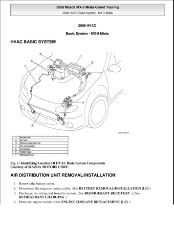
Basic information on theStraumann Variobase Abutment.1
Straumann is the industrial partner of the ITI (International Team forImplantology) in the areas of research, development, and education.
Contents.1. Introduction 1.12.3.5.2General Information 32.12.22.32.43345Introduction to the Straumann Variobase Abutment Technical requirements System overview Product characteristics Restoration, design and finishing 3.13.1.13.23.2.13.2.2 3.2.33.2.43.33.44.Purpose of this guide 2Preparation Fabrication of the master castDesign and fabrication of a coping/crown Scanning and designing with a scanbodyScanning and designing with a wax-upMillingFinishing of the coping/crown in dental laboratoryBonding Insertion (dentist’s office) 6667789101012Auxiliaries and instruments 134.14.24.3131313SCS Screwdrivers Ratchet Polishing aids and analog holder Important guidelines 141
1. Introduction.1.1Purpose of this guideThis guide was created for dental technicians and dentists working with the Straumann Variobase Abutmentfor designing screw-retained or cement-retained customized abutments and cement-retained bridges (viamesostructure). It provides step-by-step information on working with the Straumann Variobase Abutment. Warning/Pre-CautionFailure to follow the procedures outlined in these instructions may harm the patient and/or lead to any or allof the following complications: Aspiration or swallowing of a component Breakage InfectionNoteImplant-borne superstructures require optimal oral hygiene on the part of the patient. This must be consideredby all involved parties when planning and designing the restoration.Consult the brochure Basic Information on the Surgical Procedures – Straumann Dental Implant System forinformation on indications and contraindications of Straumann implants, such as the required minimumnumber of implants, implant type, diameter and loading protocols.2
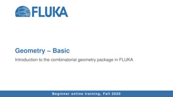
2. General information.2.1Introduction to the Straumann Variobase AbutmentThe Straumann Variobase Abutment provides dental laboratories with the flexibility to create customizedabutments through their preferred workflow. In addition, the Straumann Variobase Abutment comes withthe benefit of the original Straumann connection and the unique Straumann engaging mechanism.For intended use and indications for use, please refer to the instructions for use.2.2 Technical requirements for digital workflowStraumann Variobase Implant KitTo facilitate the precise design of the interface between theStraumann Variobase Abutment and the coping, a specific digitalStraumann Variobase Implant Kit is required with your softwareplatform. The kit consists of an open STL file containing the requiredcoping geometry.The Straumann Variobase Implant Kit is available from Straumannon request.NoteThe Straumann Variobase Implant Kit only provides the geometry of the coping for the Straumann VariobaseAbutment.SoftwareTo design using the Straumann Variobase Abutment for digital workflows, CAD software containing theStraumann Variobase Implant kit can be used. Please follow the instructions of the CAD software provider.Please contact Straumann for more information regarding availability.MillingOnce the coping is designed using CAD software, the resulting STL file is sent to Straumann.Milling is available for customers with the Straumann CS2 scanner or the CARES prosthetic app for DentalWings scanners.3
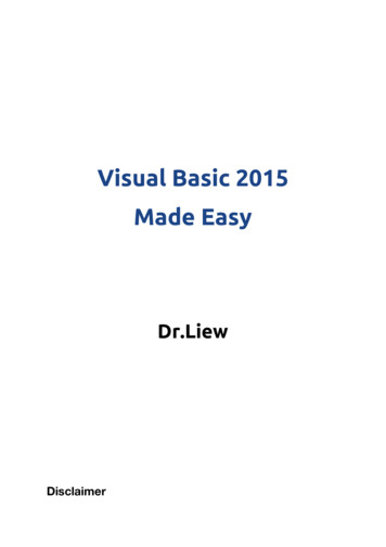
2.3 System overviewThe Straumann Variobase Abutment covers the following Straumann implant Burn-outcopingsAuxiliaryscrews1Article numbers ending in V4 or in -04 contain 4 burn-out copings in one pack.4
2.4Product characteristicsReliability The original Straumann implant-abutment connection Strong retention of the coping with a patented 2 engagingmechanism Extra bonding surface with 4 camsEfficiency Variobase STL data available for various CAD software platforms Easy and precise wax-up process with accurate burn-out copings Compact base dimensions for design flexibility Simplified bonding process Skip the sandblasting process 4 cams facilitate precise positioning of the copingCost-effectiveness Use the CAD software of choice, and send to Straumann2Patent pending.5
3. Restoration, designand finishing.3.1PreparationPrerequisites The tooth shade has been identified The impression has been taken Shade information and impression have been sent to the dental lab3.1.1 Fabrication of the master castTo ensure high-quality restorations, fabricate the master castusing standard methods and type-4 dental stone (ISO 6873).Adhere to the following requirements: Use new, undamaged and original Straumann implant analogs Embed the implant analogs in the stone; the analogs must notmove in the model Always use a gingival mask to ensure the emergence profile isoptimally contoured Use scannable material for the gingival mask6
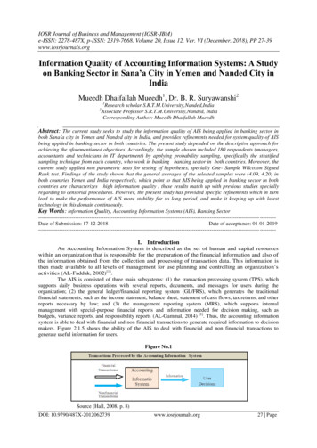
3.2 Design and fabrication of coping/crown3.2.1 SCanning and designing with a scanbodyStep 1 – AssemblingCheck for proper fit of the scanbody in the analog andhand-tighten the self-retaining screw (maximum 15 Ncm). Use theStraumann SCS Screwdriver to fix the post in the analog. Checkagain for proper fit and for any rotational or vertical looseness. If asingle-tooth restoration is planned, orient the angled surface of thescanbody buccally (not adjacent to the approximal tooth). Avoidany contact of the scanbody to the proximal teeth.Step 2 – Scanning and modelingFollow the software provider’s instructions on how to scan andrecognize the scanbody. Design the coping or crown following thesoftware provider’s instructions.7
3.2.2 SCANNING AND DESIGNING WITH A WAX-UPStep 1 – Placing of the Straumann Variobase AbutmentPlace the Straumann Variobase Abutment on the analog and handtighten the screw (maximum 15 Ncm). Use the Straumann SCSScrewdriver to place the abutment on the analog. Check again forproper fit and for any rotational or vertical movement.Step 2 – Assembly of the burn-out copingAttach the burn-out coping to the Straumann Variobase Abutmentand check for proper fit.NoteWorking with the burn-out coping supports a clean and sharpedged finish of the screw channel and a good fit to the S traumannVariobase Abutment.NoteThe burn-out coping should be free of any rotational or verticalmovement.Step 3 – Shortening of the burn-out copingShorten the burn-out coping to the height of the occlusal planeaccording to the individual circumstances.NoteEnsure that the shortened burn-out coping still covers theStraumann Variobase Abutment completely.8
Step 4 – Wax-upContour a wax-up according to the individual anatomical situation.Note Make a reduced anatomic design or a full-contour designdepending on the indications of the dental material used Ensure that the wax layer on the abutment is sufficiently thick Respect the minimal wall thickness of the respective dentalmaterial used according to the manufacturer’s instructionsStep 5 – Scanning and ModelingFollow the software provider's instructions on how to scan andrecognize the wax-up. Complete design of the coping following thesoftware provides instructions.3.2.3MillingPreparation for millingTransfer design data to Straumann by following the instructions ofyour CAD software provider.Note Use the proper settings per material following the instructionsof your CAD software provider In lab milling or third party milling is not indicated and will voidthe warranty9
3.2.4 FINISHING of the coping/crownin dental laboratoryStep 1 – Finishing of the coping/crownUse standard procedures to finalize the coping or crown.Note The coping or crown to be bonded to the Straumann Variobase Abutment must be finalized before bonding For cement-retained restorations, the crown can be made andfinalized after the bonding step3.3 BondingStep 1 – Seating on master modelSeat the Straumann Variobase Abutment on the implant analog inthe master model with a screw (hand-tight). Seal the screw channelwith wax to prevent excess cement from flowing into the screwchannel.NoteDue to its patented* engaging mechanism, it is not necessary tosandblast the Straumann Variobase Abutment to obtain a strongbond.Always bond on the master model to ensure precise seating ofthe coping or crown on the Straumann V ariobase Abutment.Due to the symmetrical nature of the four cams, confirm theposition of the crown according to the individual patient anatomyprior to bonding.* Patent pending.10
Step 2 – BondingApply self-adhesive dental cement 3 on the Straumann Variobase Abutment. Follow the cement manufacturer’s instructions. Bondthe coping to the Straumann Variobase Abutment.Note Immediately remove excess cement from the abutment. Polishthe lower margin of the coping after the cement has dried Always use a polishing aid to protect the abutment’s prosthetic connection Warning Do not fire the abutment after bonding3Tested with Panavia F2.0 resin cement by Kuraray and a zerion (zirconium dioxide)coping by Straumann.11
3.4Insertion (dentist’s office)The final restoration is fixed on the master cast before it is delivered to the doctor’s office.Step 1 – Preparation Remove the healing cap or temporary restoration Remove the superstructure from the master cast and unscrew the abutment from the analog Clean and dry the interior of the implant and the abutment thoroughlyNoteAlways ensure that surfaces of threads and screw heads are clean and that a new screw is used for the finalrestoration.Step 2 – Final insertionOption A: Screw-retained final restoration Position the sterilized Straumann Variobase Abutment withthe coping in the implant. Tighten the screw to 35 Ncm usingthe SCS Screwdriver together with the ratchet and the torquecontrol device Close the SCS screw channel with cotton and sealing compound(i.e. gutta-percha). This allows for later removal of theStraumann Variobase Abutment in case a crown replacementshould be requiredOption B: Cement-retained final restoration Position the sterilized Straumann Variobase Abutment in theimplant. Tighten the screw to 35 Ncm using the SCS Screwdrivertogether with the ratchet and the torque control device Close the SCS screw channel with cotton and sealing compound(i.e. gutta-percha). This allows for later removal of theStraumann Variobase Abutment in case a crown replacementshould be required Cement the superstructure to the abutment Remove excess cement12
4. Auxiliariesand instruments.4.1 SCS ScrewdriversArt. No.ArticleDimensionsMaterial046.400SCS Screwdriver forratchet, extra shortLength 15 mmCronidur 30046.401SCS Screwdriver forratchet, shortLength 21 mmCronidur 30046.402SCS Screwdriver forratchet, longLength 27 mmCronidur 304.2RatchetArt. No.046.1194.3ArticleRatchet includesservice instrumentDimensionsLength 84 mmMaterialStainless steelPolishing aids and analog holderArt. No.ArticleDimensionsMaterial046.245Polishing protectorfor RN synOcta Copings, transocclusalscrew-retainedLength 15 mmStainless steel025.2920025.2920-04NC Polishing aidLength 16 mmStainless steel025.4920025.4920-04RC Polishing aidLength 16 mmStainless steel046.239Analog holderLength 105 mm Al/Steel13
5. Important Guidelines.IMPORTANT GUIDELINESPlease notePractitioners must have appropriate knowledge and instruction in thePlease notehandlingPractitionersof the StraumannCADCAM productsorandotherStraumannmust have appropriateknowledgeinstructionin for usingproductsthe StraumannProductsof the Straumannor other Straumannsafely andproperlyin accordancewith thefor use. Productsproducts(“StraumannProducts”)for instructionsusing the StraumannExplanation of the symbols on labels andinstruction leafletsExplanation of the symbols on labels and instruction leafletsBatchcodeBatchcodesafely and properly in accordance with the instructions for use.CataloguenumberCataloguenumberThe Straumann Product must be used in accordance with the instrucThe Straumann Product must be used in accordance with thetions for use provided by the manufacturer. It is the practitioner’sinstructions for use provided by the manufacturer. It is the practitioner’sresponsibility to use the device in accordance with these instructionsresponsibility to use the device in accordance with these instructionsfor use andto anddetermine,if theif devicefits fitsto thefor useto determine,the deviceto theindividualindividual federallawlawrestrictsCaution:federalrestricts orderorderof a dentalof aprofessional.dental professional.Do Donotnotre-usere-useThe StraumannProductsare partof overallan overallconceptandandmustmust beThe StraumannProductsare partof ngoriginalcomponentsused only in conjunction with the corresponding original componentsand instruments distributed by Institut Straumann AG, its ultimateand instruments distributed by Institut Straumann AG, its ultimateparent company and all affiliates or subsidiaries of such parentparent company and all affiliates or subsidiaries of such parent companycompany (“Straumann”), except if stated otherwise in this document(“Straumann”),if statedotherwisein this documentin theor in theexceptinstructionsfor usefor the or the maderespectiveStraumannIf use of prodIf useproductsby thirdparties isProduct.not recommendedbyStraumannthis documentor in the respectiveinstructions foructs madeby thirdinpartiesis not recommendedby Straumannin use,thisanyorsuchuse respectivewill void anywarranty or forotherobligation,ordocumentin theinstructionsuse,any suchexpressuse willvoid any implied,warrantyoforStraumann.other obligation, express or implied, of Straumann.AvailabilityAvailabilitySome of the Straumann Products listed in this document may not beSome of availablethe StraumannProducts listed in this document may not bein all countries.available in all countries.CautionCaution In addition to the caution notes in this document, our products mustbe tosecuredagainstnotesaspirationused intraorally.In additionthe cautionin thiswhendocument,our products must besecured against aspiration when used intraorally.ValidityUpon publication of this document, all previous versions areValidity superseded.Upon publication of this document, all previous versions are superseded.DocumentationFor detailed instructions on the Straumann Products contact yourDocumentationStraumann representative.For detailedinstructions on the Straumann Products contact yourStraumann representative.Copyright and trademarksStraumann documents may not be reprinted or published, in wholeCopyrighttrademarksorandin part,without the written authorization of Straumann. Straumann documentsmayothernot trademarksbe reprintedor published,whole orStraumannand/orandlogos from inStraumannmentionedareauthorizationthe trademarksoforregistered trademarksofin part, withoutthehereinwrittenStraumann.Straumann StraumannHoldingAGand/oritsStraumann affiliates.and/or othertrademarksandlogosfrommentioned hereinare the trademarks or registered trademarks of Straumann Holding AGand/or its affiliates.14Non-sterileNon-sterileReferto packageinsertReferto packageinsert0123Straumann Products with the CEStraumann Products with the CE mark fulfillmark fulfill the requirements of thethe requirements of the Medical DevicesMedicalDevicesDirectiveDirective93/42EEC 93/42 EECConsultinstructionsConsultinstructions forfor useuseManufacturerManufacturer
Straumann USA, LLC 2014. All rights reserved.Straumann and/or other trademarks and logos from Straumann that are mentioned herein are the trademarks or registered trademarks of Straumann Holding AGand/or its affiliates. All rights reserved.3/14Straumann North American HeadquartersStraumann USA, LLC60 Minuteman RoadAndover, MA 01810Phone 800/448 8168 (US) 800/363 4024 (CA)Fax978/747 2490www.straumann.us www.straumann.caUSLIT 503International HeadquartersInstitut Straumann AGPeter Merian-Weg 12CH-4002 Basel, SwitzerlandPhone 41 (0)61 965 11 11Fax 41 (0)61 965 11 01
The Straumann Variobase Implant Kit is available from Straumann on request. Note The Straumann Variobase Implant Kit only provides the geometry of the coping for the Straumann Variobase Abutment. software To design using the Straumann Variobase Abutment for digital workflows, CAD software containing the