Transcription
NEODENT GUIDED SURGERYMANUALGrand Morse ConnectionHelix Implant
GRANDPOSSIBILITIESWITH A LIMITLESSSOLUTION.GRAND MORSE NEODENT GUIDED SURGERY.4
5
6
CONTENTS1. CLINICAL STEP BY STEP OFGRAND MORSE NEODENT GUIDED SURGERY (GM NGS)81.1. Diagnostic / Data Acquisition81.2. Virtual Planning81.3. Surgical Guide Production81.4. Surgical procedures with GM NGS System82. GM NGS - CONCEPT92.1. General Aspects92.2. Surgical Guide - Types of Support92.3. GM NGS Fixation Clamps102.4. GM NGS Sleeves112.5. GM NGS Drill Guide133. GM NGS SURGICAL KIT143.1. GM NGS Punch (optional)153.2. GM NGS Drills153.3. GM NGS Connections173.4. GM NGS Stabilizer (optional)184. CLINICAL WORKFLOW194.1. Narrow Sleeve Diameter194.2. Regular Sleeve Diameter204.3. Wide Sleeve Diameter217
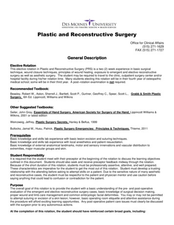
1. CLINICAL STEP BY STEP OF GRAND MORSE NEODENT GUIDED SURGERY (GM NGS)Neodent Guided Surgery (NGS) Instruments are intended for procedures with 3D planning software through Cone Beam ComputerTomography (CBCT) images. They are designed to prepare the osteotomy and perform the implant placement of Neodent GM implants incombination of surgical guide including the Neodent Sleeves.1. Diagnostic/Data Acquisition2. Virtual Planning3. Surgical Guide Production4. Surgical ProcedureImpression andPlanning andSurgical guide preparation andSpecific tools for guidedCBCT scanningimplant selectionsleeve placementsurgery1.1. Diagnostic / Data AcquisitionanChairside diagnostics and patient-specific requests influence on treatment plan. It is important to take into account: bone volume,bone density; anatomy of the area to be restored; type of restoration; type of loading, number of implants; esthetic and functional factors;and any other important considerations supporting the treatment plan for guided surgery.Regardless of imaging technology, a CBCT scan (respecting the correct right parameters) is the basis for a precise digital plan andfor accurate implant placement. In order to obtain the optimal scan data, the radiologist and the patient must be correctly instructed andscanning instructions/parameters must be followed according to the software manufacturer instruction for use (IFU). A dental impression isrequired and could be done conventionally or digitally.*Note: For guided surgical procedures, the patient’s mouth opening capability needs to be sufficient to accommodate the instruments of guided surgery.1.2. Virtual PlanningThe 3D dataset (DICOM) can be imported directly into commercially available planning softwares (e.g. coDiagnostiX) and overposedwith the dental impression taken from the scanners (STL file). The implant is positioned with respect to the patient’s anatomy and desiredprosthetic outcome.1.3. Surgical Guide ProductionOnce the virtual planning is completed successfully, the treatment plan is sent to the surgical guide manufacturer. The softwaremanufacturer or the dental laboratory may fabricate the surgical guide depending on the software concept used.*Note: In this step, the surgical guide manufacturer ensures the compatibility with the NGS Instruments by using Neodent sleeves for guided surgery, positioned according to Neodent parameters.1.4. Surgical procedures with NGS SystemAfter having fixed the surgical guide in the patient’s mouth, optionally with the Neodent Fixation Clamp, the osteotomy for theNeodent GM implant line can be prepared with the Neodent Guided Surgery Instruments included in the Neodent Guided Surgery Kit. The surgical protocol, provided together with the surgical guide, recommends which instruments are required to prepare each implant site. NGSinstruments allow guided insertion of implants, through the surgical template including depth control (marks on the drills - guided surgery GMconnection - contra-angle).8
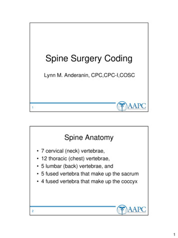
2. GM NGS CONCEPTGuided DrillConventional Drill2.1. General aspectsThe patient’s mouth opening ability in the region of the implant should be sufficient forproper use of GM NGS drills and connections. The drills and connections used in guided surgerytechniques need to compensate for the soft tissue thickness, the sleeve height and, therefore,have considerably greater lengths than the instruments used in conventional techniques. A limitedmouth opening may turn difficult to install implants in guided surgery procedures.The sleeve size is standardized in 4 mm. Therefore, GM NGS system presents 9 or 11 mm(H11- long) between the upper part of the sleeve and the implant platform, which provide enough6 mmoptions of height for soft tissue thickness and subcrestal implant placement.4 mm4 mmMucosa thicknessup to 5 mm9 mmMucosa thicknessup to 7 mm11 mmIn case of osteotomy to regularize bone ridge or multiple extractions the immediate installation of implants are contraindicatedwith guided surgery technique due to bone remodeling after these procedure. The physiological ridge reduction process can lead to loss ofstructure that would be used previous implant installation planning.2.2. Surgical guide - Types of supportSeveral types of supports for surgical guides are commercially available (see figures) according to customized surgical indication,considering software planning and guide manufacturer features. All are possible, depending on the dentist’s preferences, the planningsoftware used and surgical guide manufacturer.Mucosa supported surgical guide Teeth supported surgical guide9
2.3. GM NGS Fixation ClampsGM NGS Fixation Clamps have been designed to ensure stability and fixation of the surgical guide. They are used to maintain thesurgical guide at its position from throughout the surgery. Drilling speed: 500-800 rpm. No drill handle is required for the drilling procedure of the Fixation Clamp. Use the intermittent drilling technique until the physical stop of the drill 1.3 mm. After the osteotomy, fully engage the Fixation Clamp until the physical stop.*Note: Procedure not necessary for all cases, specially indicated for fully edentulous patients.103.395Guided SurgeryDrill 1.3 mm3.11.5Sleeve of Setter forGuided Surgery (yellow)125.13820 mm7.5Indicated for the placementof the Fixation Clamp.20 mm125.100Guided SurgeryFixation Clamp2.5In order to ensure stability, the Fixation Clamp should be placed in an area with a sufficient and adequate bone quality.The Neodent Sleeve of Setter for Guided Surgery (Fixation clamp) should be surrounded with enough surgical guide material foroptimal retention. Additionally, the number of Fixation Clamps has to be adapted to the patient anatomy, type of surgical guide,number and position of implants (examples of recommended position, see figures).10
2.4. GM NGS SleevesThe GM NGS Sleeve is selected according to the mesio-distal space and implant diameter. During the digital planning, sleevepositions have to be evaluated in order to avoid collision. GM NGS offers a comprehensive range of sleeve diameters for optimizing sleeveplacement.(1) NARROW;(2) REGULAR;(3) WIDE.(3)(2)(1)Sleeves measurements according to implant diameters indications.(A)(B)(D)(C)ModelIndicationHelix GM : Ø 3.5Drive GM : Ø 3.5(A) Diameter ofthe Stop (mm)(B) InternalDiameter (mm)(C) BodyDiameter (mm)(D) Height blue)Helix GM : Ø 3.5/3.75/4.0/4.3Drive GM : Ø 3.5 / 4.3Helix GM : Ø 5.0/6.0Drive GM : Ø 5.0Wide(green)11
In narrow dental spaces, the Narrow Sleeve 3.5 mm can be used to prevent sleeve collision.The GM NGS System allows flexible height sleeve position in the surgical guide. The two sleeve positions are 5 mm (H9) or 7 mm(H11), considering 9 and 11 mm from the upper part of the sleeve to the implant platform. For implant length of 18 mm a partial NGStechnique is indicated.Drill Guide in aDrill Guide in a!Regular SleeveConsider 2 mmRegular Sleeveof Drill Guidethickness11 mm9 mm5 mm127 mm
2.5. GM NGS Drill GuideWith an ergonomic design, the GM NGS Drill Guides are based on the reduction sleeve concept (see image below). The cylinder ofthe drill guide is inserted into the sleeve fixed in the surgical guide.GM NGS Drill Guides are color-coded according to the sleeve in which they should be placed and are laser marked with thecorresponding drill diameter. The drill guide must be placed into the guide sleeves during the drills instrumentation.Drill DiameterImplant DesignDrill Guide Color Coding13
3. GM NGS SURGICAL KITThe GM NGS Surgical Kit (see figure) has been manufactured using autoclavable polymer. It is used for secure storage andsterilization of surgical and auxiliary instruments. For instructions on cleaning and sterilization procedures, please refer to the correspondentIFU at ifu.neodent.com.br, using the article number in the search field. One kit for all bone types. Color-coded sequences help for a reliable working process. Clear illustrations supports for checking the proper set up of instruments. Secured holding of the instruments in the silicone grommets for sterilization and storage.ConvenientCompleteHelix and Drive Grand MorseColor-coded instruments andImplants portfoliosymbol-marked Flexible2 sleeve height positionsNeodent Guided Surgery Kit for Grand Morse Guided implantinsertionGuided bedpreparationCompatible with major guided surgery softwareFor more information on software compatibility please go onwww.neodent.com.br/ngs14
3.1. GM NGS Punch (optional)The punch (mucosa extractor) is a optional surgical instrument with a contra-angle fitting on one edge and a cutting cylindricalformat on the other. Its indication is for circular incision in the mucosa before bone bed preparation through the guided surgery technique.The punches are color-coded according to the diameter of the sleeve they should be used with: narrow (purple), regular (blue) or wide (green).NarrowRegularWide103.429103.430103.431The indicated number of rotations per minute (rpm) for drilling is 60 rpm.3.2. GM NGS DrillsGM NGS Drills have been exclusively designed for a guided surgery procedure in combination with a surgical guide including the GMNGS Sleeves. The drills have to be used together with the corresponding drill guides and sleeves fixed in the surgical guide.15
The drills are of the same format as the ones needed to install a Helix or Drive GM implant in the conventional workflow, howeverthe length is increased for the guided system. The use of the depth probe is recommended for controlling instrumentation depth. The drills aredivided into three types according to its function:1- Tapered Guided Surgery Drills are indicated to prepare the osteotomy, following the sequence based on implant type and diameter,as chosen in the preoperative plan.2- Tapered Guided Surgery Contour Drills are especially indicated as supplementary instruments for osteotomy when placing HelixGM implants in bone types I and II. There are different tapered contour drills to be selected according to implant diameter. These drills are usedonly on bone types I and II, connected to the contra-angle. This step is intended to keep the insertion torque at a desirable level in bone typesI and II. The symbol is seen in the drill number and also on the drill guide for this drill.3- Pilot Guided Surgery Contour Drills are employed to prepare the bone around the coronal area of the implant. For bone types I andII preparation, pilot drills help position the platform of GM implants according to the bone bed. Pilot drills are optional in bone types III and IV.16 mm16 mm13 mm11.5 mm10 mm8 mm13 mm11.5 mm10 mm8 mmPhysical Stop1- Tapered Drill2- Tapered Contour DrillDrilling height81011.51316Real height (mm)192122.524273- Pilot DrillGM NGS Drills : The maximum rotation speed used for all drills is 800 rpm for bone types III and IV and 1200 rpm for bone types I and II. Depth lines to ensure depth visualization control and drilling flexibility (H9 or H11). Designed to improve the irrigation, reducing bone heating. Pilot Drills: Start drilling after having inserted completely the drill into the sleeve and does not go with drill guide.* Note: 18 mm-long GM implants are indicated for partial NGS technique.16
3.3. GM NGS ConnectionsNeodent GM implants were developed to begin placement with contra-angle or manually, and finished with the torque wrench. Themaximum recommended rotation speed for implant installation is 30 rpm, with a torque of 32 Ncm.GM NGS Connections fit the sleeve in the surgical guide and ensure for fully-guided implant insertion, providing physical depthcontrol. It allows subcrestal implant placement, due to the consistency of diameters between connection and implant. The dimples indicatesthe position of the Internal Exact, turning the prosthetic workflow more practical, as it shows the orientation in which the abutment shouldbe installed.GM NGS Connections allows for fully-guided insertion of GM Implants through color-coded GM NGS Sleeves and ensures the rightpositioning with physical depth control. There are two models of GM NGS Connections: For Contra-angle: to capture the implant from the packaging and start the installationAll connections come withExact dimples to guide implantinstallation according toprosthetic rehabilitation.Physical Stop105.139105.140105.141NarrowRegularWide17
* For Torque Wrench: to finalize the installation and to measure the insertion torque.Physical StopPhysical 11 Fits the surgical sleeve and ensures for fully-guided implant insertion providing physical depth control. Consistent diameter between the implant driver and the implant diameter allows subcrestal implant placement. Internal Exact position indicator allows for visualization of the implant connection position.3.4. GM NGS Stabilizer (optional)Additional stabilization of the surgical guide can be achieved by anchoring it with Guide Stabilizers. Protect the Surgical GuideStabilizer against aspiration. They are especially indicated when multiple tooth loss jeopardize the stability of the surgical guide. For H9sleeve height, there is one model of Guide Stabilizer for each sleeve diameter, following the same color code. For H11 sleeve height, thereare narrow and regular Guide Stabilizer options.4.3 mm4.3 mm15 mm125.1305.9 mm5.9 mm7.2 mm15 mm125.13115 mm125.13217 mm125.13317 mm125.134!At H11 there are 2 Stabilizersdiameters for Narrow andRegular Sleeves, which are notcolor-coded.Insert the Guide Stabilizer after implant placement using the Neo Manual Screwdriver, fully engaging it until the physical stop. Handtorque it gently. Do not use the Guide Stabilizer when implant primary stability is lower than 20 Ncm.18
4. CLINICAL WORKFLOWDrill and connections sequence according to guide drill positioning4.1. Narrow Sleeve DiameterTapered DrillsTapered Contour andPilot Drills125.119NarrowPunch103.429Helix GM Ø 3.5OptionalHelix GM Ø 3.5OptionalDrive GM Ø 3.5OptionalConnections125.120Ø 2.0Ø 3.5Ø 3.5 Ø nalOptional19
4.2. Regular Sleeve DiameterTapered Drills125.121RegularPunchDrive GM Helix GM Helix GM 103.430Ø 3.5OptionalØ 3.75OptionalØ 4.0OptionalØ 4.3OptionalØ 3.5OptionalØ 3.75OptionalØ 4.0OptionalØ 4.3OptionalØ 3.5OptionalØ 4.3Optional20Ø 2.0Ø 3.5103.432 103.433Tapered Contour and Pilot Drills125.122125.123125.124Connections125.125Ø 3.75Ø 4.0Ø 4.3Ø 3.5 Ø 3.75 Ø 4.0 Ø 4.3 Ø 3.5Ø 3.75Ø 4.0Ø onalOptionalOptionalOptional105.140105.143
4.3. Wide Sleeve DiameterTapered Drills125.126WidePunch103.430Helix GM Ø 5.0OptionalHelix GM Ø 5.0OptionalHelix GM Ø 6.0OptionalDrive GM Ø 5.0OptionalØ 2.0Tapered Contourand Pilot Drills125.127Ø 3.5103.432 103.433125.128Connections125.129Ø 4.0Ø 4.3Ø 5.0Ø 6.0Ø 5.0 Ø 41105.144OptionalOptional21
2018 - JJGC Indústria e Comércio de Materiais Dentários S.A. All rights reserved.Neodent , Grand Morse , Helix , Helix GM , Drive and Drive GM are trademarksor registered trademarks of JJGC Indústria e Comércio de Materiais Dentários S.A.coDiagnostiX is a trademark or registered trademark of Straumann Holding AG.Reproduction without prior permission is forbidden.
surgical protocol, provided together with the surgical guide, recommends which instruments are required to prepare each implant site. NGS instruments allow guided insertion of implants, through the surgical template including depth control (marks on t