Transcription
CONTENTSFOREWORD7THE INTERNATIONAL MIRROR CLASS DINGHY KIT9KIT OPTIONS10ADHESIVES AND COATINGS11COATING AND FINISHES11PLANNING AND MANUAL LAYOUT12GENERAL NOTES13FIXING AGENTS14THE STITCH AND GLUE METHOD14HEALTH & SAFETY14BEFORE STARTING TO BUILD – Some points to remember15PRE CONDITIONING THE GUNWALES16CONSTRUCTING THE HULL17JOINING HULL PANELSMARKING AND DRILLING HULL PANELSGlue Block Layout Diagram 2Glue Block AlignmentMarking the position of the stringers (9)1717181819FIXING THE FLOOR BATTENS (4)19LACING THE BOTTOM - (Joined Panels 1 & 2)20FITTING and FIXING THE AFT TRANSOM (7)20FITTING AND FIXING THE FORE TRANSOM (8)21FIXING THE SIDE PANELS (5 & 6)21ALIGNING THE HULLAligning the hull Tightening the laces222223FITTING STRINGERS (9) TO SIDE PANELS (5/6)24MAST STEP WEB - STOWAGE BULKHEAD ASSEMBLY (10 & 1OA, 10v)24PREPARATION OF BULKHEADS AND TRIAL FITTING24SEALING THE HULL SEAMS and FIXING THE BULKHEADSForward Bulkhead (11)2526
Stowage Bulkhead & Mast Step Web Assembly (10 & 10A)Aft Bulkhead Unit (012)Side Tank Sides Unit (013)262626ASSEMBLE THE CENTREBOARD CASE UNIT (14)27FITTING THE CENTRECASE UNIT AND THWART28FITTING THE AFT DECK BEAM (15) AND SUPPORT (15i)29PREPARATIONS FOR FIXING DECKS29FITTING DECK PANELS AND FIXING BEAMS AND BATTENSFitting The Aft DeckAssembly And Fitting Of The Foredeck (18)Fixing Fore Deck Beams (20, 20a)30303031“FAIRING OFF”31FIXING THE DECKS (018, 022, 023) AND SHROUD BLOCKS (21)Foredeck (018)Aft deck (023)Shroud Blocks (021)Side DecksAft Deck313232323232FITTING OUTER GUNWALES (016)33SEALING THE DECKS33FITTING AND FIXING INNER GUNWALES (24)34FITTING AND FIXING THE QUARTER KNEES (25)34FITTING AND FIXING THE BOW SHAPES AND BATTENS (26 & 27)34FIXING THE MAST STEP (S) (28)35FITTING AND FIXING THE FOOTREST (31)35FINISHING THE UNDERSIDE OF THE HULL35SEALING THE OUTER SEAMS36FITTING THE SKEG (32)36FIXING THE BILGE PIECES (33)37FITTING THE ALUMINUM KEEL BAND37AQUA DYNAMICS38FITTING OUT AND FINISHING38ASSEMBLING THE RUDDER: (038), (039), (040)Tiller Assembly (New Style) (043)3840FITTING OF ALL SPARSFitting Up The Boom (051)Fitting Up The Gaff (48)Fitting Up The Mast (45)41414142FITTING ANCHOR PLATES etc.Rudder Retaining Clip (R0760)Jib FairleadsRowlocksDrainage BungsTransom Holes434344444444
VARNISHING AND PAINTING45SOME BOOKS YOU MIGHT LIKE TO CONSIDER:45APPENDIXBuilding to Race4646YOUR NOTES:46Parts List47Assembly Packs for MSD KitNail & Screw Hardware4848Extra Construction Photographs49
FOREWORDThe INTERNATIONAL MIRROR DINGHY is a “One-Design Class” of the International SailingFederation (ISAF). The copyrights of the Mirror Dinghy are held by ISAF who also regulate andlicense the kit builders. If you wish to race your Mirror in official events, its measurements andconstruction must comply with the Class Rules. At this time, racing may not be your priority, but atsome time in the future you may wish race or to sell the boat to someone who does. It is important tobuild your boat according to the rules. If the boat “does not measure” the second-hand value wouldbe affected.Using these instructions, and the parts provided in the kit, the dinghy should automatically measurecorrectly. This manual is a set of assembly instructions and not the “Rules”. To make things easierfor you, an up-to-date version of the Class Rules of Measurement is included at the time ofshipment. The Rules of Measurement can also be downloaded from the ISAF Internet site atwww.sailing.org. Although the International Mirror Dinghy is in a strict one-design class, there arecertain options and tolerances to the standard kit that you should consider before starting to build.Mirror Sailing Development hopes that building your Dinghy will be a rewarding and enjoyableexperience. Should you have any questions about the construction, or any other aspect of theDinghy, please do not hesitate to contact us. We are here to help! Our e-mail address ismirrors@interlog.comOur best wishes and good luck!MIRROR SAILING DEVELOPMENT34 Lee Avenue,Bradford, ON L3Z : lbellamy@ca.inter.net
THE INTERNATIONAL MIRROR CLASS DINGHY KITMade in Canada byIf parts are damaged in transit please notify the carriers and us within 24 hours so that we canproceed with any claims. Please notify us if delivery of all or part of the consignment is not completewithin 15 days of dispatch date.Replacements will be sent for any item which you consider is unsuitable for its purpose but we mustbe notified within 7 days of you receiving the kit, this also applies to any “missing” items. We mayrequest the return of faulty items in which case carriage will be refunded. Items damaged in transitshould always be returned to us consigned “goods damaged in transit returned to senders” and nocarriage should be paid on them.The consignment comprises 2 items:One cardboard box 98” x 28” x 5 ½”One package 12’ x 6” x 4”Total weight approx. 150 lbsFor shipping long distances by common carrier, we usually use wooden containers. This addsapprox. 125 lbs to the shipping weight.Paint, varnish and resin for the fiberglass are not supplied in North American kits due to shippingand fire regulations.After unpacking the kit, store the parts in a cool dry place with low part numbers uppermost. The kitis assembled in numerical sequence. Finish off and varnish the spars first.The Mainsail, Jib, Sail bag and three battens are supplied and packed with the Kit. The sail numbersmay be provided loose and should be fitted as instructed.IMPORTANT: RECORD YOUR SAIL NUMBER here:ALWAYS refer to this number when corresponding.Your sail number is depicted on the plaque issued by ISAF. This indicates that the building fee hasbeen paid. This is an important document that should be eventually fixed to the forward face of therear transom of the finished boat in accordance with Class Rule A-4.2. The plaque is in an envelopealong with a stamped, certified Measurement Certificate, a Class Rules booklet and an epoxy users’manual. Keep these documents in a safe and secure place! As you build the boat you may wish torefer to the Rules of Measurement MAKE A COPY to use in the workshop!
KIT OPTIONSThere are certain options and tolerances that can be incorporated during construction. Beforebuilding commences, you should consider all the options carefully.The rules of the International Mirror Class allow tolerances to cover variations on building from a kit.Some of the tolerances can be used to give the boat a more aqua-dynamic shape. For example: thesize and finishing of the bilge keels, skeg, and foils.An international Mirror Dinghy is in a “one-design” class. It is not permitted to change the shape ofthe panels except as noted in the rules of measurement.We do not recommend reshaping the hull panels to take advantage of the measurement tolerances.Deliberate alteration to the panel shape at one point adversely affects other measurements. Keep inmind that the original concept of the Mirror Dinghy was, and still is, a tough little dinghy that is bothversatile and a pleasure to sail. To construct a Mirror as a high performance racing dinghy requiresextensive knowledge and building experience. The techniques involved can often lead to a possibleloss of strength; extra costs for specialist fittings; and a much longer construction time. The standardMirror Dinghy with some “go-fast” gear is more than adequate for most needs including club levelracing.Providing that the parts remain within the stated tolerances the sizes and shapes of the followingitems may be reduced or altered:SkegOuter gunwalesBilge keelsCentre case (size and position)Internal battens (floor)MastGaffBoomRudder stockCenterboardThe inner gunwales can also be reduced, but we do not recommend this as it incurs a considerableloss in strengthPlease note that some of the items in the kit have been provided at the mid-point of the allowabletolerance range. The centerboard, as supplied has no “radiuses” cut in, and there has been nofairing. To finish the centerboard you will need to work closely with the Rules of Measurement.Similarly, the rudder blade requires further fairing.We have included in the kit some extra pieces of hardwood to place as backing blocks for fixingfairleads and cleats for “inside sheeting” arrangements.In all cases, we strongly recommend that the Building Instructions be followed closely; ameasurement form and rulebook is supplied so that the boat can be checked during construction.
ADHESIVES AND COATINGSThe kit does not contain the adhesives and paint required to finish the dinghy. There arealternatives! Make a trip to the local paint supplier, fiberglass dealer or marine chandlery.Materials such as carbon fiber are not allowed in the construction of the Mirror Dinghy. However,epoxy resins and additives can be used. In some places, epoxy fillets can be applied providing thatthey are used in conjunction with glass tape (See: Class Rule 1.2.2).While epoxy resins are generally moreexpensive than polyester resins, werecommend that epoxy resins be used. Epoxyresin will result in much stronger, waterproofjoints. A mix of epoxy resin and adhesivefillers (e.g. cotton linters/microfibres) can beused to glue wooden parts together and makefillets. Epoxy resin and fairing fillers (e.g.:micro balloons) can be used to fill gaps and tomake finished faired surfaces. The advantageof epoxy glues is that they are stronger andless mechanical fasteners are needed. TheGougeon Brothers have published severalbooklets and brochures on using the West System. Check the Internet athttp://www.westsystem.com. Included with your kit is a West System User Manual. Please study it!.Note that exposed epoxy must be protected with a UV resistant coating (varnish or paint).COATING AND FINISHESEpoxy coating resins for priming and sealing are available. Unlike conventional primers, these resinssaturate the grain of the wood. A minimum of two coats, applied to all wood surfaces, will preventany ingress of moisture and will give a very hard finish. Details are included in the supplied WestSystem User Manual under “Epoxy barrier coating”. MSD suggests that the builder seriouslyconsiders this procedure. Conventional primers and coatings may also be used.Conventional paints can be applied over the epoxy resin, but we recommend urethane paint or evena two-part polyurethane finish. They give better protection and are harder wearing. Again, study theUser Manual under “Final surface preparation “ and “Finish coatings”Note:Polyester resins will react if applied over epoxy resins. Most epoxy resins can be applied overcured polyester resins.For best results, epoxy and two part materials should be used on dry days with relatively hightemperatures.
PLANNING AND MANUAL LAYOUTThis manual has been written so that each job is self-contained: between each set of printedhorizontal lines is a complete task.MSD recommends reading through each section prior to commencing actual work - this willgive an overall picture of the procedure and allow work-space, helper, tools, materials andtasks to be planned and organized.
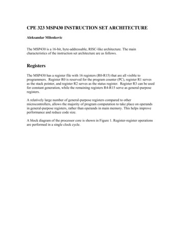
GENERAL NOTESFirst, there are a few general notes to review. Please read this section thoroughly and, REMEMBER,while the sight of all the pieces of the kit appears daunting; the construction is really very simple.The difficult carpentry has been done in the factory.To make life easier, enlist the aid of a willing assistant: a “step-and-fetch-it”; a panel holder; a toolfinder; a coffee bearer!Before starting on the dinghy,make a pair of trestles as shown inFig.1. You will find these invaluableduring building. Make up twosupports, or angled pieces, to holdthe boat steady and to prevent thehull rocking while working on it.Use the bottoms of the forward andaft transoms to mark the angles forthe supports. So the gunwales willrest on them when the hull isturned upside down, make thesupports wider than the boat.Fig. 1These items will be needed::1 pin hammer1 back saw1 set square1 drill (preferably electric)2 screwdrivers2 chisels (1/2” and 1”)1 top-cutter (wire cutting pincers)1 smoothing tool or hand plane1 pair broad-nosed pliers1 carpenters’ ruleSandpaper(coarse and fine)Drill bits: 1/16, 3/32, 1/8, 3/16 and a Countersink bit.A word about the screwdrivers — they must be a #2 (Red) and #3 (Green) Robertson (Square)screwdriver- a pair are included in your kit if you are in the USA (Robertson screws are the bestscrews in the world they are Canadian!).A Japanese style “pull saw” with a fine blade is an excellent tool to have around for close trimmingand cutting.“C” clamps are not vital to the operation but they will make life very much easier. Spring clamps areuseful too. Get about 6, 3½-inch size.In addition to the above you will require a box of inexpensive ½” brushes (for putting on the resin)and plenty of old rags for wiping the resin off tools, fingers and anything else it gets on. Latex glovesare really nice to wear when working with epoxy resins! To coat the panels (“saturate”) with epoxy, asupply of inexpensive, throw away 1” diameter by 3 “ paint rollers and throw-away trays is required.
FIXING AGENTSCAREFULLY READ AND FOLLOW THE MANUFACTURER’S INSTRUCTIONS FOR MIXING THERESINS and CATALYSTS THAT YOU ARE USING!For gluing, MSD recommends: epoxy resin with some microfibres, or cotton linters, (e.g.: Westepoxy resin 105, Hardener 205 and 403 Microfibres). Refer to the User Manual!When using resins, most cases of undue delay or failure to cure are caused by:1. Cold weather.2. High humidity.3. Insufficient catalyst.4. Mixture not thoroughly mixed together.5. Use of an old paintbrush with traces of paint left in bristles.6. Applying the resin mix over painted, damp or otherwise contaminated timber.7. Use of resin over 12 months old.8. Frost damaged resin.THE STITCH AND GLUE METHODThis is a misnomer for the actual process, which uses neither stitches nor glue!Basically, the method is to “weld” together adjacent panels with epoxy resin (not glue) to make apermanent and immensely strong joint. While the resin is setting, the panels are held edge to edgewith individual links, or “stitches”, of copper wire. The resin itself is held in place by glass fiber tape.The following is an overview of the basic procedures involved in Wiring and glassing seams A series of “stitch” holes are drilled, as instructed, along the edges of the panels to be joined. Eachhole has a counterpart in the opposite panel.A piece of copper wire about is threaded through a pair of matching holes and twisted on the outsideto form a link, like a loose leaf diary.Before the resin and tape is applied, all the twists are tightened to pull the panels together and theinside loops are flattened, or pushed, into the joint.Resin is painted along the line of the seams to the width of the tape. The tape is laid into the resinand more resin is stippled on to it.After the initial coating of the resin in the seam has “set off”, it is lightly sanded, wiped and a finalcoat of resin applied.HEALTH & SAFETYFollow the epoxy manufacturers recommendations for protection of self, others and theenvironment.Wear plastic or latex gloves, or use barrier cream when handling epoxy resins.Use respiratory protection when sanding.Have a helper to assist with moving and handling large unstable parts.
BEFORE STARTING TO BUILD – Some points to remember1. When driving in nails or pins make sure that the head of the hammer is clean.2. All nails, etc. should be driven in using a flat, firm surface as a backing - iron weight or the headof an old hammer.3. The usual practice for screwing two pieces of wood together is to drill a hole the same size asthe screw shank in the first piece of wood to be fixed and then a smaller, lead hole, in the otherpiece of wood. A screw should never have to be really forced into position. In soft wood, lead holesneed to be somewhat smaller than ones in hardwood.4. Brass screws are easily twisted and broken. For the most part, MSD includes stainless steelscrews in the kits. Put a drop of epoxy into screw holes to seal the wood.5. Do not try to glue wet, greasy or painted wood.6. When working in an out-building in frosty weather, do not let the glue or resins freeze beforesetting. This particularly applies to joints left to set overnight.7. The hotter the atmosphere, the quicker the glue and resin sets.8. Fiberglass strips must be absolutely bonded to the wood at all points with no air bubbles beneaththem. Only sand the edges of the strips - the bonded corners must be as strong as possible.(You may be using fillets on the outside (visible) seams in the cockpit – read about this in the WestSystem User Manual.)9. Sanding: Use a softwood sanding block. Sand ACROSS the grain for PAINTED surfaces, andWITH the grain for VARNISHED surfaces.10. Do not use more glue than is necessary! A thin film of glue is quite sufficient to make thestrongest joint.11. Cover the floor of the building area with paper or any covering material. Drips of epoxy will stickfirmly to most flooring materials! Provide adequate ventilation when using epoxy.12. Place plastic cling wrap between clamping blocks, weights, sawhorses, etc. and the joint whengluing or coating. (This prevents them all becoming one!)13. DON’T try to build to a thousandth of an inch - it is not necessary. Try, by all means, to achieveaccurate work but don’t get worried if there is a tiny gap between seams (the resin will fill it) or if apiece of wood doesn’t quite fit (trim it off slightly).14. DON’T listen to know-alls who are better at giving advice than building boats!15. Most parts are machined exactly to shape, and unless stated, they do not require any alterationapart from slight trimming. This particularly applies to hull panels and bulkheads. It is necessaryhowever to chamfer some edges (e.g.: deck and side panels) to obtain a closer fit.16. Memorize these points - they apply at every stage of construction. To forget any one of themmight prove a costly blunder.
If you are going to seal the wood parts (Epoxy barrier coating) do it now!Follow the manufacturer’s instructions and apply 2 coats.The third coat may be applied during construction and sealing steps.PRE CONDITIONING THE GUNWALESAlthough it will be some time before they are used, the inner and outer gunwales should be curvedroughly to shape in the following manner:Determine the way that each will be fitted in the boat.Suspend them in the roof of the garage, or support them between two boxes.Suspend a weight 48” (1.2 m) from the forward end to force them into the curve. (Note: This isnot at the mid-point. More curvature is necessary around the area of the shroud blocks,Mark where the weight was attached.When released the gunwales will resume their original shape, however, they will be less springy tohandle.
CONSTRUCTING THE HULLJOINING HULL PANELSParts 1 and 2 are joined together to produce the bottom two pieces of the hull. Parts 5 and 6 will,when joined, become the sides of the boat, and 7 and 8 are the ends (transoms).The bottom panels (1 & 2), and the side panels (5 & 6), are to be made up in matching pairs.First, it is important to establish the pairs and mark the face sides accordingly.A butt strap (2i) joins panel pairs 1 and 2.With the pieces end to end, lay the butt strap centrally over the join and mark its position on eachsection. Apply glue (epoxy with some filler) to the butt strap, to the panel edges where they meet,and to the marked area of the panels. The butt straps can be held in place temporarily with 7/8 “copper nails at the corners. Clamp the joint with clamps and cauls (long clamping blocks) or putweights (bricks) on top of the joint to apply clamping” pressure. (Don’t forget: Put some plasticbetween the bricks and the joint, and under the joint on the work surface so that they don’t all windup glued to the boat!) Allow the joint to set up and then remove or pinch off the nails.Use butt strap part 6i to join panel pairs 5 and 6 in the same way. Ensure that the butt strap is farenough away from the top edge of the panel (25 mm) to permit the inner gunwale to be fitted later.MARKING AND DRILLING HULL PANELSBefore lacing the hull together it is necessary to mark and drill the lace holes, install glue blocks, andmark the position of the stringers Place the one bottom section on top of the other, with butt straps on theinside, so that the two shapes match exactly and the cutaway portions thatwill form the centrecase slot are together. Draw a pencil line ¼” (6 mm) fromthe edge all the way round the top panel, excludingthe centrecase slot. A marking gauge is useful.Along this line, at 4” (100 mm) intervals, markpositions for lacing holes. To provide extra strengthat each corner and at the butt joints, mark two extrapoints between the 4” (100 mm) marks.NOTE: The holes closest to the centercase slotmust be at least 1 ½” (40 mm) away from the slot.Holding the panels in correct alignment, use a 3/32” (2 mm) diameter bit todrill the lacing holes through both panels at the same time.Because the holes on the side panels have to coincide exactly with those on the underside hullpanels when one curve is tensioned against the other, a slightly different technique is used to marktheir positions Place one side exactly on top of the other with the butt straps on the outside. Draw aline ¼” (6 mm) from the edge along the curved edge of the panel for only 3 FEET (900 MM) from theNARROWER END (i.e. the bow) and along the two ends of the panel. Make the drilling marks 100mm apart, as before. Along the straight edges, at the bow and the stern, the holes should be 1¼”(32 mm) apart.
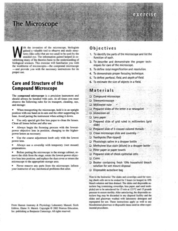
Glue Block Layout Diagram 2All dimensions are shown inmillimetres.Not to scale.Glue Block AlignmentCENTRE
The top edges of the side panels do not have holes because they do not form seams.Again, hold the panels in correct alignment and drill 3/32” (2 mm) lace holes through both.IMPORTANT: Each hole on one panel must, when the hull is assembled, be directly opposite amatching hole in the adjoining panel.The position of the glue blocks is shown in Diagram 2. Mark the bottom panels and fix the gluebocks with epoxy glue. Apply the glue to the block and to the panel position and slide the blocksaround in a circular motion to obtain a “vacuum” so that the blocks are held in position while the gluesets. Do not move the panels until the glue has set solid.NOTE: All glue blocks are beveled. The beveled side is always facing towards the centre of the boat.Marking the position of the stringers (9)Make a pencil line 5 inches (125 mm) from the top edge of the side panels (this will be a guidelinefor placing the stringer (Part 9) later).FIXING THE FLOOR BATTENS (4)It is easier to fit these battens on the bench before the boatis assembled, but a much sweeter curve of the bottompanels is achieved if the Floor Battens are fitted once thehull is completed. Either way; they are fitted with the sametechnique.Before fitting the battens, round off and fair the ends andedges (check Rule 1.6.12).Mark the position of the battens as shown. Extra battensmay be installed as noted in Rule 1.6.12. Fit them betweenthe centrecase and the footrest, on either side of the tapedcentre joint.Drill a series of holes 3/32” (2 mm) through the plywoodbottom panel in a zigzag pattern the length of each battenposition at 4” (100 mm) spacing. Do not drill holes at theextreme end or centre. Apply epoxy glue. Lay the battens intheir relative positions as shown and drill & screw (#6 x1/2”) both ends and centre of each batten, through thebatten into the plywood panel. Once this has been done,turn the panel over, drill pilot holes in the battens throughthe holes in the plywood, and fix the rest of the screwsthrough the ply into the batten. Set the screws in epoxyglue (i.e. put a drop into each screw hole and behind thehead). Ensure the screw heads are seated below thesurface of the ply.
LACING THE BOTTOM - (Joined Panels 1 & 2)Cut the copper wire in 2 ½” (65 mm) lengthsTo be able to appreciate the next steps, lay the four long panels on the floorin their respective positions with the two bottom panels together and thecutaways forming the centrecase slot and with the side panels either side ofthe bottom section. (See the inside front cover of this booklet.)Put the bottom panels together, with the buttstraps on the inside, and each pair ofcorresponding lace holes in line. Thread piecesof copper wire through the matching holes in theedge that contains the centreboard slot to linkthe panels together. Twist the ends of eachpiece of wire two or three times to give only aloose fixing. Wires will be tightened later when the hull is aligned. Tosimplify matters at a later stage, twist all wires in the same direction!Open the bottom panels out like a book to form the lower section of theboat. The two joining edges should NOT overlap but fit EXACTLY EDGETO EDGE. The two cutout portions should also coincide to form acomplete open slot.FITTING and FIXING THE AFT TRANSOM (7)NOTE: The aft transom, fits INSIDE the Hull Panels.Draw a vertical line exactly down the centre onboth sides of the aft transom (7). Use theselines to match the transom with the seam of thebottom panels. Mark off corresponding laceholes on the lower edge of the transom againstthe corresponding holes in the after edge of thebottom panel – ¼ “ (6 mm) from the edge.Match the side edges of the transom with thecorresponding after-end of each side panel andmark the lace holes. Drill the 3/32” (2 mm) laceholes in the transom.Note that the top 6 “ (150 mm) of the side panels in contact with the afttransom top are nailed and glued, not wired.Use the trestles and the support pieces to support the bottom panels. Restthe transom on the aft edge of the bottom panels and fasten with pieces ofcopper wire through the corresponding holes. It is important that the aftface of the transom is flush with the aft edge of the bottom panels.You may find it necessary to use pliers to ease the wire through the holes.
FITTING AND FIXING THE FORE TRANSOM (8)NOTE: the fore transom fits INSIDE the Hull Panels.Mark the fore transom in a similar manner to that used on the aft transom Again, draw a verticalline on both sides through the exact centre of the transom so that it can be matched to the centreline of the hull. Note that the gunwale and stem post (not shown in the pictures) face out! Also, notethat the fore tramsom riser has been fixed to the fore transom - it requires trimming at both ends.Bevel the two curved edges of the transom to make a cleaner and tidier joint between the foretransom and the bottom section. Drill the 3/32” (2 mm) lace holes.Fix one side of the fore transom to the corresponding bottompanel using the copper wire pieces to the same tension as thaton the aft transom. Note that the ends of the bottom are curved,but when they are bent around the transom the two curvescancel each other out and appear to straighten.Two people are needed forthe next stage - lacing theother curved edge of thefore transom to the otherbottom panel.While tensioning the bottom panel against the curve of the foretransom and fitting in the wire laces, the assistant tightens themon the outside by twisting. As far as possible, the fore transomshould be flush with the bottom panels.FIXING THE SIDE PANELS (5 & 6)Another two-man job: one to hold the side panel at the correctangle; one to do the lacing.When fixed, the side panels should be flush with the front ofthe fore transom and the aft of the aft transom, i.e., thetransoms fit inside topside panels.Begin at the narrow end (forward) of the panel and progress tothe stern. Lace the lower edge of the sidepiece to the bottomsection through the matching holes so that the curving edgesfit exactly (at the front, for about 12“ (300 mm), the sides buttto the outside edge of the bottom). There is a notch cut on theedges of the topside panels that allows the panels to go frombeing edge-to-edge to being outside the bottom (i.e.: forwardof the notch, the bottom and side panels butt up together; aftof the notch the side panels overlap the bottom panels). Some
beveling or trimming at the notch may necessary to make a nice fit.Only the first 36” (900 mm) of the sidepiece has been drilled for lace holes. Work along the loweredge - towards the stern - drill holes and lace with wire (one at a time) corresponding to the holes inthe bottom panel.Before lacing the last few holes near the aft transom, apply glue to the side of the transom beam andfasten the side panel to the transom beam using 7/8” copper nails or glue and clamp (requires longclamps and angled clamping blocks).Attach the other side panel in the same manner.ALIGNING THE HULLTo ensure that the hull is held in the correct shape, twoshaping cross struts (34 & 35) have been included inthe kit. Measure along the curve of the top edge of theplywood side panel 27” (686 mm) and mark. Fix theshorter strut (34), level with the top of the plywood andcentred on the marks, with screws through the plywoodinto its ends.Place the longer strut (35) in the same manner at adistance of 52½ ” (1334 mm) from the aft end of theside panel measured along the curve at the edge of thepanel.About 4” (100mm) forward of the longer cross strut fix avertical prop on either side of the boat.The props are not supplied as part of the kit. Use anylongish piece of wood (a piece of the wooden crate?). Ascrew holds each of these to the hull and the lower endrests on the floor.Aligning the hull The tops of the two transoms have to be fixed parallel and square to each other in all threedimensions!To see if the line of the top edge of the fore transom is parallel to the corresponding top edge of theaft transom, look along the length of the hull just over the aft transom. Adjust the props until thetransoms line up and any twist in the hull is remedied. Alternatively, two pieces of thread, or lightstring, can b
mind that the original concept of the Mirror Dinghy was, and still is, a tough little dinghy that is both versatile and a pleasure to sail. To construct a Mirror as a high performance racing dinghy requires extensive knowledge and building