Transcription
SCIENCE CHINAInformation Sciences. REVIEW .Special Focus on Advanced Microelectronics TechnologyJune 2016, Vol. 59 061406:1–061406:23doi: 10.1007/s11432-016-5560-6Design for manufacturability and reliabilityin extreme-scaling VLSIBei YU1,2 , Xiaoqing XU2 , Subhendu ROY2,3 , Yibo LIN2 ,Jiaojiao OU2 & David Z. PAN2 *1CSEDepartment, The Chinese University of Hong Kong, NT Hong Kong, China;Department, University of Texas at Austin, Austin, TX 78712, USA;3Cadence Design Systems, Inc., San Jose, CA 95134, USA2ECEReceived December 14, 2015; accepted January 18, 2016; published online May 6, 2016Abstract In the last five decades, the number of transistors on a chip has increased exponentially in accordancewith the Moore’s law, and the semiconductor industry has followed this law as long-term planning and targetingfor research and development. However, as the transistor feature size is further shrunk to sub-14nm nanometerregime, modern integrated circuit (IC) designs are challenged by exacerbated manufacturability and reliabilityissues. To overcome these grand challenges, full-chip modeling and physical design tools are imperative toachieve high manufacturability and reliability. In this paper, we will discuss some key process technology andVLSI design co-optimization issues in nanometer VLSI.Keywordsdesign for manufacturability, design for reliability, VLSI CADCitationYu B, Xu X Q, Roy S, et al. Design for manufacturability and reliability in extreme-scaling VLSI. SciChina Inf Sci, 2016, 59(6): 061406, doi: 10.1007/s11432-016-5560-61IntroductionMoore’s law, which is named after Intel co-founder Gordon Moore, predicts that the density of transistoron integrated circuits (ICs) roughly doubles every two years. In the last five decades, the transistornumber on a chip has increased exponentially in accordance with the Moore’s law. The semiconductorindustry has followed this law for guiding research and development [1]. However, as the transistor featuresize is further shrunk into extreme scaling (e.g., 10 nm and beyond), the industry is facing tremendouschallenges in achieving high manufacturability and reliability.The first key challenge comes from lithography limits and manufacturability. For a long time, theoptical lithography has been utilized as the main driving force in shrinking transistor/interconnect featuresize. However, the continued scaling of the minimum feature size has pushed the 193 nm wavelengthlithography to its resolution limit, and the gap between the manufacturing capability and the designexpectation becomes more and more critical. Therefore, new advanced lithography techniques have to beused to enable further pitch scaling beyond the single exposure with 193 nm wavelength lithography [2,3].* Corresponding author (email: dpan@ece.utexas.edu)c Science China Press and Springer-Verlag Berlin Heidelberg 2016 info.scichina.comlink.springer.com
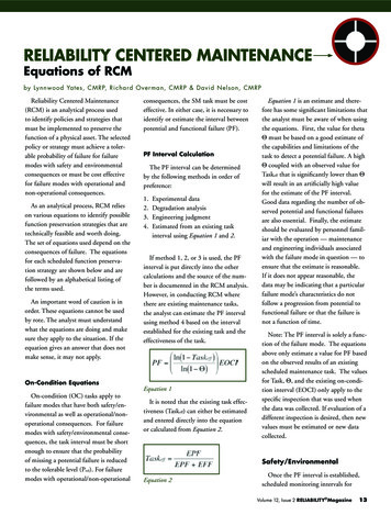
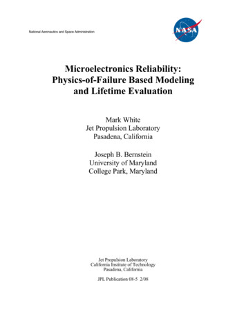
Yu B, et al.Sci China Inf SciJune 2016 Vol. 59 061406:2EUV193i DPLCourtesy y EtchQuadruple patterningBCPAnnealPatterntransferCourtesy Intel(a)Courtesy MAPPER(b)(c)Figure 1 (Color online) Advanced lithography techniques. (a) Double patterning and quadruple patterning with 193 nmwavelength lithography; (b) extreme ultra violet (EUV) and electron beam lithography (EBL); (c) directed self-assembly(DSA) with pattern transfer.In the near term, multiple patterning lithography (MPL) has become the most viable lithography technique. As illustrated in Figure 1(a), MPL splits target patterns into several masks so that the coarserpitches on each mask can be single patterned using the 193 nm wavelength lithography. Then patternson different masks are combined to obtain finer pitches. According to different processes, MPL can beclassified into LELE-type MPL and spacer-type MPL. LELE-type MPL includes double patterning lithography (DPL), triple patterning lithography (TPL) and quadruple patterning lithography (QPL), whilespacer-type MPL includes self-aligned double patterning (SADP) and self-aligned quadruple patterning(SAQP). For the LELE-type MPL, it introduces complex coloring/stitching constraints and the overlayamong multiple masks needs to be optimized to reduce the timing impact. For the spacer-type MPL,it provides better overlay control but prefers regular layout patterns due to more complicated coloringconstraints. In particular, LELE-type DPL has been widely adopted in industry for 20/14 nm technologynodes. LELE-type TPL/QPL and spacer-type SADP/SAQP are promising and competitive candidatesfor 10 nm node and beyond due to the delay of other emerging lithography techniques.In the longer term, next-generation emerging lithography technologies, including extreme ultra violet(EUV) lithography, electron beam lithography (EBL), and directed self-assembly (DSA), are under intensive research and development. EUV has very short wavelength (13.5 nm) to provide finer printingresolution compared to the 193 nm wavelength lithography as shown in Figure 1(b). However, tremendouschallenges, such as power sources, resists and defect-free masks, have notably delayed the adoption of EUVfor volume production. EBL directly uses the charged particle beam to pattern target layout features,as shown in Figure 1(b). As a maskless technology, EBL avoids the light diffraction from the mask, thushas been widely used in mask manufacturing and low-volume test chips. However, its throughput is stilltoo low for electron beam direct-write on wafer for IC volume production. DSA enables sub-lithographicprinting as shown in Figure 1(c). The guiding templates are first printed using the 193 nm wavelengthlithography, and then they are filled with special chemical material such as block copolymer. After theannealing process, cylinders will be formed and transfered to substrate patterns with sub-lithographicpitches.Another key nanometer IC challenge comes from reliability, which usually refers to how robust a chip isafter manufacturing. The reliability issue profoundly impacts all aspects of circuits performance and maycause significant deviations from the prescribed specifications of a chip [4]. It can be soft error, or harderror due to aging, such as bias temperature instability (BTI), electromigration (EM), and so on. Withcontinued feature size shrinking and increased transistor density, reliability issue is more and more severe.
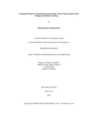
Yu B, et al.Sci China Inf SciDFMStandard cell designLogic synthesisPlacementJune 2016 Vol. 59 061406:3Automatic cell synthesisPin access optimizationDensity optimization for CMPLithograph aware placement & routingLithograph friendly mask optimizationPG designDFRClock synthesisRoutingMask optimizationFigure 2NBTI modelingNBTI aware gate sizingEM modeling for interconnectionEM aware standard cell designEM aware wire sizingSoft errors(Color online) Physical design flow and challenges for both DFM and DFR.That is, reliable circuit operations cannot be guaranteed over the expected product lifetime. In addition,new materials and novel device architectures (e.g., FinFET) introduce new reliability threats [5].To overcome these issues, full-chip modeling and CAD tools are imperative to achieve high printabilityand high reliability. Figure 2 shows a typical physical design flow, with related manufacturability andreliability concerns. On one hand, the advanced patterning techniques aforementioned impose additionalphysical design constraints, and call for new design-for-manufacturability (DFM) schemes across differentdesign stages. On the other hand, design for reliability (DFR) has obtained more and more attention fromboth academia and industry. The conventional reliability aware design may force designers to use largedesign margins, which may limit circuit performance, and yet the circuit lifetime uncertainty still remains.How to model the variation or uncertainty, as well as how to intelligently balance circuit performanceand reliability is key in DFR process.In this paper, we will survey recent developments in design for manufacturability and reliability inextreme-scaling VLSI, including challenges, solutions, results, and future research directions. The rest ofthis paper is organized as follows. In Section 2 we will discuss the design for manufacturability issues.In Section 3 we will cover the design for reliability issues, followed by conclusion and future directions inSection 4.2Design for manufacturability (DFM)In emerging technology nodes, manufacturability becomes a more and more severe issue, even with variousresolution enhancement techniques, e.g., optical proximity correction (OPC), phase shift mask (PSM),and sub-resolution assist feature (SRAF) insertion. To overcome the manufacturing problem and improvecircuit yield, several early design stages should be aware of the manufacturing constraints. In this section,we discuss how manufacturability can be seamlessly considered in four physical and mask design stages:standard cell design, placement, routing, and mask optimization.2.1DFM in standard cell designAs the foundation for the back-end design flow, the standard cell library design plays an importantrole in the physical design closure. Due to the ever-increasing DFM challenges in advanced technologynodes, standard cell designers spend huge amount of efforts to achieve manufacturing friendliness [6–8]. The complex DFM constraints introduce undesirable interactions across neighboring standard cellsduring the placement and routing stages. This means that designers not only need to improve themanufacturability for each individual standard cell, but also need to consider the lithographic interactionsacross cell boundaries when cells are placed next to each other. Therefore, standard cell design andevaluation considering DFM constraints are critical to obtain a robust cell library that can be used inany design implementation.
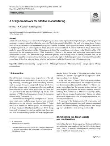
Yu B, et al.Sci China Inf SciJune 2016 Vol. 59 061406:4PolyLayoutMetal-11st mask2nd maskMetal-23rd maskCA4th maskSC boundaryCB(a)(b)Figure 3 (Color online) (a) An standard cell with regular layout patterns; (b) 3-cell interactions under MPL-specificconstraints.For an individual standard cell design, regular layout styles have been extensively used across various layers, such as the middle-of-line (MOL) layers, to obtain lithography-friendly layout. An examplefor regular layout patterns is shown in Figure 3(a), where layout patterns for intra-cell connectionsare unidirectional. Although manual standard cell designs are still widely used to get the best performance/area/power, etc. [7, 8], automatic standard cell synthesis has been actively studied to achievecomparable design quality and shorter turnaround time [9–15]. Taylor et al. [9] and Maly et al. [10] haveearly studies on applying regular layout patterns in standard cell synthesis. Considering the simplicity and discreteness of regular layout patterns, various combinatorial optimization techniques have beenproposed for standard cell synthesis while accommodating complex DFM constraints. Taylor et al. [9]and Wu et al. [13] introduce the branch and bound method with smart pruning techniques for the celllayout generation. For the regular layout towards 1-D gridded design, line-gap distributions are explicitly optimized in [11, 13] to improve the manufacturing yield. Ryzhenko et al. [12] propose the booleansatisfiability (SAT) formulation for the cell layout generation. Hougardy et al. [14] and Ye et al. [15]further propose the integer linear programming (ILP) method for the cell layout synthesis with consideration of practical DFM constraints. During library design phase, designers aim at a robust standardcell library that is applicable in any design implementation. In advanced technology nodes, MPL-specificviolations may be introduced across multiple cell instances placed next to each other, which makes therobust standard cell library design ever-challenging [16]. Figure 3(b) illustrates the 3-cell interaction introduced by the MPL coloring constraints. Quadruple patterning, i.e., 4 colors, is needed to achieve colorassignment for the layout patterns in the circle window. However, if triple patterning is used, it becomesan illegal cell combination due to the TPL conflict. A robust standard cell library should minimize thenumber of illegal cells or combinations of cells. Xu et al. [16] propose the first framework for the libraryrobustness evaluation over MPL-specific constraints. During library design stage, a compact set of illegalcells or combinations of cells are quickly computed so that designers can improve the associated layoutincrementally.Moreover, due to the continued density and area scaling, limited number of routing tracks are availablefor the standard cell design. The Input/Output (I/O) pin access becomes more and more difficult becauseeach I/O pin has limited number of access points and they interfere with each other under restrictiveMPL constraints. Xu et al. [17] introduces the pin access optimization (PAO) technique considering theMPL-specific constraints for the metal and via layers. As shown in Figure 4, the line-end extensionsbeyond the via positions are necessary to achieve SADP-friendly Metal-2 wires for pin access. The pinaccess and cell layout co-optimization is further proposed to maximize the pin access flexibility for therouting stage.2.2DFM in placementTraditional placement problem for physical design has been studied for almost half a century and plentyof useful techniques have been proposed to improve the placement engines. However, due to the rapid
Yu B, et al.(a)Sci China Inf SciJune 2016 Vol. 59 061406:5(b)Figure 4 (Color online) PAO for one pin access candidate. (a) SADP design rule violations in the dashed rectangles; (b)optimized Metal-2 wires with line-end extensions for pin access [17].development of technology node along with more and more complicated design rules, consideration ofmanufacturing effects in early design stage has become a necessity. Researches on manufacture awareplacement follow the advancement of manufacturing process and try to resolve challenges for specificprocess technology.Manufacturing objectives are typically formulated into cell abutting cost or constraints; i.e., there willbe additional cost if two specific types of cells are placed next to each other. Due to the existence of widehorizontal power grid in row based structure, standard cells can be regarded as vertically isolated, butcells can be very close to each other in horizontal direction. Therefore, horizontal abutting often requiresmore attention during placement for lithography awareness.Hu et al. [18] propose incremental placement algorithms to honor refractive effects in lithography for45 nm technology. The lithography effects are formulated into abutting cost for each cell pair. Cellflipping and local movement are introduced to minimize total cost along each placement row. Chenet al. [19] propose the first metal-density-driven placement engine to reduce variation during chemicalmechanical polishing (CMP). They integrate a predictive CMP model into the placement algorithm andoptimize metal density globally. Besides deterministic approaches, Shim et al. [20] study the property ofinner-cell margin and came up with a new placement problem with defect probability minimization as theobjective. It is argued in their paper that inner-cell margin is not always necessary to avoid lithographydefect. They propose probability based approach along with simulated annealing algorithm to reducedefect probabilities.With the increasing popularity of multiple patterning lithography (MPL), the placement problemrelated to MPL has also been studied deeply, including double patterning lithography (DPL) [21–23],self-aligned double patterning (SADP) [24], and triple patterning lithography (TPL) [25–30]. To achieveDPL friendly layout, Gupta et al. [21] study the timing model for cell layouts under DPL and a dynamicprogramming based algorithm is proposed to solve coloring conflicts. To further improve DPL friendliness,a new DPL design flow is proposed including cell-level design, DPL aware placement, and DPL awarerouting [22]. The coloring problems are considered during placement, routing and post-routing stagesso that better manufacturability is achieved. Gao et al. [24] solve decomposition conflicts for SADP atplacement stage with cell flipping and spreading.In TPL placement, the major lithography objective is to avoid coloring conflicts while minimizingnumber of stitches. The conflicts come from identical color assignment to vias or metal-1 wire segmentsat the boundary of cells. However, the color assignments remain undetermined in conventional physicaldesign flow where layout decomposition is performed after placement and routing. Therefore, in theTPL friendly flow proposed by Yu et al. [31], standard cells are pre-colored with candidate coloringsolutions and a look-up table (LUT) is constructed to store all the candidates. Although there might belarge amount of coloring solutions for even a single cell, the number of pre-coloring solutions is limiteddue to the observation that only wire segments near cell boundary matter. Only color assignments forboundary segments need to be enumerated, which reduces the solution space to a large extent. Figure 5shows an example of conflict between two abutting cells with specific coloring solutions, either insertingsome whitespace between two cells or switching the coloring solutions will resolve the conflict. Hence,the placement problem consists of two parts: optimizing wirelength as the conventional objective, andavoiding conflicts and minimizing stitches as the lithography objective by determining the locations andcoloring solutions of cells. Several graph based algorithms are proposed to determine cell locations and
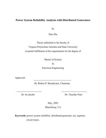
Yu B, et al.Sci China Inf Sci(a)June 2016 Vol. 59 061406:6(b)(c)Figure 5 (Color online) (a) An example of TPL conflict; (b) conflict removal by whitespace insertion; (c) conflict removalby switching coloring acer-2StageTPLPlacer-MDP#STWL 1(b)70pto0l-7ct70cef 07cec70vdi 70pby70ual0.170pto0l-7ct70cef 07cec 07vdi 70pby70ual70pto0l-7ct70cef 07cec70vdi 70pby70ual(a)100Seconds6(c)Figure 6 (Color online) Experimental results of different algorithms in TPL placer from Yu et al. [28] on benchmarkswith 70% utilization. (a) Wirelength improvement, (b) number of stitches, and (c) runtime.coloring solutions simultaneously for each placement row. Kuang et al. [26] further extend Yu’s flowby predetermining coloring solution for each standard cell and try avoiding conflicts only by placementtechniques. Chien et al. [29] also propose different approaches to solve detailed placement and celldecomposition problems.Tian et al. [25] and Lin et al. [27] argue that cells of the same type should have the same colorassignment for better timing variation. This additional constraint results in the NP-completeness of theproblem even for ordered single row version [27]. With further shrinking of feature sizes, middle-of-line(MOL) layers are introduced for local interconnection, which is possible to cause cross-row conflicts. Linet al. [30] study the layout patterns of MOL layer and show that it is more feasible to avoid four-wayclique (K4) structure than pre-coloring MOL layer. They develop a framework to handle conflicts in bothMetal-1 and MOL layers simultaneously.Besides general lithography and MPL aware placement, there are some other researches focusing onemerging technology, like electron beam lithography (EBL), extreme ultra violet (EUV), and DirectedSelf-Assembly (DSA) [32–35]. For example, in EBL, due to the application of multiple electron beamlithography (MEBL) for throughput improvement, the features at boundaries of beams are susceptible tostitch errors. Therefore, it is necessary to avoid features near such regions for better manufacturability,which needs to be considered during both placement [32] and routing [36]. For this problem, Lin et al. [32]propose a linear time dynamic programming algorithm for simultaneous optimization on wirelength andstitch errors.Figure 6 shows the performance of three algorithms in the TPL aware placer proposed by Yu etal. [28]. “TPLPlacer” denotes the algorithm that is able to determine cell coloring solutions and positionssimultaneously with a graph model. Each cell is allowed to shift to any placement site in a row withgiven order of the cell sequence. The drawback for this algorithm lies in the runtime overhead fromlarge graph size. The runtime complexity is related to product of number of cells, total number ofplacement sites, and amount of candidate coloring solutions for each cell. The number of placement sitesin each row can be quite large, resulting in expensive computational efforts, as shown in Figure 6(c).
Yu B, et al.Sci China Inf SciJune 2016 Vol. 59 061406:7“TPLPlacer-2Stage” divides the previous strategy into two stages to overcome the speed overhead.That is, the coloring solutions are first determined; then in the second stage, cells are shifted to avoidcoloring conflicts. Although it is necessary to solve graph models in both stages, these graphs turnout to be much smaller and easier to solve. The benefits in runtime can be seen in Figure 6(c), whilethe solution quality degrades in terms of stitch numbers, shown as Figure 6(b). The third algorithm,“TPLPlacer-MDP”, tries to trade-off quality and runtime in another perspective by limiting the rangeof movement for each cell. Instead of allowing cells to be placed in any positions, it constrains cells insuch a way that they can only be shifted to their neighboring sites. A dynamic programming algorithmis proposed to solve the constrained problem. Figure 6 (a) and (b) show that it can achieve almost thesame solution quality as that of “TPLPlacer”, while the runtime is reduced dramatically.2.3DFM in routingIn 14 nm technology node and beyond, MPL is needed for routing patterns with tight pitches on lowermetal layers, such as Metal-2 and Metal-3. Novel routing strategies are crucial to obtain legal routingresults while accommodating MPL-specific constraints. LELE, i.e., double patterning (DP), aware detailed routing is first studied by Cho et al. [37] with a grid-based approach, where colors of grids areassigned during the routing stage to obtain LELE-friendly routing patterns. Yuan et al. [38] furtherincorporate redundant-via considerations during DP aware routing with an integer linear programming(ILP) formulation. Lin et al. [39] propose the innovative conflict graph to enable efficient DP conflictdetection and removal along with the sequential routing. Lin et al. [40] further introduce the comprehensive conflict graph to obtain a novel gridless routing scheme considering DP, optical proximity correctionand balanced mask density simultaneously. Moreover, for the MP aware routing with more than twoLE steps, such as TPL, the coloring conflict detection and removal will be much more sophisticated dueto the difficulties from the color assignment and overlay control. Different from methodologies basedon the conflict detection and removal, Ma et al. [41] propose a routing grid model with expanded gridsto deal with the TPL constraints systematically. Due to high complexity of color assignment for TPL,Lin et al. [42] propose a token graph-embedded conflict graph to enable the TPL conflict detection andachieve TPL-friendly routing patterns in a correct-by-construction manner. A conflict pre-coloring basedapproach is proposed in [43] to avoid stitches in the routing patterns and improve the manufacturingyield. Liu et al. [44] argue that an iterative ripup and reroute approach can achieve TPL-friendly routingpatterns with better solution qualities.In future technology nodes, regular routing patterns towards 1-D gridded design are preferred dueto better manufacturability and simplified coloring schemes [45]. The spacer-type MPL is potentiallyattractive for lower metal routing layers due to its better control on overlay and line edge roughness.Mirsaeedi et al. [46] present the first study on the self-aligned double patterning (SADP) aware routingwith the grid-based approach. Gao et al. [47] propose prescribed layout planning schemes to obtain SADPfriendly routing patterns with better solution qualities. Kodama et al. [48] introduce simple connectingand cutting rules during grid color assignment to achieve SADP/SAQP-friendly routing results. Insteadof assigning colors to grids, Du et al. [49] propose an expanded routing grid model to deal with theSADP-specific constraints, where a negotiation congestion-based routing scheme is adopted during therouting stage. Liu et al. [50] further demonstrate an overlay constrained graph to guide the router andachieved better solution qualities. Fang et al. [51] introduce a novel wire planning scheme to enablefull-chip routing with cut mask optimization for general self-aligned multiple patterning. While most ofthe spacer-type MPL aware routers focus on the spacer which is dielectric type of manufacturing scheme,Ding et al. [52] introduce a color pre-assignment and an expanded graph model to deal with the spacerwhich is metal type of manufacturing scheme.Furthermore, MPL-specific constraints have introduced complex neighboring interactions among routing patterns. The local standard cell pin access is becoming extremely difficult since the router needs toaccess congested I/O pins within limited number of access points while accommodating complex neighboring interactions. To improve the standard cell pin accessibility, Xu et al. [53] propose pin access
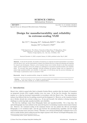
120DAC'14 [50]LPAPLPAP RNRLPAP GPAPLPAP GPAP RNR110Routability (%)Sci China Inf Sci100908070June 2016 Vol. 59 061406:86 105DAC'14 [50]LPAPLPAP RNRLPAP GPAPLPAP GPAP RNR5Wirelength*Yu B, et h(b)divtopFigure 7 (Color online) SADP-friendly detailed routing with pin access planning schemes for various OpenSPARC benchmarks. Specific pin access planning schemes include local pin access planning (LPAP), global pin access planning (GPAP)and pin access driven rip-up and reroute (RNR).planning strategies, including local pin access planning (LPAP), global pin access planning (GPAP)and pin access driven rip-up and reroute (RNR) to enable the handshake between library-level pin access and the detailed routing stage, which obtains SADP-friendly routing patterns and better solutionqualities compared with a state-of-the-art SADP-aware detailed router [50]. Figure 7 demonstrates thecomprehensive comparisons among various routing strategies, including the detailed router [50], “LPAP”,“LPAP RNR”, “LPAP GPAP” and “LPAP GPAP RNR”. The solution qualities are measured by “Routability” and “Wirelength*” in Figure 7 (a) and (b), respectively. “Routability” is defined as the number ofrouted nets over the total number of nets in the design. It is difficult to achieve 100% routability owing tothe problem complexity. For the benchmark “top”, the results of DAC’14 [50] are not shown in Figure 7(a) and (b) because the routing cannot be finished within affordable amount of runtime. “Wirelength*” isdefined as the summation of routed wirelength of routed nets and half-perimeter wirelength of un-routednets. Figure 7(a) demonstrates that the scheme of “LPAP GPAP RNR” achieves the highest routabilitycompared to other schemes, including a 10% routability improvement on average over [50]. Figure 7(b)illustrates comparable “wirelength*” among different strategies. It shall be noted that, since the schemeof “LPAP GPAP RNR” obtains highest routability, we expect the “wirelength*” metrics of other schemeswill increase significantly if similar routability could be achieved. Therefore, the proposed pin access planning schemes are critical to obtain high-quality routing solutions while satisfying complex SADP-relatedconstraints in advanced technology nodes.2.4Mask optimization2.4.1 MPL layout decompositionOne of the biggest challenges in multiple patterning lithography (MPL) is the mask assignment problem.Since each mask is manufactured by 193 nm optical source, there is a requirement on the distance betweenany two patterns belonging to the same mask. If any two patterns in a mask fail to meet the requirement,they are not able to be printed well and thus result in a conflict. The process of splitting layout intoseveral masks is called layout decomposition. The requirement for layout decomposition varies fromdifferent lithograph techniques, but the major objective is to avoid conflicts.LELE-type MPL decomposition is typically formulated into graph coloring problem, as mask assignment is very similar to vertex labeling; e.g., DPL layout decomposition corresponds to 2-coloring andTPL layout decomposition corresponds to 3-coloring. However, layout decomposition is still differentfrom traditional graph coloring problem due to the existence of stitches; i.e., a wire segment can be splitinto multiple parts and assigned to separate masks to resolve conflicts. Even though stitches are able toremove conflicts, they should not be abused for the reason of overlay and misalignment issues [54]. Therefore, the typical objective in LELE-type MPL decomposition is to minimize both conflicts and stitcheswith higher weights of conflicts over stitches. Figure 8 shows an exmaple of DPL layout decomposition.
Yu B, et al.Sci China Inf SciJune 2016 Vol. 59 061406:91221112(a)Figure 8insertion.(b)(Color online) An example of (a) DPL layout decomposition with conflict and (b) conflict removal by stitchWithout stitch insertion, there would be a coloring conflict shown by the red edge of Figure 8(a), but itis resolved by splitting the wire segment, shown as Figure 8(b).For DPL layout decomposition, Anton et al. [55] study its feasibility from process windows’ perspective. While it is true that 2-coloring can be s
physical design constraints, and call for new design-for-manufacturability (DFM) schemes across different design stages. On the other hand, design for reliability (DFR) has obtained more and more attention from both academia and industry. The conventional