Transcription
PDHonline Course G253 (4 PDH)Engineering Symbology, Prints and DrawingsInstructor: A. Bhatia, B.E.2012PDH Online PDH Center5272 Meadow Estates DriveFairfax, VA 22030-6658Phone & Fax: 703-988-0088www.PDHonline.orgwww.PDHcenter.comAn Approved Continuing Education Provider
DOE-HDBK-1016/1-93JANUARY 1993DOE FUNDAMENTALS HANDBOOKENGINEERING SYMBOLOGY,PRINTS, AND DRAWINGSVolume 1 of 2U.S. Department of EnergyWashington, D.C. 20585FSC-6910DISTRIBUTION STATEMENT A. Approved for public release; distribution is unlimited.
Department of EnergyFundamentals HandbookENGINEERING SYMBOLOGY, PRINTS,AND DRAWINGSModule 1Introduction to Print Reading
Introduction To Print ReadingDOE-HDBK-1016/1-93TABLE OF CONTENTSTABLE OF CONTENTSLIST OF FIGURES . . . . . . . . . . . . . . . . . . . . . . . . . . . . . . . . . . . . . . . . . . . . . . . . . . iiLIST OF TABLES . . . . . . . . . . . . . . . . . . . . . . . . . . . . . . . . . . . . . . . . . . . . . . . . . . . iiiREFERENCES . . . . . . . . . . . . . . . . . . . . . . . . . . . . . . . . . . . . . . . . . . . . . . . . . . . .ivOBJECTIVES . . . . . . . . . . . . . . . . . . . . . . . . . . . . . . . . . . . . . . . . . . . . . . . . . . . . .vINTRODUCTION TO PRINT READING . . . . . . . . . . . . . . . . . . . . . . . . . . . . . . . . .1Introduction . . . . . . .Anatomy of a DrawingThe Title Block . . . . .Grid System . . . . . . .Revision Block . . . . .Changes . . . . . . . . . .Notes and Legend . . .Summary . . . . . . . . .12256789INTRODUCTION TO THE TYPES OF DRAWINGS,VIEWS, AND PERSPECTIVES . . . . . . . . . . . . . . . . . . . . . . . . . . . . . . . . . . . . . . . . 10Categories of Drawings . . . . . . . . . . . . . . . . . . . . .Piping and Instrument Drawings (P&IDs) . . . . . . . . .Electrical Single Lines and Schematics . . . . . . . . . . .Electronic Diagrams and Schematics . . . . . . . . . . . .Logic Diagrams and Prints . . . . . . . . . . . . . . . . . . .Fabrication, Construction, and Architectural DrawingsDrawing Format . . . . . . . . . . . . . . . . . . . . . . . . . .Views and Perspectives . . . . . . . . . . . . . . . . . . . . .Summary . . . . . . . . . . . . . . . . . . . . . . . . . . . . . . .Rev. 0Page i.101011131414161922PR-01
LIST OF FIGURESDOE-HDBK-1016/1-93Introduction To Print ReadingLIST OF FIGURESFigure 1 Title Block . . . . . . . . . . . . . . . . . . . . . . . . . . . . . . . . . . . . . . . . . . . . . . . . . 3Figure 2 Example of a Grid . . . . . . . . . . . . . . . . . . . . . . . . . . . . . . . . . . . . . . . . . . . . 5Figure 3 Revision Block . . . . . . . . . . . . . . . . . . . . . . . . . . . . . . . . . . . . . . . . . . . . . . 6Figure 4 Methods of Denoting Changes . . . . . . . . . . . . . . . . . . . . . . . . . . . . . . . . . . . . 7Figure 5 Notes and Legends . . . . . . . . . . . . . . . . . . . . . . . . . . . . . . . . . . . . . . . . . . . 8Figure 6 Example P&ID . . . . . . . . . . . . . . . . . . . . . . . . . . . . . . . . . . . . . . . . . . . . . 10Figure 7 Example of a Single Line . . . . . . . . . . . . . . . . . . . . . . . . . . . . . . . . . . . . . . 11Figure 8 Example of a Schematic . . . . . . . . . . . . . . . . . . . . . . . . . . . . . . . . . . . . . . . 12Figure 9 Example of an Electronic Diagram . . . . . . . . . . . . . . . . . . . . . . . . . . . . . . . 13Figure 10 Example of a Logic Print . . . . . . . . . . . . . . . . . . . . . . . . . . . . . . . . . . . . . 14Figure 11 Example of a Fabrication Drawing . . . . . . . . . . . . . . . . . . . . . . . . . . . . . . . 15Figure 12 Example of a Single Line P&ID . . . . . . . . . . . . . . . . . . . . . . . . . . . . . . . . 16Figure 13 Example Pictorial . . . . . . . . . . . . . . . . . . . . . . . . . . . . . . . . . . . . . . . . . . . 17Figure 14 Example of an Assembly Drawing . . . . . . . . . . . . . . . . . . . . . . . . . . . . . . . 17Figure 15 Example of a Cutaway . . . . . . . . . . . . . . . . . . . . . . . . . . . . . . . . . . . . . . . 18Figure 16 Example Orthographic Projection . . . . . . . . . . . . . . . . . . . . . . . . . . . . . . . . 19Figure 17 Orthographic Projections . . . . . . . . . . . . . . . . . . . . . . . . . . . . . . . . . . . . . . 20Figure 18 Example of an Isometric . . . . . . . . . . . . . . . . . . . . . . . . . . . . . . . . . . . . . . 21PR-01Page iiRev. 0
Introduction To Print ReadingDOE-HDBK-1016/1-93INTRODUCTION TO PRINT READINGINTRODUCTION T O PRINT READINGA through knowledge of the information presented in the title block, the revisionblock, the notes and legend, and the drawing grid is necessary before a drawingcan be read. This information is displayed in the areas surrounding the graphicportion of the drawing.EO 1.1STATE the five types of information provided in the title blockof an engineering drawing.EO 1.2STATE how the grid system on an engineering drawing is usedto locate a piece of equipment.EO 1.3STATE the three types of information provided in the revisionblock of an engineering drawing.EO 1.4STATE the purpose of the notes and legend section of anengineering drawing .IntroductionThe ability to read and understand information contained on drawings is essential to perform mostengineering-related jobs. Engineering drawings are the industry's means of communicatingdetailed and accurate information on how to fabricate, assemble, troubleshoot, repair, and operatea piece of equipment or a system. To understand how to "read" a drawing it is necessary to befamiliar with the standard conventions, rules, and basic symbols used on the various types ofdrawings. But before learning how to read the actual "drawing," an understanding of theinformation contained in the various non-drawing areas of a print is also necessary. This chapterwill address the information most commonly seen in the non-drawing areas of a nuclear gradeengineering type drawing. Because of the extreme variation in format, location of information,and types of information presented on drawings from vendor to vendor and site to site, alldrawings will not necessarily contain the following information or format, but will usually besimilar in nature.In this handbook the terms print, drawing, and diagram are used interchangeably to denote thecomplete drawing. This includes the graphic portion, the title block, the grid system, the revisionblock, and the notes and legend. When the words print, drawing, or diagram, appear in quotes,the word is referring only to the actual graphic portion of the drawing.Rev. 0Page 1PR-01
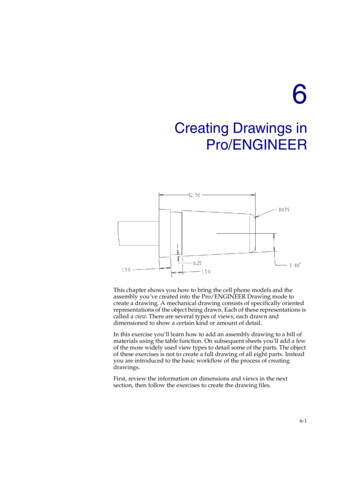
INTRODUCTION TO PRINT READINGDOE-HDBK-1016/1-93Introduction To Print ReadingAnatomy of a DrawingA generic engineering drawing can be divided into the following five major areas or parts.1.2.3.4.5.Title blockGrid systemRevision blockNotes and legendsEngineering drawing (graphic portion)The information contained in the drawing itself will be covered in subsequent modules. Thismodule will cover the non-drawing portions of a print. The first four parts listed above provideimportant information about the actual drawing. The ability to understand the informationcontained in these areas is as important as being able to read the drawing itself. Failure tounderstand these areas can result in improper use or the misinterpretation of the drawing.The Title BlockThe title block of a drawing, usually located on the bottom or lower right hand corner, containsall the information necessary to identify the drawing and to verify its validity. A title block isdivided into several areas as illustrated by Figure 1.First Area of the Title BlockThe first area of the title block contains the drawing title, the drawing number, and liststhe location, the site, or the vendor. The drawing title and the drawing number are usedfor identification and filing purposes. Usually the number is unique to the drawing andis comprised of a code that contains information about the drawing such as the site,system, and type of drawing. The drawing number may also contain information such asthe sheet number, if the drawing is part of a series, or it may contain the revision level.Drawings are usually filed by their drawing number because the drawing title may becommon to several prints or series of prints.Second Area of the Title BlockThe second area of the title block contains the signatures and approval dates, whichprovide information as to when and by whom the component/system was designed andwhen and by whom the drawing was drafted and verified for final approval. Thisinformation can be invaluable in locating further data on the system/component design oroperation. These names can also help in the resolution of a discrepancy between thedrawing and another source of information.PR-01Page 2Rev. 0
Introduction To Print ReadingDOE-HDBK-1016/1-93INTRODUCTION TO PRINT READINGFigure 1 Title BlockThird Area of the Title BlockThe third area of the title block is the reference block. The reference block lists otherdrawings that are related to the system/component, or it can list all the other drawings thatare cross-referenced on the drawing, depending on the site's or vendor's conventions. Thereference block can be extremely helpful in tracing down additional information on thesystem or component.Other information may also be contained in the title block and will vary from site to site andvendor to vendor. Some examples are contract numbers and drawing scale.Rev. 0Page 3PR-01
INTRODUCTION TO PRINT READINGDOE-HDBK-1016/1-93Introduction To Print ReadingDrawing ScaleAll drawings can be classified as either drawings with scale or those not drawn to scale.Drawings without a scale usually are intended to present only functional information aboutthe component or system. Prints drawn to scale allow the figures to be renderedaccurately and precisely. Scale drawings also allow components and systems that are toolarge to be drawn full size to be drawn in a more convenient and easy to read size. Theopposite is also true. A very small component can be scaled up, or enlarged, so that itsdetails can be seen when drawn on paper.Scale drawings usually present the information used to fabricate or construct a componentor system. If a drawing is drawn to scale, it can be used to obtain information such asphysical dimensions, tolerances, and materials that allows the fabrication or constructionof the component or system. Every dimension of a component or system does not haveto be stated in writing on the drawing because the user can actually measure the distance(e.g., the length of a part) from the drawing and divide or multiply by the stated scale toobtain the correct measurements.The scale of a drawing is usually presented as a ratio and is read as illustrated in thefollowing examples.PR-011" 1"Read as 1 inch (on the drawing) equals 1 inch (on the actualcomponent or system). This can also be stated as FULL SIZE inthe scale block of the drawing. The measured distance on thedrawing is the actual distance or size of the component.3/8" 1'Read as 3/8 inch (on the drawing) equals 1 foot (on the actualcomponent or system). This is called 3/8 scale. For example, if acomponent part measures 6/8 inch on the drawing, the actualcomponent measures 2 feet.1/2" 1'Read as 1/2 inch (on the drawing) equals 1 foot (on the actualcomponent or system). This is called 1/2 scale. For example, if acomponent part measures 1-1/2 inches on the drawing the actualcomponent measures 3 feet.Page 4Rev. 0
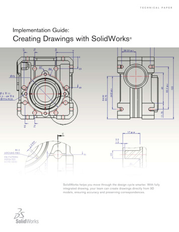
Introduction To Print ReadingDOE-HDBK-1016/1-93INTRODUCTION TO PRINT READINGGrid SystemBecause drawings tend to be large and complex, finding a specific point or piece of equipmenton a drawing can be quite difficult. This is especially true when one wire or pipe run iscontinued on a second drawing. To help locate a specific point on a referenced print, mostdrawings, especially Piping and Instrument Drawings (P&ID) and electrical schematic drawings,have a grid system. The grid can consist of letters, numbers, or both that run horizontally andvertically around the drawing as illustrated on Figure 2. Like a city map, the drawing is dividedinto smaller blocks, each having a unique two letter or number identifier. For example, when apipe is continued from one drawing to another, not only is the second drawing referenced on thefirst drawing, but so are the grid coordinates locating the continued pipe. Therefore the searchfor the pipe contained in the block is much easier than searching the whole drawing.Figure 2Rev. 0Example of a GridPage 5PR-01
INTRODUCTION TO PRINT READINGDOE-HDBK-1016/1-93Introduction To Print ReadingRevision BlockAs changes to a component or system are made, the drawings depicting the component or systemmust be redrafted and reissued. When a drawing is first issued, it is called revision zero, and therevision block is empty. As each revision is made to the drawing, an entry is placed in therevision block. This entry will provide the revision number, a title or summary of the revision,and the date of the revision. The revision number may also appear at the end of the drawingnumber or in its own separate block, as shown in Figure 2, Figure 3. As the component orsystem is modified, and the drawing is updated to reflect the changes, the revision number isincreased by one, and the revision number in the revision block is changed to indicate the newrevision number. For example, if a Revision 2 drawing is modified, the new drawing showingthe latest modifications will have the same drawing numb
A generic engineering drawing can be divided into the following five major areas or parts. 1. Title block 2. Grid system 3. Revision block 4. Notes and legends 5. Engineering drawing (graphic portion) The information contained in the drawing itself will be covered in subsequent modules. This module will cover the non-drawing portions of a print. The first four parts listed above provide