Transcription
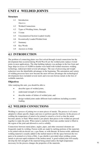
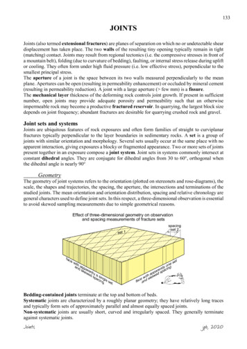
133JOINTSJoints (also termed extensional fractures) are planes of separation on which no or undetectable sheardisplacement has taken place. The two walls of the resulting tiny opening typically remain in tight(matching) contact. Joints may result from regional tectonics (i.e. the compressive stresses in front ofa mountain belt), folding (due to curvature of bedding), faulting, or internal stress release during upliftor cooling. They often form under high fluid pressure (i.e. low effective stress), perpendicular to thesmallest principal stress.The aperture of a joint is the space between its two walls measured perpendicularly to the meanplane. Apertures can be open (resulting in permeability enhancement) or occluded by mineral cement(resulting in permeability reduction). A joint with a large aperture ( few mm) is a fissure.The mechanical layer thickness of the deforming rock controls joint growth. If present in sufficientnumber, open joints may provide adequate porosity and permeability such that an otherwiseimpermeable rock may become a productive fractured reservoir. In quarrying, the largest block sizedepends on joint frequency; abundant fractures are desirable for quarrying crushed rock and gravel.Joint sets and systemsJoints are ubiquitous features of rock exposures and often form families of straight to curviplanarfractures typically perpendicular to the layer boundaries in sedimentary rocks. A set is a group ofjoints with similar orientation and morphology. Several sets usually occur at the same place with noapparent interaction, giving exposures a blocky or fragmented appearance. Two or more sets of jointspresent together in an exposure compose a joint system. Joint sets in systems commonly intersect atconstant dihedral angles. They are conjugate for dihedral angles from 30 to 60 , orthogonal whenthe dihedral angle is nearly 90 GeometryThe geometry of joint systems refers to the orientation (plotted on stereonets and rose-diagrams), thescale, the shapes and trajectories, the spacing, the aperture, the intersections and terminations of thestudied joints. The mean orientation and orientation distribution, spacing and relative chronology aregeneral characters used to define joint sets. In this respect, a three-dimensional observation is essentialto avoid skewed sampling measurements due to simple geometrical reasons.Bedding-contained joints terminate at the top and bottom of beds.Systematic joints are characterized by a roughly planar geometry; they have relatively long tracesand typically form sets of approximately parallel and almost equally spaced joints.Non-systematic joints are usually short, curved and irregularly spaced. They generally terminateagainst systematic joints.Jointsjpb, 2020
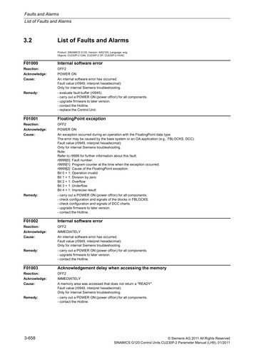
134SpacingThe sizes and spacing (the average orthogonal distance between neighboring fracture planes) areessential characteristics of joint sets. In isotropic rocks (e.g. granite) joint spacing follows anapproximately log-normal frequency (the number of joints occurring within a unit length)distribution. In anisotropic (layered) rocks, joint spacing differs according to several parameters.Bed thicknessFor the same lithology, joints are more closely spaced in thinner beds. This is because the formationof joints relieves tensile stress in the layer over a lateral distance proportional to the joint length. Sincejoints end at layer boundaries, which are rock discontinuities, the longer joints in thicker layers needto be spaced less frequently.Much work has documented linear relationships between average joint spacing, D, and bed thickness,T:D αTThe slopes α are a function of lithology and, by inference, of mechanical properties. However, thislinear relationship might be valid for beds less than 1.5m thick. The slope may change for thickerbeds. A continuous curve with a positive slope and a negative second derivative:acceptably fits all data.Jointsd 2 D dT 2 0jpb, 2020
135However, systematic investigations have shown that the thickness of incompetent interlayersinfluences fracture separation within competent layers. Spacing is wider where interlayers are thickerthan a critical value assessed to be ca 5 cm; conversely, fractures are closer to each other where weakinterlayers are thinner than 5 cm.Spacing scaled with layer thickness is a tool to map lithological contacts, particularly in air-photointerpretation or in the surface mapping of heavily weathered or inaccessible exposures. Spacing mayalso reveal differences in the joint systems at limb and hinge positions on large folds or differentdistances from large faults.LithologyStronger, more brittle rocks have more closely spaced joints than weaker rocks. Similarly, rocks withlow tensile strength show more joints than stiffer lithologies, because the strain is the same alonglayers of different types. Yet, higher stresses are required to achieve the same amount of strain in thestronger layers. Therefore, strong layers fracture more frequently. However, this response isparticularly sensitive to local pore fluid pressure.Structural position and strainThe structural position (particularly within folds) and the magnitude of extensional strain also controljoint spacing.Why joints are evenly spaced?The regular spacing of joints has met several explanations, none of which having been established asa proven mechanism. Yet, nearly all infer that joints form in sequence. Among these hypotheses:Pore pressure / porosity interactionWhen a joint forms, fluids flow into the fracture and the pore pressure in the adjoining rockdiminishes. The local Mohr circle moves away from the failure envelope, and no fracture is possiblenear the initial one. Another fracture can only form beyond the volume of rock with reduced porepressure. The minimum spacing thus depends on the permeability of the rock. This minimum distancewould be the measured finite spacing of joint sets.ExerciseExplain with a Mohr diagram and any given permeability level how pore pressurevariations may control joint spacing.Stress shadowWhen a joint forms, it relieves the tensile stress on either side of the fracture plane that becomes azero-stress surface. Stress builds up gradually away from the fracture until it reaches the remote stresslevel. The next fracture can only form beyond the volume of rock with reduced tensile stress (thestress shadow). The minimum spacing thus depends on the width of stress shadows, hence on elasticproperties of the rock. The uniform spacing is ruled by adjacent stress shadows with joints in themiddle. Stress shadows are larger for longer joints.Inter-layer forcesEach layer is submitted to forces transmitted by adjacent layers. The differential strain between layersexerts tensile stresses in the more competent ones (a process invoked for boudinage). Spacingbetween joints is determined by the length of the layer necessary to build up stresses to the tensilestrength level of the concerned lithology.Joint patternsThere are five main arrangements:- Parallel sets are curved or straight- Fans sets along fold or intrusion crests- Radiate sets around intrusion centersJointsjpb, 2020
136- Concentric sets around intrusion and collapse centers (cone, ring or cylindrical)- Polygonal sets as columnar or prismatic.Master jointsJoints that have dimensions ranging from tens of centimeters to hundreds of meters and repeatdistances of several centimeters to tens of meters are master joints. Besides, most rocks containnumerous inconspicuous joints of smaller size and closer spacing, some of them, the microjoints ormicrofractures, visible only in thin section under the microscope.Joint orientationThe permeability of a fractured reservoir is often highly anisotropic because joints generally form insub-parallel sets. However, more than one fracture set may be present, resulting in a complex fracturenetwork. Knowledge of the spatial distribution and orientation of joints is therefore required tooptimize the development of fractured reservoirs.Joints are measured on a sampling station. The technique aims at measuring their orientation and thefracture density.- A circle is drawn with a piece of chalk attached to a string of determined length (r radius) on aperfectly exposed surface.- One measures the orientation (strike and dip) and length L of each fracture within the circle,marking with the chalk each measured fracture to avoid data duplication. Where dips are notobtained, such as on photographs, orientation data are presented on a rose diagram: Joints in agiven orientation sector (e.g. within 10 ) are counted. A radial line is drawn in the mediandirection of each sector. The length of the line indicates the number of joints occurring in thecorresponding sector.- The joint density is the cumulative fracture length over the circle’s area: ρf L π.r 2In three dimensions, this density (intensity) is the surface area of joint per unit volume of rock.Relative timing of joint formationJoints of the same generation have likely the same orientation. However, rocks experience differentstress regimes during their history with the result that several fracture sets are superimposed on eachother to produce a fracture network. Crosscutting relationships of different joint sets allowdetermining their relative age. Some rules help in this task.- Early joints tend to be long and relatively continuous.- Early joints arrest the propagation and modify the orientation of later ones.Jointsjpb, 2020
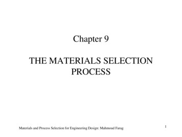
137- As more joint sets develop in the rock, modification of the stress orientation by the pre-existingfractures may result in a poor correlation between the orientation of late joints and the regional stressfield responsible for their formation.Younger joints must terminate against older joints because an extension fracture cannot propagateacross another, older extension fracture. The principal stresses are reoriented near an early joint,which is a free surface unable to support shear stress within the rock and, therefore, is a principalplane of the stress ellipsoid. Consequently, later joints curve into orientation at a right angle to theearlier ones as they approach them and abut against these (abutting relation); younger joints areconsequently shorter. This geometrical observation raises a point of caution: the orientation ofsecondary fractures does not directly reflect the regional stress field.Joint anatomyJoints normally are barren cracks or empty fissures but some may contain coatings. Narrow veinswith infilling minerals, commonly quartz or calcite, are also extension fractures treated as joints.Joint surfacesBarren joints are characterized by clean, granular and jagged breaks. They are conchoidal structures,meaning that they are uneven surfaces with low relief convexities and concavities (like those of aclamshell) that do not follow any natural plane of separation. Such structures are typically seen whenan amorphous material (glass, flint, obsidian, etc.) is fractured. Likewise, some joint surfaces displaydelicate ornaments falling into two groups: plumose-marks, the most common type, and rib-marks.Preservation of these delicate features specifies that the joint is not a shear fracture.Plumose structuresPlumose structures are aggregates of gentle curvilinear undulations (the hackle marks) that radiatefrom the point where the joint originated and fan outward from a generally straight, more rarelycurved axial line, then resembling the shape and imprint of a feather. The origin commonly is somerock heterogeneity such as ripples on bedding planes or inclusions (concretion, nodule, clast, fossil,etc.) in beds. Hackles are often very fine near the joint origin, while the differential relief may amplifylengthwise towards the joint margin (the fringe). Hackles diverge sharply at angles of about 30 fromJointsjpb, 2020
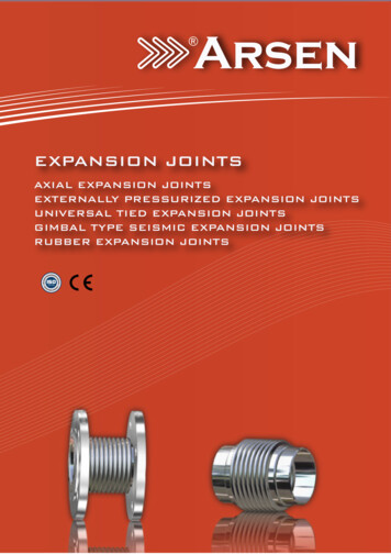
138the central axis, gradually curving to angles of about 70 near the margins of the joint surface. Thescale of plumose patterns seems to depend on the grain size of the rock.Markings similar to plumose structures occur on fracture surfaces in glass and other brittle materials.They are interpreted as surface irregularities due to local variations in the propagation of the fracturefront in terms of velocity and heterogeneities in the rock. Experiments show that the diverging raysof the plumose structures always remain parallel to the direction of propagation of the fracture. Thus,constructing lines at right angles to these rays yields the position and shape of the fracture front atdifferent times of its evolution. The fracture fronts form a series of concentric ellipses, the center ofwhich marks the site of fracture initiation.Rib-marksRib-marks form a series of regular, concentric and arcuate changes or ramps in the orientation of thejoint surface, giving cuspate, waveforms or rounded ridges or furrows. The central zone of rib-marks(the mirror) is often circular or elliptical. Wallner lines are similar to ribs but they occur as one ortwo sets oblique to the hackles.Rib-marks represent changes in fracturing direction as the stress field changes. Experiments haveshown that those that are sinusoidal in profile and smooth on their crests record the location at whichthe velocity of propagation of relatively fast-propagating fractures cutting through a solid materialdiminishes (the stress field is vibrating). Strongly asymmetric rib marks, with sharp crests andoccasionally deviating from parallelism (arrest marks) are associated with slow crack propagation.They are old joint terminations, mapping successive temporary arrests of the crack front duringrepeated crack growth under recurring loading/unloading conditions.InterpretationPlumose and rib marks can be superposed on a joint plane and generally are orthogonal to each other.Such delicate features interlock on opposed faces of joints, and this precludes shear movement (hence,joints are mode 1 fractures parallel to the ( σ1; σ2 ) plane). Plumose and rib marks are a directexpre
A joint with a large aperture ( few mm) . α are a function of lithology and, by inference, of mechanical properties. However, this linear relationship might be valid for beds less than 1.5m thick. The slope may change for thicker beds. A continuous curve with a positive slope and a negative second derivative: d D dT 0. 22 acceptably fits all data. Joints jpb, 2020. 135 However .