Transcription
Thermal Assessment of NaturallyCooled Electronic Enclosures WithRectangular FinsA. Tamayole-mail: ali tamayol@sfu.caF. McGregorM. Bahrami1e-mail: mbahrami@sfu.caMechatronic Systems Engineering,Laboratory for Alternative EnergyConversion (LAEC),School of Engineering Science,Simon Fraser University,Burnaby, BC, V3T0A3, CanadaPassive heat transfer from enclosures with rectangular fins is studied both experimentally and theoretically. Several sample enclosures with various lengths are prepared and tested. To calibrate thethermal measurements and the analyses, enclosures without fins(“bare” enclosures) are also prepared and tested. Surface temperature distribution is determined for various enclosure lengths andheat generation rates. Existing relationships for natural convectionand radiation heat transfer are used to calculate the heat transferrate from the tested samples. The theoretical results successfullypredict the trends observed in the experimental data. It is observedthat the contribution of the radiation heat transfer is on the orderof 50% of the total heat transfer for the tested enclosures. As such,a new correlation is reported for calculating an optimum finspacing for vertically-mounted uniformly finned surfaces, withrectangular straight fins that takes into account both naturalconvection and radiation. [DOI: 10.1115/1.4007077]Keywords: electronic enclosures, conjugate heat transfer, finspacing, natural convection1IntroductionPassive cooling, technologies or design features without powerconsumption, has been used in thermal solutions for various applications such as power electronics, telecommunications, microelectronics, as well as heating, ventilation, and air conditioning(HVAC) systems. Two significant heat transfer modes involved inpassive cooling systems are natural convection and radiation.Convection heat transfer from an object, determined using Newton’s cooling law (Qconv ¼ hAðTs T1 Þ), can be enhanced byincreasing the heat transfer coefficient, h, and/or by increasing thesurface area, A, if the temperature difference is fixed [1].Extended surfaces, which are popularly known as fins, areextensively used in air-cooled heat exchangers and electroniccooling. Although fins increase the surface area, they lead to anincrease in frictional resistance resulting in a lower air flow rate inthe vicinity of the finned surface. At the same time, they add morethermal resistance to the conduction path from the base to the ambient. As such, the heat transfer coefficient for noninterruptedfinned surfaces is lower than the value for the base plate without1Corresponding author.Contributed by the Electronic and Photonic Packaging Division of ASME forpublication in the JOURNAL OF ELECTRONIC PACKAGING. Manuscript received January16, 2012; final manuscript received June 11, 2012; published online July 24, 2012.Assoc. Editor: Amy Fleischer.Journal of Electronic Packagingfins. Therefore, the overall heat transfer rate of a finned platecould either increase or decrease in comparison with the baseplate without fins. These competing trends clearly indicate theneed for an optimization study to establish an ‘optimum’ findesign for air cooled enclosures. The effect of fin-spacing on natural convection has been investigated by several researchers.Design information of natural convection for fin arrays can beextracted from experimental studies of Starner and McManus [2],Welling and Wooldridge [3], Harahap and McManus [4], Jonesand Smith [5], Donvan and Roher [6], Van de Pol and Tierney [7],Yuncu and Anbar [8], and Guvenc and Yuncu [9], as well as thetheoretical works of Bar-Cohen and Rohsenow [10], Baskayaet al. [11], Haddad and Bany-Youness [12], and Dialameh et al.[13]. As a result, several correlations have been reported for theoptimum fin spacing and the natural convection from heat transferrate as a function of geometrical parameters.Radiation heat transfer from a surface located in an ambient oftemperature T1 can be calculated from [1]: 4Fs1 Aer Ts4 T1Qrad ¼(1)Fs1 ð1 eÞ þ ewhere Fs1 is the surface view factor, e is the surface emissivity coefficient, and r is the Stefan–Boltzman constant 5:67 10 8 W m2 K4 . Although fins increase the surface area, theycan block part of radiation from the base plate and adjacent finswhich reduces the surface view factor in Eq. (1). As such, similarto natural convection, radiation heat transfer also depends on thespacing and other geometrical parameters of the finned surface.Radiation heat transfer plays an important role in heat transferfrom fin arrays. This has been shown by Edwards and Chaddock [14],Chaddock [15], Sparrow and Acharya [16], Saikhedkar and Sukhatme[17], Sparrow and Vemuri [18,19], Azarkish et al. [20], and Rao et al.[21]. It has been reported that the radiation heat transfer contributesbetween 25–40% of the total heat transfer from fin arrays.The listed studies have been focused on heat transfer from one single finned plate. Cha and Cha [22,23] investigated laminar steadygravity-driven flow around a single isothermal cube in an infinite medium by employing a control volume finite difference technique. Natural convection from isothermal cuboids and other geometries hasbeen studied by Radziemska and Lewandowski [24,25] and Jafarpourand Yovanovich [26] both experimentally and numerically.In spite of numerous existing studies on natural convection, our literature survey reveals a lack of experimental and theoretical studieson finned enclosures with conjugate natural convection and radiationheat transfer. To cover this ground, passive conjugate heat transferfrom enclosures with rectangular shaped fins has been investigatedtheoretically and experimentally in this study. A custom-designedtestbed has been built to perform the experiments. Several existingfinned enclosures, currently being used by our industrial partner Analytic System Ware (Delta, BC, Canada) have been prepared andtested to assess their thermal performance. The test bed allows temperature and input power measurements needed to assess the steadystate heat transfer from the enclosures. Existing correlations in the literature are used to predict the overall heat transfer coefficient and theaverage temperature of the enclosures under natural convection andradiation heat transfer. The experimental data were in reasonableagreement with the theoretical results. The theoretical analysis isthen used to draw conclusions on the effect of fin spacing on theoverall heat transfer rate of the systems with conjugate heat transfer.2Experimental Approach2.1 Tested Samples. Six electronic enclosures were preparedand tested in this study; the electronic enclosures were made of aluminum by extrusion process. Three enclosures were finned while theothers had the fins milled off down to the level of the bottom of thefin, see Figs. 1 and 2 for more details. During the milling process,no alterations were made that affected the enclosures’ length.C 2012 by ASMECopyright VSEPTEMBER 2012, Vol. 134 / 034501-1Downloaded 02 Aug 2012 to 142.157.144.45. Redistribution subject to ASME license or copyright; see http://www.asme.org/terms/Terms Use.cfm
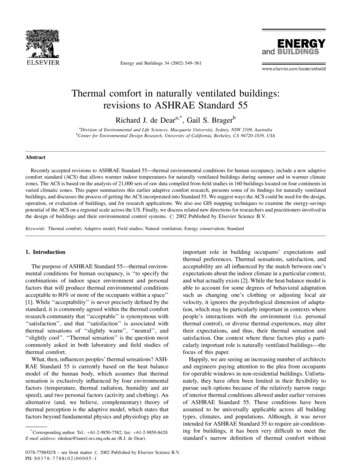
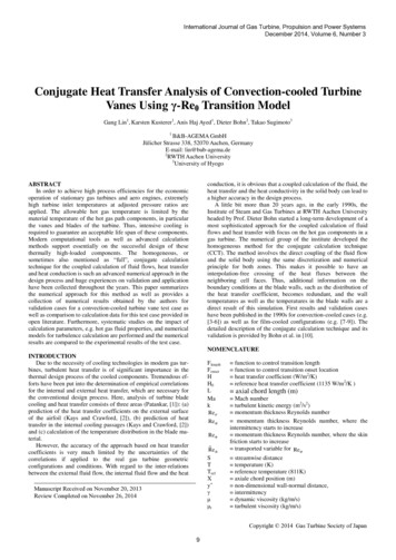
Fig. 1 Schematic of the finned enclosures: (a) cross-sectionview, (b) isometric view, and (c) an actual enclosureThe studied enclosures were used by our industrial partner. Theenclosures’ lengths were 25.40, 30.05, and 40.08 cm.The enclosures’ surface was not uniformly finned; as it can beseen in Fig. 1, they are comprised of unfinned (bare) surfaces andregions with uniformly distributed fins (with 2.5 mm spacing).The width of the bare regions is large enough, larger than 30 mm,such that the surface can be modeled as bare plate. The dimensions of the tested enclosures are listed in Table 1.2.2 Experimental Procedure. Figure 3 shows the schematicand the actual testbed. A wooden board was used to mount theenclosures vertically. The only possible mechanism for unwantedheat transfer was through conduction to the back wall. The gapbetween the wooden board and the enclosure surface was filledTable 1Enclosure nameB10B12B16F10F12F16Fig. 2 Schematic of the bare enclosures without fins: (a) crosssection view, (b) isometric view, and (c) an actual enclosurewith a thick layer of foam for thermal insulation. It was assumedthat the conductive heat transfer through the wooden board wasnegligible in comparison with the radiation and convection heattransfer from the enclosure to the ambient.Enclosure ends were capped with 8 mm thick Poly(methylmethacrylate) (PMMA) plates to provide an airtight seal to theinside, as well as to limit heat transfer from the end regions. Endcaps were cut to match the profile of the extrusion so as not to disturb the gravity-driven airflow.Chromalox strip heaters of 20 cm length were purchased fromOmega (Toronto, ON) and were installed inside the enclosures toDimensions of the tested enclosuresEnclosure typeLength (m)/(in)Fin spacing (m)Finned area (m2)Bare area 0780.0940.126034501-2 / Vol. 134, SEPTEMBER 2012Transactions of the ASMEDownloaded 02 Aug 2012 to 142.157.144.45. Redistribution subject to ASME license or copyright; see http://www.asme.org/terms/Terms Use.cfm
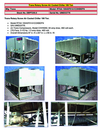
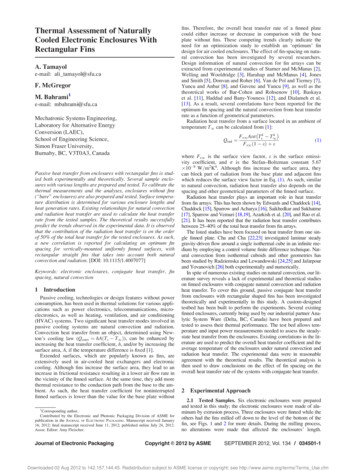
Fig. 4 The maximum and the minimum measured temperatures on the surface of the F10 enclosureFig. 3 Experimental test bed; (a) schematic, (b) distribution oftemperature measuring points and the location of the heaterinside the enclosures, (c) actual test bedsimulate heat generation from MOSFETs. Maximum rated powerof each heater was 150 W. The heaters were powered by an adjustable AC power supply and the consumed power was monitoredduring the experiments. Ten self-adhesive T-type copperconstantan thermocouples with uncertainty of 61 C were installed in various positions on the surface of the enclosures, seeFig. 3(b). All thermocouples were adhered to the inside surface ofthe enclosure to prevent disturbing the outside buoyancy-drivenair flow. An additional thermocouple was used to measure theambient room temperature during the experiments. Each thermocouple is plugged into a TAC80B-T thermocouple to analog converter supplied by Omega (Toronto, ON).The enclosures were tested in a windowless room free of aircurrents. The room temperature was kept constant at 20 C. Eachenclosure was tested at various power levels ranging from 20 to110 W. The heaters were turned on and the surface temperaturewas monitored until a steady state condition is reached, i.e., thepower input was equal to the heat transfer from natural convectionand radiation. Once the variation of the surface temperature wasless than 0.1 C/h, temperatures of all thermocouple were recordedand used in the analysis.Figure 4 shows the maximum and minimum surface temperaturesfor enclosure F10 at various input power (heat transfer rates). Asexpected, the thermocouple closest to the lower edge of the enclosureshowed the minimum temperature, T1; the enclosure temperatureincreased at higher elevations due to thermal boundary growth andthe maximum temperature occurred on the top of the enclosure, T5.3Theoretical Calculations3.1 Enclosures Without Fins. Our experimental measurements showed that the maximum temperature difference along theJournal of Electronic Packagingtested enclosures was less than 8 C. As an example, Fig. 4 showsthe maximum and minimum surface temperatures for enclosureF10 at various input power (heat transfer rates). As such, thesurfaces of the enclosure are assumed isothermal and the arithmetic average of the thermocouple readings is used in the analysis.The air properties are considered to be constant and are calculatedat the film temperature as per the Nusselt number correlationsused. The Nusselt number for natural convection from a plane vertical surface (bare enclosure) of length L can be calculated fromthe following equation [27]:892 1 6 hL0:387RaL¼ 0:825 þ hNu ¼i8 27 k:;1 þ ð0:492 PrÞ9 16(2)where k is the thermal conductivity of air and RaL is the Rayleighnumber based on the enclosures length:RaL ¼gbðTs T1 ÞL3Pr 2(3)where g is the gravity acceleration, b is coefficient of volumeexpansion, is kinematic viscosity of air, and Pr is Prantdlnumber. Nusselt number (and the heat transfer coefficient) is calculated from Eq. (2) and the natural convection heat transfer rateis calculated using Newton’s cooling law [1]. The radiation heattransfer is calculated from Eq. (1) where the view factor Fs1 isassumed to be 1 in this study. Total heat transfer from an enclosure can be calculated from:Qtotal ¼ Qrad þ Qconv(4)Since with the exception of emissivity all other parameters fortheoretical prediction of the heat transfer rate from bare surfaceare known, the experimental data can be used to estimate theemissivity. From comparison of the experimental data with thetotal heat transfer rate, one can estimate the surface emissivitycoefficient to be e ¼ 0.75, for the tested enclosures. This value isin the range of the emissivity values (0.4–0.8) reported for aluminum alloys in heat transfer textbooks; see for example Ref. [1].Therefore, e ¼ 0.75 is considered in all radiation heat transfer calculations including the finned enclosures.SEPTEMBER 2012, Vol. 134 / 034501-3Downloaded 02 Aug 2012 to 142.157.144.45. Redistribution subject to ASME license or copyright; see http://www.asme.org/terms/Terms Use.cfm
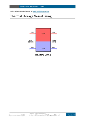
Fig. 5The considered geometry for calculating Fs13.2 Finned Enclosures. For the finned enclosures shown inFig. 1, the total area is divided into two regions: (i) unfinnedregion, and (ii) finned region. The heat transfer in the unfinnedregion is calculated similar to the approach described in Sec. 3.1.Due to a compact spacing and long fins of the tested enclosures,the air flow between the adjacent fins become fully-developedrather quickly; i.e., Lfully-developed/Lenclosure 0.01. As a result,channel flow can be a
the maximum temperature occurred on the top of the enclosure, T 5. 3 Theoretical Calculations 3.1 Enclosures Without Fins. Our experimental measure-ments showed that the maximum temperature difference along the tested enclosures was less than 8 C. As an example, Fig. 4 shows the maximum and minimum surface temperatures for enclosure