Transcription
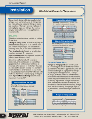
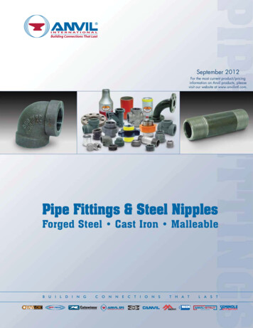
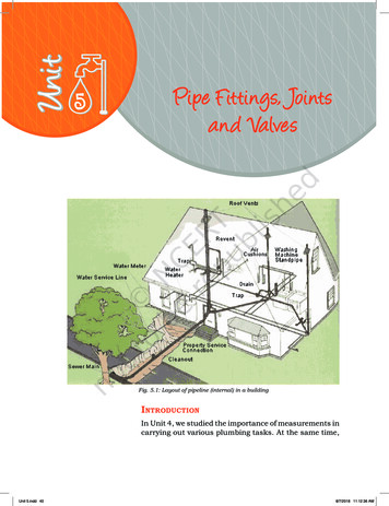
5Pipe F ittings, Jointsand ValvesFig. 5.1: Layout of pipeline (internal) in a buildingIntroductionIn Unit 4, we studied the importance of measurements incarrying out various plumbing tasks. At the same time,Unit 5.indd 408/7/2018 11:12:36 AM
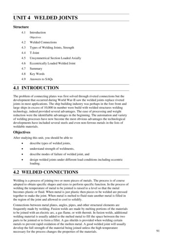
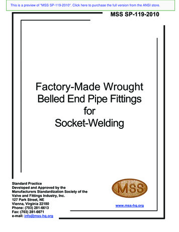
a plumber must also have knowledge of the various pipefittings like elbow, union, gasket, etc., joints and valves,and where these should be used while carrying out thetasks. Not only does this help in smooth functioning, butalso ensures cost-effectiveness. For proper installationof the plumbing system in a building, various types ofjoints are used, which are shown in Fig. 5.1. As alreadymentioned, various types of fittings like elbow, gasket,union, etc., are used for making joints. It helps inchanging the direction of water supply from main pipesto subsidiary pipes. Proper fitting also helps in checkingleakage in the plumbing lines.Pipe FittingsPipe fittings are an important component of theplumbing system. In plumbing, many types of fixturesare joined with the help of various types of material asper the requirement. Fittings are fixed in the plumbingsystem to join straight pipes or any section of tubes. Wecan say that the water-supply fittings like elbow, tee,socket, reducer, etc., are fitted to change the directionof flow, distribute the water supply from the main pipeto other pipes of equal size or lower size, etc.Any part used in connection with water supply,distribution, measurement, controlling, use anddisposal of water is known as a pipe fitting (Fig. 5.2).Fig. 5.2: Pipe fittingsType of cerTeeNippleTrapCollarWhile joining two pipes in the same length, collar isused. Collar is fitted in the end of pipe (Fig. 5.3).Pipe Fittings, JointsUnit 5.indd 41andValvesFig. 5.3: Collars418/7/2018 11:12:36 AM
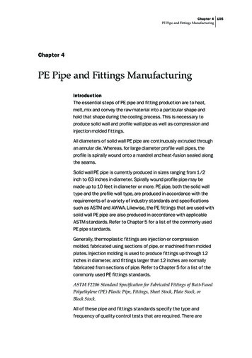
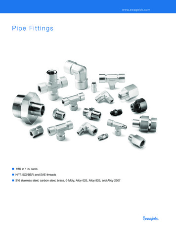
ElbowIt is installed at the time of joining two pipes. With thehelp of an elbow, the direction of liquid is changed.Normally a 45 or 90 elbow is used. When the two sidesof pipes differ in size, an elbow of reducing size is used.This is called reducing type elbow or reducer type elbow.Elbows are categorised as follows—Long Radius (LR) ElbowsHere, the radius is 1.5 times the diameter of pipe.Short Radius (LR) ElbowsIn this, the radius is 1.0 times the diameter of pipe.90 ElbowThis is used when the change in direction required is90 (Fig. 5.5).45 ElbowThis is used when the change in direction required is45 (Fig. 5.4).Fig. 5.4: Bend 45 Fig. 5.5: Bend 90 42Unit 5.indd 42Plumber (General) – Class IX8/7/2018 11:12:36 AM
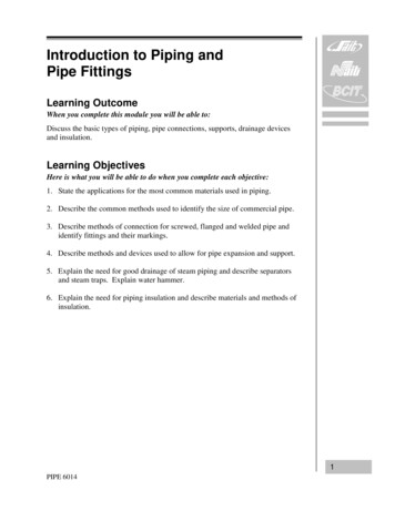
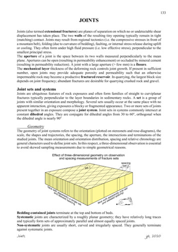
Fig. 5.6: Y-T JointFig. 5.7: Double Y-T Joint-1Fig. 5.8: Double Y-T Joint-2Fig. 5.9: T TrapPipe Fittings, JointsUnit 5.indd 43andValves438/7/2018 11:12:37 AM
GasketFig. 5.10: GasketThey are mechanical seals, generally ring-shaped typeand fitted for sealing flange joints. A flange joint is a plateor ring to form a rim at the end of a pipe when fastenedto the pipe. Gaskets are made as per by construction,materials and features. Important gaskets used are nonmetallic, spiral-wound and ring-joint type (Fig. 5.10).UnionFig. 5.11: UnionWhen two ends of pipes are joined, the pipe fitting usedis called union. A union is made of three parts namely anut, a male end and a female end. The male and femaleends are assembled with the support of the nuts, andnecessary pressure is made to connect the joint. Sincethe pairing ends of the union are interchangeable, theunion can be changed easily in a short time (Fig. 5.11).ReducerIt is used to connect pipes of different diameters. Areducer may be of various types like reducer tee, reducerelbow and reducer socket (Fig. 5.12).Fig. 5.12: ReducersTeeIt is an important fitting with a side outlet at 900 to therun of the pipe. Tees connect pipes of various diametersand help in changing the direction of water or materialin a pipe. Tees are made in various sizes like equal or44Unit 5.indd 44Plumber (General) – Class IX8/7/2018 11:12:37 AM
unequal. The equal tee is most commonly used(Figs. 5.13–5.15).Fig. 5.13: Single tee socketFig. 5.14: Single tee socketFig. 5.15: Double tee socketNippleIt is a piece of pipe having thread at both sides, andcould be used for short extension of plumbing lines. ItPipe Fittings, JointsUnit 5.indd 45andValves458/7/2018 11:12:37 AM
can also be used for connecting two fittings within smalldistance (Fig. 5.16).TrapFig. 5.16: NippleIt is a fitting in a P, U, S or J-shaped type (Fig. 5.17).Traps are fitted near a plumbing fixture. The trap bendis fitted to prevent sewer gases from entering thebuilding. If the gases are inserted back into home,then it could lead to people inhaling foul smell,which could cause illnesses. It could even explode.CrossFig. 5.17: TrapWhen four pipes are joined,a cross is formed. Itis also called a cross branch line or a four-wayfitting (Fig. 5.18). This fitting has three outletsand one inlet. Cross fittings may deteriorate whentemperatures change, because cross fitting is made atthe centre of the four connection points.OffsetFig. 5.18: CrossWhen an assembly of fittings on a pipeline makes onesection of pipe out of line and parallel to a secondsection, then it is known as an offset (Fig. 5.19).LayingWork)Fig. 5.19: OffsetofGI PipesinBuildings (InternalGI (galvanised iron) pipes in the internal work of a buildingare laid either on the surface or concealed in the wall. Forfixing on the surface, the pipes should be kept 1.5 cmapart from the wall and should be laid perfectly vertical orhorizontal. The pipes should be held in pipe clamps whichare embedded in the wall, roof, etc., with cement mortar1:3 (1 cement: 3 coarse sand) (Table 5.1).Table 5.1: Pipe clamp spacingDiameterof pipe(mm)46Unit 5.indd 46Horizontal length(metres)Vertical length(metres)152.002.5202.53.0252.53.0Plumber (General) – Class IX8/7/2018 11:12:37 AM
322.53.0403.03.5503.03.5653.55.0803.55.0NotesThe following points should be kept into considerationduring laying of pipes.1. GI pipes should not come in contact with limeor lime-mortar. They should be treated withanti-corrosive paints.2. Whenever a pipe passes through a wall, provisionof expansion should be made.3. Under the floors, the pipes must be placed in thelayer of sand to allow expansion.Pipe JointsPipes are connected with the help of joints. A variety ofjoints are used in an assembly of pipes. Connecting twoor more pipes together is called a fitting. Various typesof joints could be used in a pipe as per the requirement.Joints are also used for multiple pipe connections, andare an important component of the plumbing system.Generally, the pipe joint fitted can easily sustain thepressure created in the pipe.Types of pipe jointsVarious types of pipe joints are as follows.1. Threaded joint2. Welded joint (butt welded, socket welded)3. Brazed joint4. Soldered joint5. Grooved joint6. Flanged joint7. Compression jointThreaded jointWhen pipes are joined by screwing in threads which areprovided in the pipe, it is called a threaded joint. In thisPipe Fittings, JointsUnit 5.indd 47andValves478/7/2018 11:12:37 AM
joint, one of the pipes has internal threads whereas theother pipe has threads externally. Thethreads are alsomade in various pipes like PVC, CI pipes, copper pipesand GI pipes, etc. (Fig. 5.20).Threaded joints are used from 6 mm diameter to 300mm diameter pipes.Fig. 5.20: Threaded jointWelded joints (Butt-welded joints)It is one of the most common methods of joiningpipes used in large infrastructure like commercial,institutional and industrial systems. Cost of materialare low, but the labour costs are more due to the nonavailability of trained welders and fitters. (Fig. 5.21).Fig. 5.21: Welded jointSocket-welded jointsThese are used when there is a high chance of leakagein the joints. Pipes are joined as putting one into otherand welded around the joint, as shown in Fig. 5.22.Pipes having different diameters are suitable for thistype of a joint. Socket-welded joint gives good results ascompared to other joints.Fig. 5.22: Socket-welded jointFig. 5.23: BrazingBrazed jointsWhen pipes are joined with the help of molten fillermaterial at above 840 C, it is called brazing. Brazing isdone for connecting copper pipes or copper alloy pipes. Itis important to note that the melting point of the parentmaterial (pipe material) should be higher than the fillermaterial. Brazed joints have less mechanical strength,and are preferred in case of moderate temperatures(Fig. 5.23).Soldered jointsFig. 5.24: Brazed andsoldered joint48Unit 5.indd 48Soldering and brazing are similar activities. Insoldering, the filler material melts below 840oC. Withthe help of soldering, copper and copper alloy pipesare joined. During soldering, flux or metal joiningmaterial is used to prevent oxidation due to the flame.Soldered joints are suitable for low temperature areasand have low mechanical strength (Fig. 5.24 andFig. 5.25).Plumber (General) – Class IX8/7/2018 11:12:37 AM
Grooved jointsWhen two pipes are joined together by making grooves(narrow cuts or depression) at the end of pipes withthe help of sockets or couplings, such joints arecalled grooved joints. Due to the ease of assembly ofthe grooved joints, the labour costis less. The piping system can beeasily uninstalled and reinstalledfrequentlyformaintenance(Fig. 5.26). These are mostly usedfor fire protection.Flanged jointsThis joint is commonly used for joining pipes in pumpingstations, filter plants, hydraulic laboratories and boilerhouses, etc. (Fig. 5.27). These joints are preferred dueto easy process of assembly and disassembly, howeverthese connections are costly. These joints can bedisassembled and re-assembled when required. A pipehas flanged ends on both sides of the pipe length. Boththe ends of pipes are joined at a proper level near oneanother. A hard rubber washer is placed between flangesand bolted. Flanges are generally fixed to the pipe bywelding or threading. In certain cases, a flange-typejoint is also called a lap joint. It may also be made byforging the process and machining the pipe end. Thereis no leakage in flanged joints even after rapidtemperature fluctuations.Fig. 5.25: Solder jointFig. 5.26: Grooved jointFig. 5.27: Flanged jointsPipe Fittings, JointsUnit 5.indd 49andValves498/7/2018 11:12:38 AM
Compression jointsFig. 5.28: Compression jointsThese are applied to join the pipe without anypreparations. The cost of installation of these jointsis very economical. The pipes having plain ends arejoined by fixing fittings at their ends, and such a jointis called a compression joint. The pipe ends are joinedwith threaded fittings or couplings. Joints are placedproperly to check the flow pressure, otherwise, leakagemay occur. These fittings are manufactured fromdifferent types of material. Selection of fittings is doneas per requirement (Fig. 5.28).ValvesFor proper functioning of the pipeline, valves madeof iron or brass are used in the water-supply mains.Valves stop or control the flow of fluid like liquid, gas,condensate, etc. These are classified according to theirusage like isolation, throttling and non-return corrector.Various types of valves are manufactured dependingupon their use and type of construction.Sluice valveFig. 5.29: Sluice valveIt is fitted at an important place like at the entrance ofa pipe. It may be the start of a new pipe from a tank,or a number of branches from the tank. This valveisolates the water-supply, as and when required. Thesluice valve is specified by the pipe bore (diameter) ofthe water-way. The standard sizes are 50 mm, 65 mm,80 mm, 100 mm, 150 mm, 200 mm, 250 mm and 300mm. The sluice valves are classified as Class 1 andClass 2 (Fig. 5.29 and Table 5.2).Table 5.2: Test pressure in sluice valveTest Pressurekg/cm2Class50Unit 5.indd 50Max. workingPressure kg/cm2BodySeatClass 1201010Class 2301515Plumber (General) – Class IX8/7/2018 11:12:38 AM
Scour valveThis valve is provided at the lower level in a pipeline,so that such sections can be supplied and drained formaintenance purpose. The water is distributed intonatural drains. It is basically a sluice valve and the verynature of its use has created the difference in the name(Fig. 5.30).Air valveFig. 5.30: Scour valveIt is fitted to release the air automatically when the pipeis filled with water. This valve also permits entry ofair when the pipe is drained. This valve is fixed at theend of a communication pipe and controls or stops thesupply of water. This valve is specified by the standardbore (diameter) of the socket or pipe outlet, to which itis fitted. The standard sizes are 8 mm, 10 mm, 15 mm,20 mm, 25 mm, 32 mm, 40 mm and 50 mm (Fig. 5.31).The body components and washer plate are madeof cast brass or leaded tin bronze. The washers aremade from fibre, leather, rubber or nylon. This valveis available in two types: internally threaded andexternally threaded.Fig. 5.31: Air valveGate valveIt is used for starting or stopping flow. For a straight-lineflow of fluid, minimum flow restriction can also be donewith gate valve. In service, these valves are generally eitherfully open or fully closed. These valves are used for varioustypes of liquids and make a tight seal when closed.Fig. 5.32: Split taper nonrising gate valveTypes of gate valveGate valves have gates of wedge type, solid or split type,or gate of double disc or parallel type. The movementof the gate shall be by the internal or external screwon the spindle. The spindle, which controls the flowof a liquid, can be of the rising or non-rising type. SeeFig. 5.32 and Fig. 5.33.Parallel slide valveIt has two discs without spreading mechanism whichslides between the two parallel body seats. The activationPipe Fittings, JointsUnit 5.indd 51andValvesFig. 5.33: Rising spindle splitwedge gate valve518/7/2018 11:12:38 AM
of the valve discs is by the internal and the externalscrew on the spindle and the spindle may be of therising or non-rising type (Fig. 5.34).Globe valveFig. 5.34: Parallel slide valveIt is a type of valve used
disposal of water is known as a pipe fitting (Fig. 5.2). Type of Fittings 1. Collar 2. Elbow 3. Gasket 4. Union 5. Reducer 6. Tee 7. Nipple 8. Trap Collar While joining two pipes in the same length, collar is used. Collar is fitted in the end of pipe (Fig. 5.3). Fig. 5.2: Pipe fittings Fig. 5.3: Collars Unit 5.indd 41 8/7/2018 11:12:36 AM