Transcription
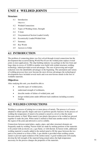
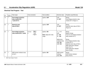
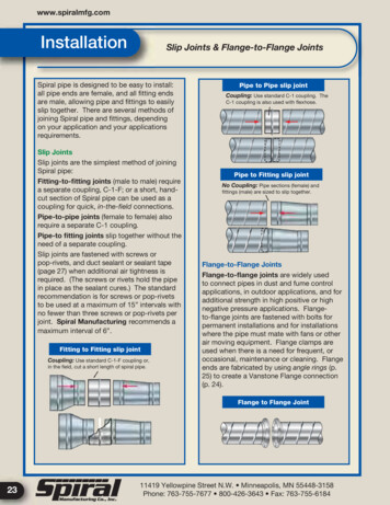
www.spiralmfg.comInstallationSlip Joints & Flange-to-Flange JointsSpiral pipe is designed to be easy to install:all pipe ends are female, and all fitting endsare male, allowing pipe and fittings to easilyslip together. There are several methods ofjoining Spiral pipe and fittings, dependingon your application and your applicationsrequirements.Slip JointsSlip joints are the simplest method of joiningSpiral pipe:Fitting-to-fitting joints (male to male) requirea separate coupling, C-1-F; or a short, handcut section of Spiral pipe can be used as acoupling for quick, in-the-field connections.Pipe-to-pipe joints (female to female) alsorequire a separate C-1 coupling.Pipe-to fitting joints slip together without theneed of a separate coupling.Slip joints are fastened with screws orpop-rivets, and duct sealant or sealant tape(page 27) when additional air tightness isrequired. (The screws or rivets hold the pipein place as the sealant cures.) The standardrecommendation is for screws or pop-rivetsto be used at a maximum of 15” intervals withno fewer than three screws or pop-rivets perjoint. Spiral Manufacturing recommends amaximum interval of 6”.Fitting to Fitting slip jointCoupling: Use standard C-1-F coupling or,in the field, cut a short length of spiral pipe.Pipe to Pipe slip jointCoupling: Use standard C-1 coupling. TheC-1 coupling is also used with flexhose.Pipe to Fitting slip jointNo Coupling: Pipe sections (female) andfittings (male) are sized to slip together.Flange-to-Flange JointsFlange-to-flange joints are widely usedto connect pipes in dust and fume controlapplications, in outdoor applications, and foradditional strength in high positive or highnegative pressure applications. Flangeto-flange joints are fastened with bolts forpermanent installations and for installationswhere the pipe must mate with fans or otherair moving equipment. Flange clamps areused when there is a need for frequent, oroccasional, maintenance or cleaning. Flangeends are fabricated by using angle rings (p.25) to create a Vanstone Flange connection(p. 24).Flange to Flange Joint2311419 Yellowpine Street N.W. Minneapolis, MN 55448-3158Phone: 763-755-7677 800-426-3643 Fax: 763-755-6184
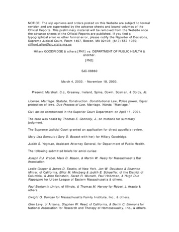
InstallationVanstone Joints & Spiralmate JointsField Installation ofVanstone FlangesSpiral Manufacturing offers professionallymounted Vanstone flanges on Spiral pipe andfittings. For most installations, this is the easiestand most secure option. There may be times,however, when Vanstone flanges must bemounted at the installation site. We have includedmounting instructions below to assist you.Step 1Slip flange over Spiral ductwork allowingduct to extend 1/2” beyond the face of theflange. Measure to ensure the flange is square tothe duct. Secure flange in place with 3 or 4 Cclamps.Step 2Peen 4 tabs about 1” wide and 90 apart, working from the inside of the flange. The edge of theflange acts as a break. Do not cut, slice, or hammer directly on the end of the duct.Step 3Rotate duct 45 and peen 4 more tabs about 1”wide and 90 apart. There should now be a totalof 8 tabs bent over.Step 4Peen remaining edge of duct over flange. Flangeis ready to be bolted.SpiralmateSpiralmate flanges are airtight and easyto install, and no additional sealants arerequired. They can be installed on-site, theyare easy to align, and they use a one-boltclosure. Spiralmate fits Spiral seam and mostribbed pipe, and it accommodates moderatevariations in pipe diameter.Spiralmate is available in diameters from 8” to72” in 2” increments. For one-inch incrementsand sizes larger than 72”, consult the factory.The Spiralmate system is comprised of fourcomponents: two flanges with integral masticinjected into the duct receiving pocket, agasket, and a closure ring and bolt. See photoon page 25.Spiralmate JointsClosure ringGasketFlangeDuct wallMasticDuctrecievingpocketStep 2Duct wallStep 4INNER RING FLANGESOne ring is attached toeach duct end.Spiralmate-S(10” - 34” duct)1 - 1/2”Spiralmate-L(36” - 72” duct)5/8”13/16”Face ofAngleRing1 - 1/4”Face ViewCLOSURE RING appliespressure to Inner Flange Ringsto form a permanent airtightconnection.1 - 1/4”Duct wallSEALANT permanent nonhadrdening mastic injectedin during manufacture.GASKET Ductmate Neoprene gasket is applied toflange face before joiningduct.FASTENER formsa permanent attachment betweenflange and duct.See Page 25 for sizes.24
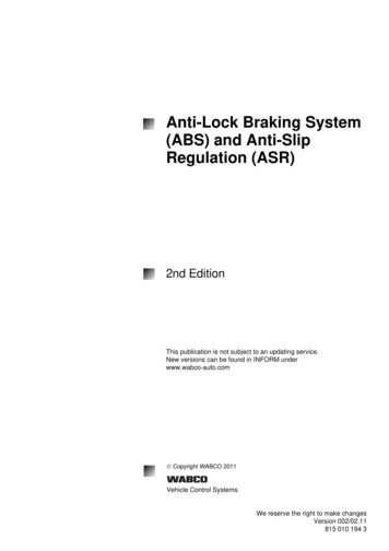
oltHoleCentersNo. ofBoltHoles31/16”7 8/”1”10 Ga.45/16”69 32.7041/16”15 161”10 Ga.55/16”69 32.855 16/ ”/ ”/ ”5/ ”1”1”10 Ga.6/ ”69 32/ ”1.2061/8”11/4”11/4”10 Ga.71/2”63 81.751 87/”1 41/”1 41/”10 Ga.1 28/”63 82.0081/8”11/4”11/4”10 Ga.91/2”83 82.2591/8”11/4”11/4”10 Ga.101/2”83 82.5010 / ”1 41/”1 41/”10 Ga.11 / ”83 82.75111/8”11/4”11/4”10 Ga.121/2”83 83.00123/16”11/2”11/2”10 Ga.1313/16”127 164.00133/16”11/2”11/2”10 Ga.1413/16”127 164.25143/16”11/2”11/2”10 Ga.1513/16”127 164.7515 / ”1 21/”1 21/”13 1616 / ”167 165.0163/16”11/2”11/2”3 16181/8”167 168.0173/16”11/2”11/2”3 16191/8”167 168.2518 / ”1 21/”1 21/”3 1620 / ”167 168.50203/16”11/2”11/2”3 16221/8”207 169.50223/16”11/2”11/2”3 16241/8”207 1610.7524 / ”1 21/”1 21/”3 1626 / ”207 1611.50263/16”2”2”3 16281/2”247 1616.5018.003 163 163 1610 Ga./ ”/ ”/ ”/ ”/ ”/ ”/ ”1 21 81 8/”/”/”/”/”/ ”/ ”/ ”/ ”/ ”/ ”/ ”/ ”/ ”/ ”/ ”28 / ”2”2”3 1630 / ”247 16303/16”2”2”3 16321/2”287 1619.50323/16”2”2”3 16341/2”287 1620.0036 / ”327 1622.50381/2”327 1623.0024.503 16/ ”/ ”/ ”24 / ”2”2”3 16363/16”2”2”3 163 16/ ”/ ”1 2/”1 2/ ”/ ”/ ”/ ”38 / ”2”2”3 1640 / ”367 16403/16”2”2”3 16421/2”367 1625.75423/16”2”2”3 16441/2”407 1626.5028.003 16/ ”/ ”/ ”1 2/ ”/ ”/ ”44 / ”2”2”3 1646 / ”407 16463/16”2”2”3 16481/2”447 1629.00483/16”2”2”3 16501/2”447 1630.75/ ”/ ”/ ”Spiralmate Flange1 2/ ”/ ”/ ”/ ”Angle Rings(Pressed or Rolled Steel)Weight(lbs.)1 163 16ROLLED ANGLEDia. ofBoltHolesInsideDia.1 825Angle Rings, Flange Clamps & Spiralmate Quick SleevePressed and rolled steel anglerings are used widely in joiningductwork together in dust andfume control work. All rings areunpainted, mild steel (Galvanizedand Stainless Steel available). Theyare available with or without holes.Dimensions shown are typical.Nearly any bolt circle or hole size isavailable. Consult Factory.Cross SectionWI.D.WTHB.H.C.Side ViewFace ViewFlange Clamps11419 Yellowpine Street N.W. Minneapolis, MN 55448-3158Phone: 763-755-7677 800-426-3643 Fax: 763-755-6184
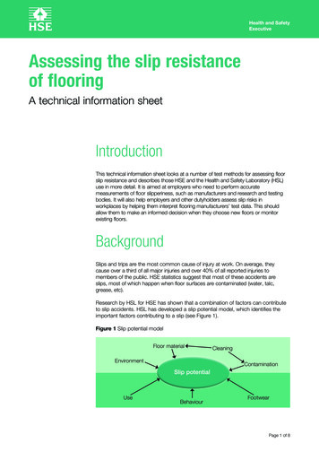
Tools, Tek-Screws & DriversAviation SnipsInstallationComponentsKJS1 – Right hand Made of hard Molybdenum/Silicon tool steel forgood cutting edge and longer tool life Double-cam-action construction for 20% greatercutting power with less effort, maximum opening ofjaws, minimum opening of handles Serrated blades - Draw work into cutting edgeswithout slipping, for accurate, clean cuts Higher leverage, spring-action handles Hardened pivot bolt; safety latch; self-locking nuts Soil and wear-resistant PVC grips Left hand model - green - cuts right Right hand model - red - cuts left Straight - yellow - cuts straight and slight curvesKJS2 – Left handAviation Snips Ordering InformationModel No.DescriptionLengthCutKJS1Right hand9–1/2”1–1/4”3.2 cmKJS2Left hand9–1/2”1–1/4”3.2 cmTek-Screws and DriversTek-Screws: Used as a self-drilling screw they eliminate all hole preparation. Tek-Screws can be usedwith or without pilot holes. Positive rake forwardcutting edges drills straight thru sheet metal at peakspeed. Perfectly mated threads increase strip andback out pressures. Used extensively by installers ofheating and ventilating duct to produce sheet metalassemblies faster and more securely.GuaranteeEvery Klenk Tool carries a lifetimeguarantee against breakage. Shouldthe blades break in normal use, thetool will be replaced by the Klenkdistributor, or may be returned tothe factory for repair or replacement.Factory reconditioning and resharpening service is also available at a verynominal charge.Tek-Screw#8 x 1/2”Tek-Screw Driver (TSD)1/4” driver for #8 Tek-ScrewAvailable in quantities of50, 100, 500, 100026
www.spiralmfg.comSealants & TapesDuct Sealant & Aluminum Foil Tape601 Duct Sealant321 Duct SealantPremium Indoor/Outdoor FlexibleWater Based Duct SealantFiber reinforced Indoor/OutdoorWater Based Duct SealantA versatile, all purpose, fiber-free, duct sealantfor use on all types of metal duct, glass fiber ductboard, flex duct, duct fabric and flexible tubingrunouts. Distinguished by its ability to accommodateminor vibration and movement, S2 - 601 staysflexible to save call-back labor. S2 - 601’s excellentcoverage and easy brush-on application provide lowinstallation cost while providing proven reliability.Specifications Compliance: Passes ASTM C-731,ASTM D-2202. USDA, EPA and FDA Approved.S2 - 321 is an all purpose industrial grade ductsealant for all types of metal duct, glass fiber ductboard, and flex duct, as well as duct fabric andflexible tubing runouts. It includes UV inhibitorsfor extended outdoor exposure and built-in fiberreinforcement for added strength. This non-toxicwater based product is solvent free and is suitablefor residential use.Specifications Compliance: Passes ASTM D-2202,ASTM C-731. USDA, EPA and FDA ApprovedApplication Data for 601 and 321 Duct SealantsColor. GrayApplication/Storage Temperature .35 F to 110 FService Temperature.- 20 F t0 200 FPressure Classes . SMACNA 1/2, 1, 2, 3, 4, 6 and 10 inches w.g.Seal Classes. SMACNA A, B , CMethod .Brush, putty knife, caulk gun, pumpRate. Apply at joint and fastener to 20 mil thick wet film after duct work installedClean up (wet) .Soap and waterPackaging . 10 ounce tube; 1 gallon canCoverage (1 gallon) . 500 feet x 2 inches wideCoverage (1 tube). 65 feet at 1/4” bead; 130 feet at 1/8” bead601 & 321 Gallons601 & 321 Tubes1520CW Alum. Foil Tape1402AFQ Sealant TapeAluminum Foil TapeProduct/Description1520CWDead-soft alumiumfoil; Silicone releaseliner.1402AFGMill finish alum.substrate with grayadhesive sealant27Color-SizeAluminum-2” x50ydsAluminum or Paintable-2” x 100ft.AdhesiveThickness/TensileStrengthCold WeatherAcrylic3.5 mil27 lbs/inch width100% solid elastrometric modifiedbutyl2 mil Aluminum, 15mil Gray Matter955 psi avg.Peel Adhesion/ServiceTemp.96 oz. per in. width-35 F to 260 F16 lbs. per lin. Inch35 F to 110 FU.L. Listed/Flame Spread/Smoke Devop.PressureClass/Seal ClassPrecautions723 Class A510NoneNone723 Class A2040SMACNA 1,2,3,4and 6 inches w.g.SMACNA A,B,CYesSee MSDS11419 Yellowpine Street N.W. Minneapolis, MN 55448-3158Phone: 763-755-7677 800-426-3643 Fax: 763-755-6184
Single and Double Rod Hangers, Nuts,Washers & Threaded RodsWeights and Sizes of Single and Double Rod oriesSingle Rod9/16” holesstandard onDouble RodWall MountSizes thru 20” are 1-1/2” x 16 gaugeSizes 22” and above are 2” x 14 guageVertical DuctsMaximumDiameter ofRound DuctsStraps DescriptionHardware supplied upon request.10”0.047” (No. 18 guage) galvanized steel 2” wide 10’ by 1’’ Hanger Strap, 16 guage,25 per bundle.20”0.058” (No. 16 guage) galvanized steel 2” wide*40”1/8” steel x 1-1/2”*60”1/8” steel x 2”*Over 60”3/16” steel x 2”* 100’ by 3/4’’ Hanger Band Rolls,24 guage, slotted.Hex Nut(Plated)Flat Washer(Plated)* Spaced vertically not more than 12 ft. on centersHorizontal DuctsMaximumDiameter ofRound DuctsStraps Description10”Same gauge as galvanized steel duct, 1’’ wide or(No. 8 gauge galvanized steel wire) on 10’ centers20”40”60”Over 60”Same gauge as galvanized steel duct, 1’’ wideor (No.8 gauge galvanized steel wire) tied to 1’’galvanized steel band around duct on 10’ centersSame gauge as galvanized steel duct, 1-1/2’’ wideon 6’ centersSame gauge as galvanized steel duct,1-1/2’’ wide on 4’ centersReproduced from International Uniform Mechanical Code. As localcodes differ, it is the responsibility of the user to determine thathangers listed will satisfy local regulations. Spiral Manufacturing Co.,Inc. assumes no responsibility other than the sizes and materiallisted in the Spiral Standard Hangers table above.3/8”-16 and1/2” - 133/8” and 1/2”Coupling(Plated)3/8”-16 and1/2” - 13by 1-3/4” longThreaded Rod3/8”-16 and 1/2”-13Length: 36” and 72”28
www.spiralmfg.comHangerAccessoriesBeam clamps, struts & Speed Link Sammy Screws (BCW)Universal Support SystemSammy screws aredesigned to quicklyfasten threaded rodto wood beams andtrusses. They areavailable in 3/8” and1/2” sizes.The Universal Support System is a standalone hanging system that supports a widevariety of applications.Beam Clamp(Model 300 (BC)Malleable iron casting with a hardened cuppoint set screw and locknut. UL listed. Setscrew must be tightened onto the sloped sideof the I-Beam, cha
coupling for quick, in-the-fi eld connections. Pipe-to-pipe joints (female to female) also require a separate C-1 coupling. Pipe-to fi tting joints slip together without the need of a separate coupling. Slip joints are fastened with screws or pop-rivets, and duct sealant or sealant tape (page 27) when additional air tightness is required. (The screws or rivets hold the pipe in place as the .