Transcription
Metal Expansion JointExpansionJoints
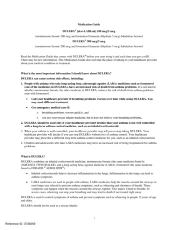
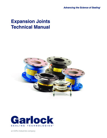
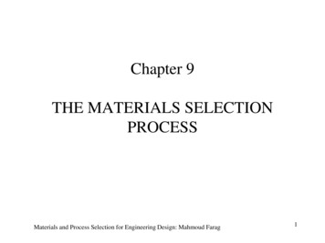
METAL EXPAMegaflexon Advantagemegaflaxon’s metal expansion joints detailed calculationsused to design the joint in accordance with EJMAstandards. megaflaxon maintains quality assuranceprograms in accordance with the standards and requirementsof innovative designs.ASME SECTION Ⅷ(Nuclear), ANSI B 31.1 and ANSI B31.3, the Expansion Joint Manufacturer’s Associationstandards, ASME section ⅢApplicationsNuclear power generation, Fossil fuel power generationindustry, petroleum refining, petrochemical industries, LNG,cryogenics, Heat exchangers, Boiler & TurbineExhaust with high quality and service1400 ID Dual tied gimbal expansion joint.34″NOM. Universal expansion joint with pantograph linkagecold wall design(resid catalytic cracking-convertor section)DN1356/1538 Double gimbal expansion joint. with saddlehardware and mitre elbow attachment36″NOM. Hinged expansion joint(resid catalytic cracking-convertor section)Flange & Flued Type Expansion JointFlange & Flued Type Expansion Joint
NSION JOINTINNOVATIVE DESIGNSAll applicable American, European andinternational code and standards such asASTMASMEEJMA LATEST EDITIONBSISO 9001APIDouble gimbal expansion joint(ID 1650) with tee conns & dishedendsDouble gimbal expansion joint(ID 1650) with tee conns & dishedends30″Tied universal expansion joint for ground settlement(pre-set : 100mm)100″6000mml Universal Type Expansion Joint36″Dual Gimbal Type Expansion JointMetallic rectangular expansion joint for flue gas line,11182 3482 3000 mmLDouble miter coner type / intermediate pipe, sleeve:A387Gr12
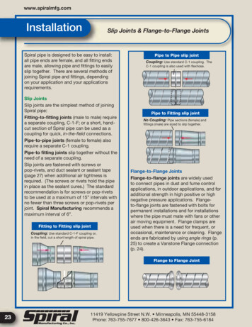
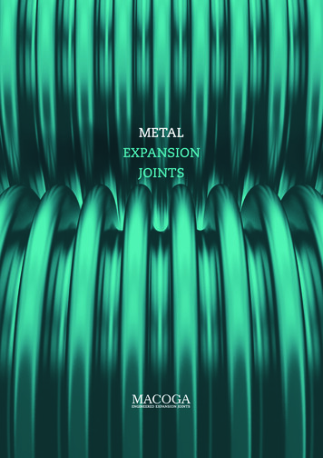
METAL EXPATied Universal Type Expansion Joint (120″))Gimbal & High Type Expansion Joint (50″)Pressure Balance Type Expansion Joint (92″InlinePressure Balance Type Expansion Joint (84″)Tied Universal Type Expansion JointDual Hinge Type Expansion Joint (36″/ Alloy 600Material)Installation and Servicemegaflexon is recognized as leader in the expansionjoint As such, in-depth knowledge of the productsand technology allow us to perform installation,inspection for leakage, maintenance and repairs.megaflexon provides experienced problem solvingfield service in expansion joint installation withskill engineer and technological experience inthermal movement.
NSION JOINTINNOVATIVE DESIGNSL- Type Pressure Balance Expansion Joint (84″ 6600mmL)Dual Gimbal Type Expansion Joint (24" 1936 mmL)Special Type Tied Univesal expansion joint (34″ 9400mmL)DN1538 Dual Gimbal Type Expansion Joint Transportationby AirMegaflexon manufacturers bellowes from Stainless steel 300 series - 304, 304L, 316, 321, 317L Stainless steel 400 series - 430, 410, 437 Titanium Alloy 600, 625, 625LCF Alloy 800, 800H, 825 Alloy 718, 750 Alloy 400 Hastelloy B & C Nickel 200Megaflexon expansion joints offers ;Round typeRectangularOval & special shapes type
6
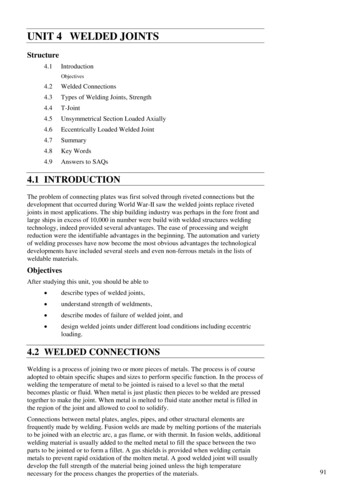
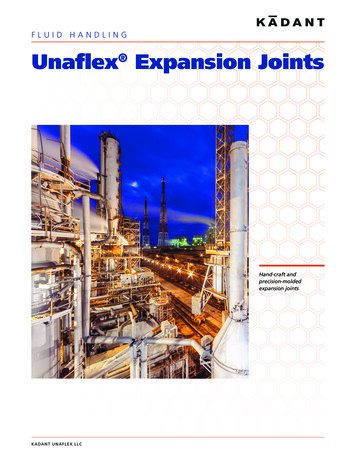
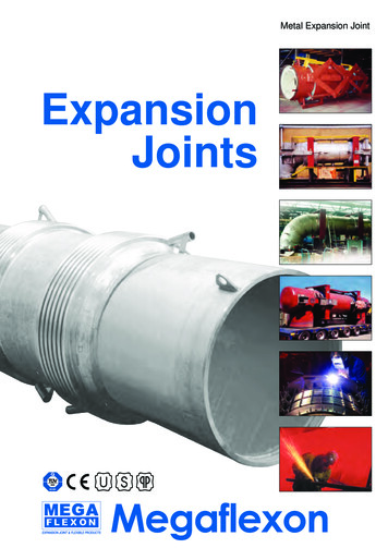
EXPANSION JOINT & FLEXIBLE PRODUCTExpansion JointsFabrication procedureCutting of the thin bellows layersRolling on roller bending machineWelding of the outer and inner layerRadiography & Liquid Penetrant testpolishingPreparation of the and weldedinner and outer layerMultiply bellows, with4 welded layer2ND1STRoll forming by wheelor hydraulic powered formingMultiply expension bellowsafter formingEdge CuttingPneumatic testHydrostatic testHeat resistant paint coatingWeld attachment to theshell, or fittings7
1.Expansion JointThe selection of the optimum expansion joint depends on a technical as wellas an economical aspect.With many years of experience in design, production and marketing ofexpansion joints, we are competitive and specialized on the know-how on thesolution for demand required in a technical and economical view.Therefore, it will always be highly appreciated to contact to us in case that youneed our assistance.We look forward to serving you.2.ApplicationEngineering products, expansion joint & flexible products, which can absorbthermal and mechanical movements in pipe-work and duct systems, providesolution to engineering problems all over the world. Application are as diverseas there are industries.There are applications inProcess EngineeringPower Generation allurgyNuclearHeating Ventilating and A/CAerospaceAutomotiveCombustion Engine3.The BellowsThe bellows is the basic element of expansion joint, which can be made bymechanical and hydraulic forming as the requirement in MEGAFLEXON facility.The mechanical forming, which is also known as roll forming, involves passingthe tube through progressively deeper convoluted mandrels and gradually andcause realy fatigue failure by friction due to the concentration of local hardness.MEGAFLEXON can produce up to 8,000mm size as per the requirement.The hydraulic forming is a method in which forming tube is slowlycompressed with low hydraulic pressure towards the inside after placingrestraining rings around the forming tube and sealing both ends, andsubsequently it leads to producing far better qualitive product than the8
EXPANSION JOINT & FLEXIBLE PRODUCTmechanical forming does as it gives uniform hardening all over the world. Inthis method, MEGAFLEXON can produce up to 1,500 mm in nominal diameter.All bellows are formed in their cold state without heat treatment but it can beheat treated, in case that specially required.The physical capacity of bellows to absorb movement is determined by thenumber of corrugations, height (H), pipe diameter (D), spacing (L), radius (r),thickness of material (t), and number of layers (n).The basic constituent element of expansion joint, bellows, can be specified,considering on movement, pressure, temperature, service life and corrosionrate required.Our standard material for the circular type bellows is austentic steel, that is, AISI304 and 316. In addition, other special Nickel based alloy material, like as Inconel,Incoloy, Monel and Hasteloy, can be applied on the servicing of agressive fluid.The below can be helpful for yourconsideration on bellows and othermain part material of expansionjoint for the selection as per thespecification required.Basically, austenitic steel is resistant to both high temperature anda agressive media. It has a goodmechanical properties as well whenit comes to the effect of continuousmotion in axial, lateral and angulardirection.MEGAFLEXON bellows have been improved to achieve an optimizedrelationship between the various parameters, so that the bellows can withstandthe greatest possible load without fail on normal operating condition.Basically, we carefully consider following criteria in designing bellows.a) The geometrically stable state in a hydro test pressure of 1.5 times designpressure.b) The stability for a hydro-test pressure of 1.5 x design pressure at leastwithout permanent changes in shape of leaks develops.c) The reliable warranty service life of at least 7,000 cycles with nominal9
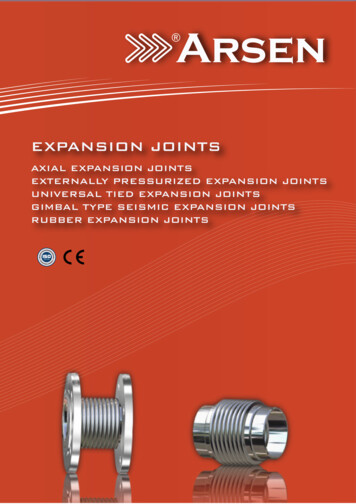
movements and design pressure.d) Calculation for bellows designs are carried out to be in accordance withEJMA (Standard of the Expansion Joint Manufacturers Association)Ⅴ. Ⅵ. Ⅶ Edition.It is essential that the weld in the bellows be as strong as the surroundingmaterial.Welding is done by qualified welders using machines specially built for thepurpose. Welds comply with every metallugical requirement with regard todurability and strength, documented by the certified procedure test.4.The thermal expansion of pipeThe extent of expansion depends on the temperature difference, the expansioncoefficient and the length of the pipe. The expansion coefficient varies from onematerial to another and is also dependent on the temperature, as it increase asthe temperature rises.The coefficient list, graphical chart and calculation example are shown on theReference Data. H.5.Installation instruction for MEGAFLEXON axial expansion joints.Pipe layingOn installing pipelines, care should be taken that the pipe is laid in a straightline. Fixing points should be located in such a way that the pipe expandscorrectly in relation to the type of expansion joint chosen.5.1 GuideEspecially, to operate the expansion joint effectively and positively, a guidepipe which slides smoothly with less friction should be provided between thefixing point and the expansion joint. The distance between the expansion jointand the guide adjacent therto should be determined to be L1, L2 shown in fig.5.2 Guide bearingsGuide bearing, which protect the pipe-work against bending in all directions,should be of the slide or roller type. Pendent suspension is not recommended.Only one axial expansion joint may be fitted between 2 fixing points. Guidebearing should be placed at the maximum intervals.10
EXPANSION JOINT & FLEXIBLE PRODUCT5.3 Fixing points, or main anchorPipelines in which expansion joints are to be installed should be secured withfixing points. The fixing points must be sturdly enough to absorb the forcesoriginating from the expansion joint and the frictional resistance of the guidebearing.That is, stress on the main fixing point Fh is composed of the resulting forcescoming from;a) The spring constant Ca, which is the force it takes to move the bellows1 mm axially or laterally. Since the spring constant is a theoretical calculation, a deviation of - 30% from the values specified on the data sheetsmust be expected.b) Tensile stress from the highest operating pressure of P bar affecting theactive area Ab mm2 of the bellows.Nominal80 100 125 150 200 250 300 350 400 450 500 600 800 1000 1200 1500 1800Dia (mm)L1 (m)0.3 0.4 0.5 0.6 0.8 1.0 1.2 1.4 1.6 1.8 2.0 2.4 3.24.04.86.07.2L2 (m)1.1 1.4 1.8 2.1 2.8 3.5 4.2 4.9 5.6 6.3 7.0 8.4 11.2 14.0 16.8 21.0 25.2100L3 1.571·100EI·10-3 . (37)PA Fex807001800150 51010080INTERMEDIATE GUIDE SPACING L3(M)60L3 Maximum intermediate quide space(M)E Young's modulus of pipe material(kg/mm2)I Moment of inertia of pipe(mm4)P Design pressure(kg/Cm2)A Bellows effective area(mm2)F Bellows initial spring rate per onecorrugation(kg/mm/corr.)ex Axial stroke of bellows per onecorrugation(mm/corr.)5When bellows is compressed in operation,use( ) F·ex ;when extended, use(-) F·ex 30252015107543.5MAX.WORKING PRESSURE(kg/cm2)11
c) The inherent resistance of the expansion joint, which is the product of thespring constant kgf/mm and the expansion for the section of pipe.d) Addition for friction force from guides between two fixing points.Stress on intermediate fixing points Fm is calculated as the sum of the abovestresses b) and c), since tensile stress for the same pipe dimension is entirelyabsorbed by Fh.5.4 Pre-stressingMEGAFLEXON standard expansion joints are dimensioned to absorb /movements from the neutral position of the bellows, with half being absorbedby each: /- 20 mm 40 mm total movement, /- 7 Deg. 14 Deg. totalmovement. It is possible to pre-stress the expansion joint in order to make fulluse of the working range of the bellows. If calculation show that a totalmovement of 30 mm should be used, it is possible to use to advantage an expansion joint with /- 15 mm movement which has been half percentprestressed to 30mm instead of an expansion joint with /- 30mm movement.It should be noted, however, that it is not wrong to use an expansion joint witha movement of /- 30mm.The following parameters should be taken into account when verifying prestressing.1) The overall dimensions at installation temperature2) The neutral length of the expansion joint before prestressing3) The total movement of the expansion4) The highest operating temperature to occur5) The lowest operating temperature to occur6) The installation temperatureIt is very important that the expansion joint is installed in its optimumposition, as this will produce the best combination of movement and service lifein the bellows.12
EXPANSION JOINT & FLEXIBLE PRODUCT6.Method of SettingPlease take NOTE of the following matters with respect to the operation ofexpansion joint.6.1 Removal of set boltExpansion joint is provided with a set bolt or set bar that is painted yellowsand used for adjusting dimension. Always remove this set bolt after piping incompleted.6.2 Inhibition of gas cutting of set boltAlways use wrench for removing the set bolt.Absolutely avoid gas cutting since if frequently may damage bellows.6.3 Protecting from welding sparkDo not allow welding spark and grinder spark to come into direct contactwith bellows. Always cover the bellows when you carry out these operationsnear the expansion joint.6.4 Prohibition of arc in continuity testAbsolutely avoid the contact of electrode and earth wire with bellows in thecontinuity test.6.5 Direction of flowGenerally, the direction of flow is defined. Mount the joint in the direction ofarrow. Take care where the direction of flow is not restricted, as is the case ofhinged type, universal type, etc.6.6 Direction of mounting hinged typeParticularly in the hinged type, hinge arm is mounted on both side of bellows.Hence, mount the hinge arm parallel to the direction of expansion andcontraction.6.7 PresetGenerally the expansion joint is set, taking the mounting temperature intoconsideration. Please contact us when the application and the temperature areremarkably different form those set.6.8 Use caution with sea waterTake care of installation site and maintenance since, particularly, STS-304 iseasily affected by sea water (Cl ion). Contact us before you install it for seawater piping.13
DESIGN OF EXPANSION JOINT Requirements for the DesignThe following are requirements for the design of the Expansion joint.These requirements shall be fulfilled through your inquiry.1. Pipe size2. Standard of pipe,wall thickness, materialStandard of pipe(SPP, SPPS38, SPW, etc.), schedule no. In thecase of nonstandardized pipe, outside(or inside) diameter,wallthickness, material.3. ConnectionBeveling configuration(distinction between internal and external,angle, etc.) in welding, standards, dimension, m
DN1356/1538 Double gimbal expansion joint. with saddle hardware and mitre elbow attachment Flange & Flued Type Expansion Joint Flange & Flued Type Expansion Joint 34 NOM. Universal expansion joint with pantograph linkage cold wall design(resid catalytic