Transcription
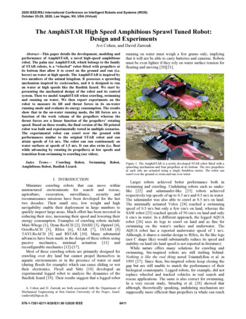
2020 IEEE/RSJ International Conference on Intelligent Robots and Systems (IROS)October 25-29, 2020, Las Vegas, NV, USA (Virtual) The AmphiSTAR High Speed Amphibious Sprawl Tuned Robot:Design and ExperimentsAvi Cohen, and David ZarroukAbstract—This paper details the development, modeling andperformance of AmphiSTAR, a novel high-speed amphibiousrobot. The palm size AmphiSTAR, which belongs to the familyof STAR robots, is a “wheeled” robot fitted with propellers atits bottom that allow it to crawl on the ground and run (i.e.hover) on water at high speeds. The AmphiSTAR is inspired bytwo members of the animal kingdom. It possesses a sprawlingmechanism inspired by cockroaches, and it is designed to runon water at high speeds like the Basilisk lizard. We start bypresenting the mechanical design of the robot and its controlsystem. Then we model AmphiSTAR when crawling, swimmingand running on water. We then report experiments on therobot to measure its lift and thrust forces in its on-waterrunning mode and evaluate its energy consumption. The resultsshow that in the on-water running mode, the lift forces are afunction of the work volume of the propellers whereas thethrust forces are a linear function of the propellers’ rotatingspeed. Based on these results, the final version of the 3D printedrobot was built and experimentally tested in multiple scenarios.The experimental robot can crawl over the ground withperformances similar to the original STAR robot and canattain speeds of 3.6 m/s. The robot can run continuously onwater surfaces at speeds of 1.5 m/s. It can also swim (i.e. floatwhile advancing by rotating its propellers) at low speeds andtransition from swimming to crawling (see video).running on water must weigh a few grams only, implyingthat it will not be able to carry batteries and cameras. Robotsmust be even lighter if they rely on water surface tension forfloating and moving [20][21].Index Terms— Crawling Robot,Amphibious Robot, Basilisk Lizard.Figure 1. The AmphiSTAR is a newly developed STAR robot fitted with asprawling mechanism and four propellers at its bottom. The two propellersat each side are actuated using a single brushless motor. The robot cancrawl over the ground or swim and run over water.SwimmingRobot,I. INTRODUCTIONMiniature crawling robots that can move withinunstructured environments for search and rescue,agriculture, excavation, surveillance, security andreconnaissance missions have been developed for the lasttwo decades. Their small size, low weight and highnavigability enable their deployment in large numbers toquickly inspect large areas. Much effort has been invested inreducing their size, increasing their speed and lowering theirenergy consumption. Examples of crawling robots includeMini-Whegs [1], Dyna-RoACH [2], DASH [3], iSprawl [4],OctoRoACH [5], RHex [6], STAR [7], 1STAR [8]TAYLRoACH [9] and RSTAR [10]. Many substantialadvances have been made in the design of these robots usingpassive mechanics, minimal actuation [11] andreconfigurable mechanics [12]-[17].Most of these crawling robots are primarily designed forcrawling over dry land but cannot propel themselves inaquatic environments or in the presence of water or mud(during floods for example) which can cause sliding or wettheir electronics. Floyd and Sitty [18] developed anexperimental legged robot to analyze the dynamics of theBasilisk lizard [19]. Their results suggest that a legged robotA. Cohen and D. Zarrouk are both associated with the Department ofMechanical Engineering at Ben Gurion University of the Negev, Israel.(zadavid@bgu.ac.il).978-1-7281-6211-9/20/ 31.00 2020 IEEELarger robots achieved better performance both inswimming and crawling. Undulating robots such as snakelike [22] and salamander-like [23] robots achievedrespectively top speeds of up to 0.3 m/s and 0.5 m/s in water.The salamander was also able to crawl at 0.5 m/s on land.The minimally actuated Velox [24] reached a swimmingspeed of 0.5 m/s but only a few cm/s on land, whereas theSAW robot [25] reached speeds of 50 cm/s on land and only6 cm/s in water. In a different approach, the legged AQUArobot [26] uses its legs to crawl on land and as fins forswimming on the water's surface and underwater. TheAQUA robot has a reported underwater speed of 1 m/s.Although, it shares a similar design to RHex, its fin like legs(not C shape like) would substantially reduce its speed andstability on land (its land speed is not reported in literature).While nature offers many solutions for crawling andswimming, bio-inspired robots are still trailing behind.Nothing is like the real thing noted Triantafyllou et al. in1995 [27]. Since then, bio-inspired robots keep closing thegap but are still unable to match the performance of theirbiological counterparts. Legged robots, for example, did notreplace wheeled and tracked vehicles in real search andrescue applications. The same is also correct for swimming.In a very recent study, Struebig et al. [28] showed thatalthough, theoretically speaking, undulating mechanism aresupposedly more efficient than propellers (a whale can reach6411
an efficiency of up to 85% [29]) , actual undulating systemsare still unable to match the efficiency of fish and even fallbehind the efficiency of propellers (nearly 50%).In previous works [7], [8], [11] and [30], we developedmultiple variations of the STAR robots. The original STARwas actuated by 3 motors and introduced a sprawlingmechanism to change its dynamics between the lateral andsagittal planes. The minimally actuated 1STAR, with a fixedsprawl, is actuated by a single motor. The reconfigurableRSTAR has a four bar mechanism, and the flying FSTARcan drive and fly.The new amphibious STAR robot (AmphiSTAR)presented in this paper (Figure 1) belongs to the same familyof STAR robots; i.e., it can also vary its sprawl angle.However, the AmphiSTAR has 4 propellers instead ofwhegs/wheels which enable it to crawl on the ground andswim (i.e. float and advance by slowly rotating itspropellers) at low speed or run (i.e. hover) on the water'ssurface at high speeds. The total length of the robot is 22.5cm (26.5 cm including its floating tanks) and its width in theflat mode is 26.5 cm. The total weight of the robot includingits batteries and control board is 246 grams.This paper is organized as follows. We present themechanical design of the AmphiSTAR and its componentsin Section II. The dynamic model of the robot crawling overground and water is presented in Section III and the resultsof the force and torque experiments in Section IV. Finally,experiments presenting the robot crawling over the groundand swimming and running on water are presented inSection IV.II. DESIGN AND MANUFACTURINGThe primary design goals of the AmphiSTAR are toachieve high performance in swimming, running on waterand crawling over land. Its weight was lowered to ensure itcan lift itself above water level when rotating its propellersat high speeds. The length of the robot is 22.5 cm and itstotal weight is 246 grams. The weight of all the mechanicalcomponents of the robot is 149 grams. Its battery weighs 43grams and its electronic components (receiver, controller,ESC, servo and brushless motors) weigh 54 grams.A. Robot DesignThe AmphiSTAR is composed of a main rigid body whichhouses the controller and receiver, and the servo motorwhich actuates the sprawl of the robot. The robot has twoarms which hold the motor housing and propellers. The twopropellers at each side are actuated by a single brushlessmotor. The sprawl mechanism tilts the two arms whichmove symmetrically relative to its center body. At zerosprawl, the axis of the propellers is vertical. When tilted, thepropellers provide the required thrust forces to advance. Thepropellers also provide the lift forces when they are rotatingat high speeds.1) The Sprawling MechanismSimilar to the previous STAR robots, we define thesprawl angle ρ as the relative angle between the arms whichhold the motors and propellers to the main body. A zerosprawl occurs when the arms are parallel to the body and apositive sprawl occurs when the arms are rotateddownwards.Figure 2. The mechanical design of the AmphiSTAR robot and its maincomponents.The sprawl mechanism is kinematically a threedimensional four bar mechanism (two identical mechanismson each side to ensure symmetry). The sprawl is actuatedusing a servo motor which rotates a small arm. A push rod isattached to the servo motor’s arm tip with spherical joints.As the servo rotates its arm, it pulls or pushes the arms of therobot to fix their sprawl at the desired angle. More on thedesign of the sprawl mechanism and the forces needed toactuate it can be found in our previous work [30]. Thesprawl angle in this design can be varied in the range of 0 to25 degrees as shown in Figure 3.2) The Arms, Motor Housing and Gear Boxes.The propellers at each side are powered by a single motor.A gear ratio of 1:16.7 is used to reduce the speed of thepropellers and increase the torque. The torque is transmittedfrom the motor to the propellers via 4 consecutive spurgears.3) PropellersThe custom- made propellers (two on each side) have fourblades each. The propellers on the right side and left side ofthe robot have opposite pitches, so that when they rotate inopposite directions they both produce lift forces. The 3Dprinted custom designed propellers were optimized alongpreliminary experiments to improve their reliability in orderto withstand the ground impacts and water pressure. Theirdiameter is 9 cm and their height is 2 cm while their bladethickness is 1.5 mm. Their angle of attack is variable,ranging from 40 degrees at the center to 65 degrees on theexternal diameter. The shallower angle of attack at the centerallows for increased strength against breaking and bending.While increasing the diameter of the propellers wouldincrease their lift forces, they must still be distanced toreduce their interference (which produce opposing/resistingflows). The distance between the centers of the propellerswas fixed at two diameters and the distance between theirtips is nearly a single diameter.A. Actuation and ControlThe AmphiSTAR is actuated with two brushless motorsthat are used to rotate the propellers (one at each arm) and aservo motor which actuates the sprawl mechanism. Thebrushless motors (2900RPM/V) can operate at a nominal6412
voltage of 11.1 Volts. Each motor generates a torque of 0.4Ncm and can reach a maximum speed of 35000 RPM (seethe torque and speed experiments in Section IV).The robot is fitted with a flight controller and receiver.The flight controller (HGLRC F4.V2) ensures that the robotcan be controlled by a human operator using a joystick. Theservo motor (HD-1810MG) has a rotational range of 145degrees, weighs 16 grams and produces a torque of 0.31 Nm.the robot crawling over the ground and when swimming orrunning on the water's surface. Throughout the analysis, weassumed that the sprawl angle ρ was 25 degrees which is themaximum angle to generate enough lift force to sustain therobot above the water level while running over water (nearly2.5 Newtons).A. Running on GroundThe robot uses a differential drive, where each set ofpropellers on each side is actuated by a separate motor. Theground crawling speed of the robot is a function of theangular speed of the motor and its sprawl angle. A gear ratioof 1:16.7 is used to increase torque and reduce speed. Theground speed VGround of the robot is limited by the speed ofthe propellers’ tips:VGround R (1)where is the angular speed of the propellers and R(ρ) istheir effective radius; i.e., the distance from the axes orrotation to the contact point with the ground. The effectiveradius R(ρ) ranges from 32.3 cm to 35.9 cm for the sprawlwhich ranges from 13 degrees (the minimum sprawl forwhich the propeller can contact the ground) to 25 degrees.Figure 3. The sprawl mechanism, actuated using a servo motor, has a rangeof 25 degrees. The torque of the motors is transferred to each propellerusing 4 consecutive gears with a gear reduction ratio of 1:16.7. Right handpropellers are attached to the left arm and left hand propellers to the leftarm.B. ManufacturingMost of the mechanical parts of the AmphiSTAR aremanufactured using in-house 3D printing. We used a Form 2printer (SLA) whose accuracy is roughly 0.1 mm for thearms and small components and an Ultimaker 5 printer (FuseDeposition Modeling - PLA), whose accuracy is roughly0.2mm, for the main body. We invested considerable effortin simplifying the design of the robot and reducing itsweight to increase its speed while reducing its powerconsumption and to ensure it can run on water.1) Thrust Forces in Swimming ModeThe thrust is generated on the external side (right) of thepropeller whereas the internal side (left) resists the motion(see Figure 5). If the propeller is tilted by ρ, the total forcedifference acting on the propeller (right side minus left side)is equal to the weight of the displaced water volume ΔV.Assuming that the propeller is nearly cylindrical, the verticalforce difference ΔF is: F w g V 2 gA R sin (2).Where A and R are respectively the disk area and radius ofthe propeller. Our assumption, which is supported by theresults in section IV.C, is that the thrust force is proportionalto ΔF and therefore proportional to sin(ρ).III. ROBOT MODELIn this section, we analyze the kinematics and dynamics ofFigure 4. The robot in swimming mode. At low speed (A), the robot is static or swimming at low speed. In (B), the robot is at medium speed and in(C), the robot is in running on water mode.6413
speeds (using the encoder), forces and torques werecontinuously measured and saved for post processing. In theexperiments, 3 propellers with different radii were used. Thelargest propeller was identical to the one eventually used inthe actual robot.Figure 5. pressure difference of the two sides of the propeller in sprawledmode.2) Running on WaterAt high rotation speeds (exceeding 600 RPM), thepropellers displace nearly all the water from their workvolume. As such, the water will exert lift forces on the robotwhose value is equal to the weight of the displaced water.Figure 6 presents a comparison between the forces acting onthe robot when the robot is not actuated and when it isactuated, as a function of its depth (ρ 25 degrees). Thevolumes of water were obtained from the SolidWorksmeasurement properties function. The comparison showsthat if the robot is not actuated, the lowest tip of itspropellers will be immersed in 45 mm in water whereas thelowest depth will be 23 mm when actuated. Therefore,actuating the propellers at full speed will result in lifting thebody of the robot by 22 mm relative to water level (thisresult was observed experimentally in Section IV).Figure 6. A comparison of the displaced volume of water when the robot isactuated versus not actuated.Figure 7. The experimental system used to measure the lift and thrustforces and the torque of the robot as a function of the radius and rotationalspeed of the propellers.B. Lift and Torque as a Function of the Rotational SpeedThe lift forces and torques were measured as a function ofthe angular speed (in RPM) at zero sprawl angle. Thepropellers were fully plunged into the water until their tipswere just below the surface (see video).Figure 8 presents the torque output of the propellers and thelift forces in the range of 100 to 1000 RPM as measured bythe Nano 25 force sensor. The lift force and torque initiallyincreased almost linearly until they reached the range of 400RPM. Beyond that speed, the lift forces increased at a lowerrate up to 600 RPM. Above 600 RPM, the force and torqueremained nearly constant. As discussed in Section III, this isdue to the fact that since the propeller is rigidly fixed in thevertical direction, it displaces all the water from its workingspace at nearly 600 RPM. Hence, beyond this rotation speed,the water has been fully removed from the work volume andthe lift force cannot increase. The maximum averagemeasured force is 1.5 N. The torque exhibits a similarbehavior and does not increase beyond the rotational speedof 600 RPM. The maximum average measured torque is 0.06Nm. The mechanical output power consumption at 600 RPMis 7.6 Watts (3.8 Watts for each side).IV. FORCE, TORQUE AND POWER EXPERIMENTSThis section presents the experiments conducted tomeasure the lift forces as well as the torques generated by themotors as a function of the rotation speed, the size of thepropellers and the thrust forces in the sprawl mode.A. Experimental SetupThe experimental system was composed of a single motorhouse fitted with two propellers (identical to one side of therobot) immersed in a water tank. The motor house is held bya rigid arm attached to a 6 DOF Nano 25 force sensor whoseaccuracy is 0.01 N. A rotational joint makes it possible torotate the motor house and mimic the behavior of thepropellers' sprawled configuration. Throughout theexperiments, the rotational speed of the propellers wascontrolled using a Teensy 3.5 controller, and the rotationA. Influence of the Size of the Propellers and their Depthin Water on the Lift ForceIn the previous experiment, we found that the lift forcesremain constant beyond 600 RPM. In order toexperimentally validate the hypothesis that the lift forces areequal to the weight of displaced water, we printed propellerswith three different radiuses R (35 mm, 39 mm, and 45 mm).The different propellers were plunged in the water at 4different depths: starting from 9 mm (nearly half waythrough water) to 14 mm, to 19 mm and finally 24 mm. Inthe largest depth, the water level was nearly in contact withthe motor housing. Along the experiment, the propellerswere commanded to rotate at 1000 RPM with close loopcontrol using the Teensy 3.5 controller while the forces and6414
torques are measured and saved at 100 Hz. Figure 9 presentsthe measure lift forces of the medium size propeller as afunction of the time, for four different depths.Figure 9. Lift forces as a function of the depth of the propeller at 1000RPM on the medium propeller.The measured forces were smaller than the theoreticalestimate and the average percentage error was 16% whereasthe correlation between the average measured force and thetheoretical force is R 0.984. The difference between theestimated and measured force may have been due to the factthat during propeller rotation, some water kept leaking intotheir work-volume and reduced the lift force.Figure 8. Lift and thrust forces as a function of the speed (the sprawl wasset at 25 degrees).To compare the experimental results to theoreticalexpectations, the work volume of the 3 propellers at the 4different depths was measured using the Solidworks CAD(similar to Figure 6). The actual volume of the propeller thatwas below the water level was subtracted from the workvolume. This was done because after the water is displaced itceases to apply buoyancy forces on the propellers.The observed forces and a comparison to theoreticalexpectations are presented in Figure 10 and Table I for all 12experiments (4 depths for each of the three propellers).Figure 10. The observed and theoretical lift forces as a function of thewater depth and propeller sizes.B. Lift and Thrust Forces in the Sprawled ConfigurationSince the robot can only advance in the sprawlconfiguration, we measured the thrust forces of the robot asa function of the rotational speed of the propellers when thesprawl angle was at 0, 10, 20 and 30 degrees.The results, presented in Figure 12, show that the lift forcecontinued to increase until the range of 600 RPM (similarlyto zero sprawl) and retain its value for higher speeds. NoteFigure 11. The robot elevation is measured when the robot is passively floating over the water (Left) and when it is actuated at full motor speed (Right).6415
that, as predicted by our model, the thrust forces for 20degrees sprawl is twice large than the 10 degrees case. Theincrease between 20 to 30 degrees is 18% only (instead ofsin(30o)/sin(20o) 46%). Probably due to the fact that thepropeller is becoming like a wheel. A low sprawl can beused for travelling with payloads at low speeds whereas thehigher sprawl can be used to travel a higher speeds.C. Robot Elevation When on WaterIn this experiment (Figure 13), the robot was fixed to a beamattached to a rotational joint. The length of the beam wasnearly 50 cm, so that when the robot was actuated, it couldnot advance but only lift its body relative to the water andtilt slightly upwards (pitch). At the beginning of theexperiment, the robot was floating over the water usingbuoyancy forces alone. The robot was then actuated at maxpower and filmed at 240 FPS. In the experiment, theactuation of the robot elevated the robot by 1.8 cm and thefloating tanks were above water level as a result of the liftforces of the propellers (see video).Figure 13. Top) The AmphiSTAR rotating clockwise and then counterclockwise. Bottom. The AmphiSTAR climbing over an incline (see video).A. Crawling Experiments1) In-Lab Crawling ExperimentsWe first tested the robot in the laboratory over carpetsurfaces. The robot was turned clockwise and counterclockwise at a turn radius of nearly 0.2 m. The robot wasthen successfully driven over an incline.2) Outdoor Crawling ExperimentsThe AmphiSTAR was tested outdoor crawling over differentsurfaces. In the Figure 14, the AmphiSTAR is showncrawling over different surfaces and transitioning fromconcrete to ground, grass and gravel.Figure 12. The lift and thrust for 0, 10, 20 and 30 degrees sprawl angles asa function of the rotation speed.V. ROBOT PERFORMANCEIn this section we tested the AmphiSTAR while crawlingover different surfaces in the swimming and running onwater modes. In all the experiments presented in this section,the robot was controlled by a human operator (combinedwith the onboard flight controller). The robot exhibited highreliability throughout the experiments, in that it successfullyand repetitively performed the experiments while requiringno maintenance during filming (excluding replacingbatteries).Figure 14. Top) The AmphiSTAR successfully crawling over differentchallenging surfaces including gravel, dirt, grass and mud (see video).Due to space constraints in the laboratory, the speed of therobot could not be measured using traditional trackingsystems. For this reason, we filmed the robot running at highspeed over grass and estimated its speed by analyzing videoframes. After initially accelerating for five meters, the robotreached a speed of more than 3.6 m/s (Figure 15).6416
Figure 15. The AmphiSTAR crawling over grass at 3.6 m/s (see video).B. Swimming and Running On Water Experiments.1) In-Lab Swimming ExperimentsIn the first experiment, the robot was placed on an inclineand driven towards a small pool of water. The robot wasactuated at low speeds so its propellers could act as fins andits air tanks provided the floating forces (see video). Therobot crawled slowly over the ramp towards the water, swamforward as its propellers acted as fins, then rotated andreturned back to the ramp to climb back onto the ramp, (seevideo). In the second experiment also presented in video, theAmphiSTAR was driven until it fell into the water. At thispoint, the propellers were actuated at high speed. The liftforces elevated its body above the water and the robot ran onthe water and then climbed over the ramp at high speed.1) Outdoor Water Running ExperimentsAfter successfully testing the robot in the small pool, therobot was taken outdoors to a large puddle with muddyedges measuring up to 20 cm in depth and into a smallartificial pond (see Figure 16 and video). The robotsuccessfully crawled over the mud and ran on water atestimated speeds of up to 1.5 m/s. In the artificial pond, therobot crossed (18 m) multiple times while running on waterin windy conditions against the current.with 4 propellers whose axes can be tilted using the sprawlmechanism. The propellers act as wheels over ground, asfins to propel the robot over water while swimming andrunning on water when the propellers are actuated at highspeeds.The robot is fitted at its bottom with air tanks whichprovide buoyancy to keep the robot floating at low speedsand as a precaution against sinking in the case of lostcommunication or if the motor or controllers malfunction.Using its tilted propellers, the robot can crawl over tiles,ground, mud, and grass at speeds of up to 3.6 m/s. It can runon water at speeds of up to 1.5 m/s and even against thecurrents. Since the robot can float on the water using its airtanks, it can transition smoothly between high speeds whenrunning on water, to lower speeds swimming and fromcrawling to swimming and vice versa.When running at high speeds on water, the lift forces ofthe robot were equal to the weight of the volume of waterdisplaced by the propellers with a correlation coefficient ofR 0.984. Increasing the rotation speed of propellers inexcess of 600 RPM would not increase the lift forces butwould increase the torque and thrust forces of the robot.Therefore, to increase the weight it can carry, its propellersmust be enlarged. The energy consumption of the robotwhen running at top speed in water is 7.6 Watts, whichtranslates into a mechanical COT of 2.13. As the majority ofthe generated force is used to keep the robot afloat, it isexpected that the maximum thrust efficiency of this designwill be smaller than half of the efficiency of a regularpropeller (which is usually 50%). Another disadvantage ofthe robot is that it is not eco-friendly in the sense that itproduces much noise and water perturbation and is notsuitable for exploration wild life for example.Our future research will focus on the scalability of therobot and on underwater swimming.ACKNOWLEDGMENTSThis study was supported in part by the Pearlstone centerfor aeronautical studies and by the Helmsley CharitableTrust through the Agricultural, Biological and CognitiveRobotics Initiative, and by the Marcus Endowment Fund,both at Ben-Gurion University of the Negev.REFERENCESFigure 16. AmphiSTAR transitioning from crawling to swimming and thencrawling (see video).VI. CONCLUSIONIn this paper we presented a novel highly mobileamphibious STAR robot (AmphiSTAR) that can crawl onthe ground, swim and run on water at high speeds. TheAmphiSTAR can be used for excavation, as well asagricultural and search and rescue applications where bothcrawling and swimming are required. The 3D printedAmphiSTAR is a “wheeled” robot but draws its inspirationfrom cockroaches (for sprawling) and from the Basilisklizard (for running on water). It has a simple design and easyto control. It weighs 246 grams, and is fitted at its bottom[1]J. M. Morrey, B. Lambrecht, A. D. Horchler, R. E. Ritzmann, andR. D. Quinn, "Highly mobile and robust small quadruped robots", IEEE Int.Conf. on Intelligent Robots and Systems, Vol. 1, pp. 82-87, 2003.[2]A. M. Hoover, S. Burden, X. Y. Fu, S. S. Sastry, and R. S. Fearing,"Bio-inspired design and dynamic maneuverability of a minimally actuatedsix-legged robot", IEEE Int. Conf. on Biomedical Robotics andBiomechatronics, pp. 869-873, 2010.[3]P. Birkmeyer, K. Peterson, and R. S. Fearing, "DASH: A dynamic16g hexapedal robot", IEEE Int. Conf. on Intelligent Robots and Systems,pp. 2683-2689, 2009.[4]S. Kim, J. E. Clark, and M. R. Cutkosky, "iSprawl: Design andturning of high-speed autonomous open-loop running", The Int. Journal ofRobotic Research, Vol. 25, No.9. pp. 903-912, 2006.[5]A. O. Pullin, N. J. Kohut, D. Zarrouk, and R.S. Fearing, "DynamicTurning of 13cm robot comparing tail and differential drive", IEEE Int.Conf. on Robotics and Automation, pp. 5083-5093, 2012.[6]K. C. Galloway, G. C. Haynes, B. D. Ilhan, A. M. Johnson. R.Knopf, G. Lynch, B. Plotnick, M. White, and D. E. Koditschek, "X-RHex: ahighly mobile hexapedal robot for sensorimotor tasks", University of6417
Pennsylvania Technical Report, 2010.[7]D. Zarrouk, A. Pullin, N. J. Kohut, and R. S. Fearing, "STAR Sprawl Tuned Autonomous Robot”, IEEE Int. Conf. on Robotics andAutomation, pp. 20-25, 2013.[8]D. Zarrouk, and R. S. Fearing, "Controlled In-Plane Locomotion ofa Hexapod Using a Single Actuator", IEEE Trans. on Robotics, Vol. 31, No.1, pp. 157-167, 2015.[9]N. J. Kohut, A. Pullin, D. Haldane, D. Zarrouk, and R. S. Fearing,"Precise Terrestrial Turning Using an Inertial Appendage", IEEE Int. Conf.on Robotics and Automation, pp. 3399-3306, 2013.[10] D. Zarrouk, and L. Yeheskel, “Rising STAR, a highly reconfigurablesprawl tuned autonomous robot”, IEEE, Robotics and Automation Letters.Vol. 3, No.3, pp. 1888-1895, 2014. DOI. 10.1109/LRA.2018.2805165.[11]P. K. Karidis, D. Zarrouk, I. Poulakakis, R. S. Fearing, and H.G.Tanner, “Planning with the STAR(s)”, IEEE Int. Conf. on IntelligentRobots and Systems, pp. 3033-3038, 2014.[12]J. T. Karras, C. L. Fuller, K. C. Carpenter, A. Buscicchio, D.McKeeby, C. J. Norman, C.E. Parcheta, I. Davydychev, and R. S. Fearing,Pop-up Mars Rover with Textile-Enhanced Rigid-Flex PCB Body, IEEEInt. Conf. Robotics and Automation, Singapore, May 2017.[13]Y. S. Kim, G. P. Jung, H. Kim, K. J. Cho, and C. N. Chu, “WheelTransformer: A Wheel-Leg Hybrid Robot With Passive TransformableWheels”, IEEE trans. On Robotics, Vol. 30, N6, pp. 1487-1498, 2014.[14]M. J. Spenko, G. C. Haynes, J. A. Saunders, M. R. Cutkosky, A. ARizzi, R. J. Full, and D. E. Koditschek, “Biologically Inspired Climbingwith a Hexapedal Robot,” Journal of Field Robotics, Vol. 25, No. 4, 2008.[15] N. Tan, R. E. Mohan, and K. Elangovan, “Scorpio: A BiomimeticReconfigurable Rolling-Crawling Robot”, International Journal ofAdvanced Robotic Systems, DOI: 10.1177/1729881416658180, 2016.[16] S. C. Chen, K. J. Huang, W. H. Chen, S. Y. Shen, C. H. Li, and P. C.Lin, “Quattroped: A Leg–Wheel Transformable Robot”, IEEE/ASME trans.On Mechatronics, Vol. 19, No. 2, 2014.[17] Y. Sun, and S. Ma, “Decoupled Kinematic Contro
Design and Experiments Avi Cohen , and David Zarrouk 2020 IEEE/RSJ International Conference on Intelligent Robots and Systems (IROS) October 25-29, 2020, Las Vegas, NV, USA (Virtual) 978-1-7281-6211-9/20/ 31.00 2020 IEEE 6411. an e