Transcription
International Journal of Current Engineering and Technology 2017 INPRESSCO , All Rights ReservedE-ISSN 2277 – 4106, P-ISSN 2347 – 5161Available at http://inpressco.com/category/ijcetResearch ArticleElectric Power Generation System from Speed Breaker by using Rackand Pinion MechanismKiran Kolhe#* and Amar Pandhare&#Department&Departmentof Mechanical Engineering, University of Pune, Indiaof Mechanical Engineering, Smt. Kashibai Navale College of Engineering, University of Pune, IndiaAccepted 10 June 2017, Available online 18 June 2017, Vol.7, No.3 (June 2017)AbstractEnergy is the prime necessity of survival of each and every organism in the universe. Everything happening in theenvironment is a result of the flow of energy in one or other forms. Energy can be converted into a number of formsthat can be measured in various ways. In this busy and fast moving world, population is multiplying continuously andthe conventional sources of energy are getting exhausted at a great pace. The substantial usage of energy has led toan energy crisis over a few years. In order to overcome this problem, we need to execute the techniques of optimumuse of conventional sources for conservation of energy. One such technique is explained here. The count of vehiclespassing over speed breakers on roads has increased these days. Such speed breakers are designed for heavy vehicles,as it increases the input torque and ultimately results in increasing the power as output. The kinetic energy of themoving vehicles at the speed breaker can be converted into mechanical energy of the shaft by using rack and pinionmechanism. Then, this mechanical energy can be transformed to electrical energy using generator or dynamo whichcan be stored with the use of a battery. All these conversions take place in an electro-mechanical unit. This energysaved during the daytime can be used at night to light the street lamps. Therefore, by using this arrangement a largeamount of energy can be conserved which can be used to fulfill our future demands. The first ever generation ofelectricity was done by using Faraday’s dynamo in the 1800’s. Generating electricity by speed breakers is aningenious and useful concept as it has more advantages as compared to its faults and it is best suited for the currentsituations.Keywords: Speed breaker, Power generation, Rack and pinion, Electricity, Energy, Electro-mechanical unit, Nonconventional sources, Kinetic energy, Mechanical energy, Vehicles.1. Introduction1 Electricityis required at every point in our daily lifeand now-a-days, the increased growth in populationhas resulted in reduction of conventional sources ofenergy. The availability and consumption of electricityis regarded as the index of national standard of livingin the present day civilization. Energy is importanttaking into account all sectors of a country’s economy.Energy crisis is mainly due to two reasons, first, thepopulation of the world has increased rapidly, andsecond, the standard of living of human beings hasincreased. The share of global electricity demand ofdeveloping countries, jumps from 27% in 2000 to 43%in 2030. According to the International Energy Agency,the world will need almost 60% more energy in 2030than in 2002. The availability of regular conventionalfossil fuels are the main sources for power generation,but there is danger of sources getting exhaustedeventually by the next few decades. Hence it becomes*Corresponding author: Kiran Kolhenecessary that we depend on non-conventional energysources for power generation. A survey on the energyconsumption in India reported that about 85,000villages in India still do not receive electricity (N.Fatima, et al, 2012). With the vast development oftechnologies and acquaintance with them, many otheruseful techniques of power generation have emerged.The newly developed techniques focus on costeffectiveness. One such method of power generation isexplained in this paper.In the present day life, a lot of vehicles move overroads and vehicles possess some kinetic energy byvirtue of its motion. On Road these vehicles wastetremendous amount of energy due to speed breakers.In India, the total length of national highways was76,818 km till 2012 according to Ministry of RoadTransport and Highways. There are averagely about 15to 20 highways in every state of India. The number ofvehicles running on Indian roads show increase intrends. The vehicle growth in India has increased from0.3 million in 1951 to more than 45 million in 2001(S.A. Jalihal, et al, 2005). About 58.8 million vehicles1151 International Journal of Current Engineering and Technology, Vol.7, No.3 (June 2017)
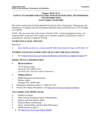
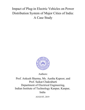
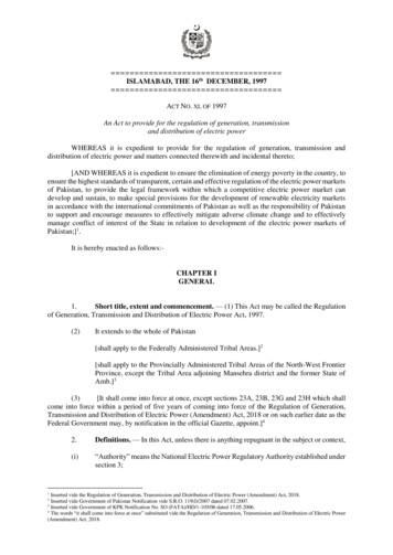
Kiran Kolhe et alElectric Power Generation System from Speed Breaker by using Rack and Pinion Mechanismwere running on roads in 2002, which increased to72.7 million vehicles in the year 2004. The growth rateof vehicles in India has increased almost 10 percentannually during the last decade (R. Gupta, et al, 2013),(A.K. Sharma, et al, 2012). The increasing traffic andnumber of speed breakers these days emphasize onconditions to manufacture an innovative device whichcan use the energy of vehicles that is wasted on speedbreakers to some profitable work. We can capture thiskinetic energy at the speed breaker so that it can serveour purpose of electricity generation. An electromechanical unit is fixed under the speed breaker whichis explained in the paper. This unit convertsreciprocating motion into rotary motion. The rotationalpower (i.e. mechanical energy) is converted into theelectrical energy by using gear arrangement and agenerator which generates electricity. And thisgenerated electricity can be used in variousapplications.Averagely, when we consider speed breaker heightof 10 cm (S. Priyadarshani, 15 June 2007), and a 1500kg vehicle passing over the speed breaker, ampleamount of power can be generated. This amounts to24.52 W of power for 1 minute. Thus in an hour, 1.47kW of power approx. is generated which will add up to35.31 kW of power per day. This is equivalent to alarge value and is sufficient enough to run 4-6 streetlights a day. It contributes greatly to the generation ofelectricity and thus it will release the load onpowerplants and because of this greater equivalents ofelectricity will be available for industries leading toprogressive development of the nation.2. HistoryElectricity generation began somewhere around 100years ago, and before this idea was known houses werelit with help of kerosene lamps, iceboxes were used tocool the food, and rooms were warmed by stoves usingeither coal or wood for burning. Direct current (DC)electricity was used in arc lights for outdoor lighting.Nikola Tesla pioneered the generation, transmission,and use of alternating current (AC) electricity, in thelate-1800s, which could be transmitted over muchgreater distances compared to direct current.The first ever generation of electricity was done byusing Faraday’s dynamo in the 1800’s. Almost 200years later, it was found that we are still using the samebasic principles to generate electricity, only on a muchlarger scale. The standard conventional fossil fuels arethe key sources for power generation, but there is afear of these conventional fossil fuels getting exhaustedeventually by the next few decades. Hence it hasbecome mandatory for us to search on some newalternative sources for power generation, which wouldlast for a longer duration (N.V. Bhavsar, et al, 2015).Therefore, it is necessary & important that we dependon non-conventional energy sources for powergeneration. While moving, vehicles possess kineticenergy and some of the kinetic energy is wasted. Thiskinetic energy which is already being wasted cantherefore be utilized to produce power by using aspecial arrangement called “electro-mechanical unit”.Electricity production from a speed breaker is a newconcept that is undergoing research.Figure 2.1 Power generation from speed breaker3. The idea of electricity from speed breakerThe number of vehicles on road is increasing rapidlyand if some of the Kinetic energy of these vehicles isconverted into rotational motion of generator then aconsiderable amount of electricity can be produced. Atpresent, there is shortage of electricity leading toenergy crisis.Can electricity be generated using speed breakers?Could this idea be beneficial in any case? The answer is,yes, of course. This idea will be advantageous; forgenerating electricity for the traffic signals, streetlights,and then for many other purposes. The Transcalm roadbump which is a speed breaker was invented by aBritish engineer Graham Heeks, who dreamed up theconcept after examining squeezable children's toys (W.Knight, 21 Aug 2001). Generally, when vehicle is inmotion it produces various forms of energy like the“Heat Energy”, which is produced due to frictionbetween tyres of vehicle’s wheel and the road i.e. roughsurface, or when vehicle traveling with a high speedstrikes the wind. This heat energy produced is alwayslost in environment and remains unused which is justthe wastage of energy abundantly available around us.In this paper, one such method is referred andexplained in order to generate “Electrical Energy”. Thismethod uses the principle of “Kinetic Energy to ElectricEnergy conversion”.Figure 3.1 Speed breaker1152 International Journal of Current Engineering and Technology, Vol.7, No.3 (June 2017)
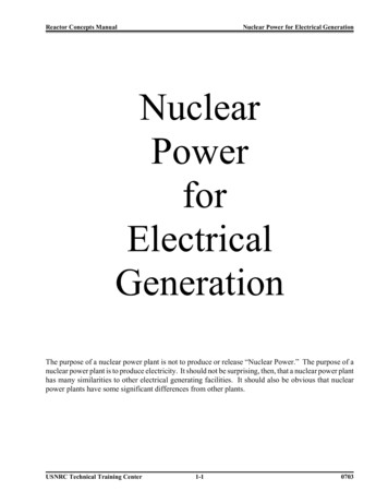
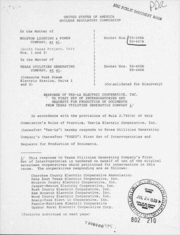
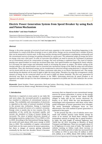
Kiran Kolhe et alElectric Power Generation System from Speed Breaker by using Rack and Pinion MechanismNow, one question can rise on the use of speedbreakers, that, why only speed breakers should beused? And why not rough roads and uneven surfaceprove beneficial for this? The answer to this is simple,that rough surfaces are not that apt to providesufficient torque which is necessary in order toproduce electricity by rack and pinion method (F. N. C.Anyaegbunam, 2015).mechanical energy to electrical energy. The kineticenergy of the vehicle which is wasted at the speedbreaker is converted to mechanical energy of the unitbelow speed breaker by the rack and pinionmechanism. This mechanical energy is later convertedto electrical energy by a generator.4. Energies involved in this methodThe mechanism used in the assembly is rack andpinion mechanism. It converts reciprocating motioninto rotary motion. Here, the rack is the elementproducing reciprocating motion and pinion rotates dueto this reciprocating motion. The rack is displacedvertically due to the weight of the vehicle passing onthe speed breaker and thus it reciprocates (M.Ramadan, et al, 2015). As the rack reciprocates, it turnsthe pinion to rotate. The rack is the flat part which hasteeth, while the pinion is a gear.Three types of energies are taking part in thisconversion in order to generate electricity.4.1 Kinetic EnergyEnergy possessed by a body due to virtue of its motionis called as Kinetic energy. The kinetic energy of anobject of mass m traveling at a speed v is ½ mv2 . Thekinetic energy of an object is directly proportional tothe square of its speed. The kinetic energy of an objectis completely described by magnitude alone (scalarquantity).4.2 Mechanical EnergyMechanical energy is the energy associated with boththe motion and position of an object. Objects possessmechanical energy when they are in motion or if theyare at a zero potential energy position. An object gainsenergy, when some work has been done on it. Theenergy gained by the objects on which, work is done, isknown as mechanical energy.4.3 Electrical EnergyWhen energy is stored in charged particles which arein an electric field, that energy is known to be electricalenergy. The regions or areas which form an envelopearound these charged particles are called as electricfields. The electric fields are a result of chargedparticles, and they exert force on other chargedparticles causing them to move in the electric field.5. Mechanism usedAdvantages of rack and pinion mechanism This assembly gives good mounting convenience.Gear losses are maximum up to 5%.Approximate efficiency of rack and pinionmechanism is about 95%.6. Equipment required for the system6.1 Rack and pinionA rack and pinion comprises of a pair of gears whichconvert reciprocating motion into rotational motion orvice versa. The rack is the flat part which has teeth,while the pinion is a gear (A. Kaur, et al, 2013).Figure 6.1Rack and pinion6.2 Ball bearingsFigure 6.2 Ball bearingFigure 4.1 Energy ConversionThe basic energy conversion taking place is first fromkinetic energy to mechanical energy and then fromA ball bearing is a type of rolling-element thatuses balls to maintain the separation betweenthe bearing races. It permits relative motion betweenthe surfaces which are in contact while carrying loads.The relative motion between the components causes1153 International Journal of Current Engineering and Technology, Vol.7, No.3 (June 2017)
Kiran Kolhe et alElectric Power Generation System from Speed Breaker by using Rack and Pinion Mechanismthe balls to roll with little sliding. The ball bearing isused to reduce friction and transmit the motioneffectively.6.3 Spur GearA gear is a rotating element which has teeth that meshwith some other part having teeth in order to transmittorque. It is a positive power transmission device withdefinite velocity ratio (P. Vishnoi, et al, 2014). It shouldhave high resistance for wear and tear, and highcapacity to absorb shock.Figure 6.5 Pawl and ratchet6.6 FlywheelThe primary or main function of the flywheel is toreduce the fluctuations in speed. It is known as anenergy accumulator. The flywheel proves to be of greathelp as, it absorbs extra energy and stores it whendemand is less, and releases this stored energy whenthe demand increases (F. Najuib, et al, 2014).Figure 6.3 Spur gear6.4 Sprocket and Chain driveIt is a profiled wheel with teeth that can mesh witha chain, or other perforated material. Sprocket isgenerally a wheel upon which radial projectionsengage a chain passing over it. Chain drive is used toconnect the sprockets in order to transmit power (C. B.Prakash, et al, 2014). It is distinguished from a gear,that sprockets are never meshed together directly.Figure 6.6 Flywheel6.7 ShaftFigure 6.4 Sprocket6.5 Pawl and RatchetA mechanical device which allows motion in only onedirection is called ratchet. The ratchet is a gear whichhas teeth and it is circular in shape. The pawl is aspring loaded hook type structure which is pivoted atone end and the other end makes contact with theteeth of the ratchet. It fits in to the space between theteeth of the ratchet and thus prevents the reversemotion by restricting the backward movement of theratchet. The pawl is raised when the ratchet rotates inforward motion, and when the rotation of ratchetstops, the pawl rests between the teeth of the ratchet.Thus a constrained one direction motion is achieved byusing pawl and ratchet.It is a rotating element, which is used for transmissionof power from one element to another element. Itsupports rotating elements like gears and flywheels.The shaft is mounted on bearings in order to providefree rotation of shaft about its own axis (M. Sailaja, etal, 2015). A shaft is expected to have high torsionalrigidity and lateral rigidity.Figure 6.7 Shaft6.8 SpringSpring is an element which possess elasticity and itsfunction is to expand and contract to recover its1154 International Journal of Current Engineering and Technology, Vol.7, No.3 (June 2017)
Kiran Kolhe et alElectric Power Generation System from Speed Breaker by using Rack and Pinion Mechanismoriginal shape when it is loaded or unloaded. Itchanges its shape according to the load applied. Itabsorbs energy either due to shocks or due tovibrations. Springs are usually made out of hardenedsteel. Small springs can be wound from pre-hardenedstock, while larger ones are made from annealed steeland hardened after fabrication (S. Srivastava, et al,2011).Figure 6.9 Generator6.10 BatteryIt is a device which stores energy generated from thegenerator. The energy is stored in the form of chemicalenergy in the battery (N. Kumar, et al, 2016). Thisenergy can be used as and when it is required.7. WorkingFigure 6.8 SpringThe working of the electro-mechanical unit isfacilitated by considering 3 systems-6.9 Generator or DynamoIt is a device which converts mechanical energy intoelectrical energy. For this energy conversion, thegenerator or dynamo uses rotating coils of wire andmagnetic fields.1) Damper system2) Motion Conversion system3) Energy Conversion system.Figure 7.1 Constructional details of Electro-mechanical unit7.1 Damper systemDamper system is required to support the speedbreakers. The speed breaker is made up of materialslike recycled plastic, vulcanized rubber etc. The speedbreaker designs may be: the “Sleeping Policeman”,which has a rounded top; the “Speed Cushion”, which isa raised square in the middle of a lane; and the “SpeedTable”, which is a wide flat-topped speed breaker (S.English, 11 Nov 2005). Damper system consists of aspring which is required to push the speed breakerupwards when it is acted upon by the weight of thevehicle downwards (Ankita, et al, 2013). They are alsorequired to absorb the shocks produced when thevehicles pass over the speed breakers.7.2 Motion conversion systemThis system is required to convert the basic verticalreciprocating motion of the damper system into rotarymotion of the shafts. For this a rack & pinionmechanism is used. The vehicle load acted upon the1155 International Journal of Current Engineering and Technology, Vol.7, No.3 (June 2017)
Kiran Kolhe et alElectric Power Generation System from Speed Breaker by using Rack and Pinion Mechanismspeed breaker is transmitted to rack and pinionarrangements. This vertical motion is converted torotary motion and transmitted to a sprocketarrangement. The sprocket arrangement consists oftwo sprockets – one larger diameter and the other ofsmaller diameter. The axis of the pinion is coupled tothe larger sprocket. The pinion and the larger sprocketare mounted on the same shaft. Now the larger andsmaller sprocket are connected with each otherthrough a chain drive. Smaller sprocket is mounted onanother shaft. The smaller sprocket consists of a pawland a ratchet which avoids the rotation in reversedirection of the shaft on which smaller sprocket ismounted. Thus, the shaft on which smaller sprocket ismounted rotates in one direction only. i.e. it rotatesonly when the rack moves downward due to load ofvehicle. When the rack moves upward to return to itsinitial position, the rotation of shaft is avoided by thepawl and ratchet. This is similar to the operation of abicycle wheel (A. K. Singh, et al, 2013). As the sprocketarrangement is connected by a chain drive the speedavailable at larger sprocket is characteristicallymultiplied at the smaller sprocket (A. Mishra, et al,2013). Thus a larger speed is obtained. The axis of thesmaller sprocket is coupled to a gear arrangementwhich consists of two gears with different dimensions.The gear wheel with the larger diameter is coupled tothe axis of the smaller sprocket and these two aremounted on the same shaft. The speed that has beenincreased at the smaller sprocket wheel is handed tothis gear wheel of larger diameter. The smaller gear ismeshed to the larger gear. Therefore, as the larger gearrotates, it increases the speed of the smaller gear andmultiplies it to more intensity. Though the speed due tothe rotational motion achieved at the larger sprocketwheel is less, the final speed achieved is high, as thepower is transmitted to gears. The smaller gear iscoupled to the dynamo or generator. Between thesmaller sprocket and the larger gear, a flywheel ismounted on the same shaft to adjust the fluctuation inthe energy (H. Singh, et al, 2016). Flywheel also makesthe energy consumption uniform so that the shafts willrotate with certain speed consistently. Thusmechanical energy is available at the output of motionconversion system.relatively the armature is also turned around the shaftaxis. The armature has 2 rings, each connected to 1 endof the armature. These rings rotate with the armature.To these rings, brushes are connected. This assembly isknown as slip ring & brush assembly. The brushes arestationary part of this assembly and are generallymade of carbon. The output of the brushes is connectedto outer circuit for measuring current. As the armaturerotates with current induced in its arms, the brushestransmit this current to the outer circuit.The field magnets are designed such that they areconcave at the inner side and entirely cylindrical inshape. The reason for this is, it enables the magnets togenerate radial magnetic field. As the armature rotatesin the radial magnetic field about an axis perpendicularto the magnetic field, an EMF (electro-magnetic force)is generated which induces current in the armaturearms. The EMF is generated as the armature cuts themagnetic field flux, already present due to the magnets(K. P. Singh, et al, 2014). Now, as the armaturecontinuously rotates, the direction of the currentinduced in its arms changes constantly. As a result ofthis we get an alternating current, which has sinusoidalnature characteristic. Thus electric current is achievedand it is stored in storage sources such as a battery andused whenever required.7.3 Energy conversion systemWeight of cars vary from 1200 kg -2000 kg (for anaverage car) approx. The power generation may begreater for heavy vehicles such as trucks, buses etc.The speed breaker height is generally up to 10 cm(Eastleigh Borough Council, 27 Sept 2006). Ifaveragely, 1500 kg weight and 10 cm height isconsidered then approx.In this system the mechanical energy available at thesmaller gear (i.e. at the output of the motionconversion system) is converted to electrical energy bymeans of a dynamo or generator. The smaller gear iscoupled to the dynamo or generator. The conversionwill be proportional to traffic density (G. R. Prabu, et al,2015). A Dynamo or Generator consists of a stationarystructure, called the stator, which provides a constantmagnetic field, and a winding called, the armature,which rotates within that field. The armature is a softiron core on which a copper coil of turns is mountedand it is connected to the shaft of the smaller gear. Soas the smaller gear rotates, the shaft also rotates andFigure 7.2 Working of the unit (A. Mishra, et al, 2013)8. Power Calculations(1 N-m 1 Joule)1 N-m/s 1 WattPower Work done /sWeight of car (W) mgm mass of car1156 International Journal of Current Engineering and Technology, Vol.7, No.3 (June 2017)
Kiran Kolhe et alElectric Power Generation System from Speed Breaker by using Rack and Pinion Mechanismg gravitational acceleration 9.81 m/W 1500 * 9.81W 14715 NWork done Weight * displacement (i.e. height ofbreaker) 14715 * 0.10 1471.5 N-m 1471.5/60 24.52 WWork done 24.52 WattsPower 24.52 Watts for 1 minuteFor 60 minutes (1 hour) 24.52 * 60 1471.5 WFor 24 hours (1 day) 1471.5 * 24 35316 WApprox. 35.31 kW of power generated per day.9. Block DiagramFigure 9.1 Block diagram of system10. Advantages1) We can have annual electricity generation with thehelp of this method without depending on otherfactors.2) Power generation takes place reasonably and byusing non-conventional energy sources which willhelp to preserve the conventional energy sourcesfor our adjacent future demand.3) There is no usage of any fossil fuel hence electricityis generated by renewable means.4) Pollution less energy generation (A. S. Fawade,2015).5) Simple construction, mature technology and easymaintenance.6) This method requires less measure of floor areaand also the traffic is not obstructed.7) It is economical and not difficult to install.8) This method is promising due to its good efficiencyand energy recovery criteria.11. Applications1) Street Lights can be provided with electricitygenerated by this method.2) Traffic Signals can be run by using the electricitygenerated by this method.3) Sign boards on the roads can be lit with the help ofthis method.4) Boards near the bus-stops can be highlighted byusing this method generated electricity.5) This method can also be used on the check postson highways.ConclusionThis paper introduces another innovative method ofgreen power generation in order to contribute towardsthe development of the country by enriching it withutilization of available resources in more usefulmanner. Due to population explosion, the currentpower generation has become insufficient to fulfil ourrequirements. In the upcoming days, as demand ofelectricity is increasing rapidly, it will prove a greatboon to the country and also to the world, since it willsave a lot of electricity of powerplants which is wastedin illuminating the street light. This research can beused to develop our country by enhancing more andmore utilization of its sources in more appropriate andproficient manner. The development of a country isdirectly proportional to the way in which it uses powersupply sufficiently and efficiently. Now is the need ofan hour when these types of inventive ideas should bebrought into practice. This idea not only provides analternative, but also adds to the economy of thecountry. Development of every country is thedevelopment of the world.Future ScopeAccording to statistics, in 2009, in India, the averageannual domestic electricity consumption per capita inurban areas was 288 kWh and in rural areas was 96kWh approximately (A. P. Rao, et al, 2014). While theworldwide average annual consumption per capita was2600 kWh and 6200 kWh in European Union (J.Goldemberg, et al, 1985). At present India is facingmajor shortage of capacity to produce electricity.India is regarded as a developing nation and hencedue to growing population, the needs will increasewhich will indirectly increase the consumption ofelectrical energy (A. K. N. Reddy, et al, 1994).Electricity can be produced from wide range ofresources but however, their cost is commercially highand hence the concept proposed in this paper would beuseful in future for electricity production as the cost forelectricity production is comparatively less.Suitable at parking of malls as well as multiplexes.Also can be used for toll booths, signals, etc. Such speedbreakers can also be designed for heavy duty vehicles,thus increasing input torque and ultimately output ofgenerator. Various government departments can takeinitiative in implementing these power humps on alarge scale. This has a huge scope everywhere,provided the resources are channelled well. Thus theelectricity consumed in running the street lights can besaved with the help of these method and this savedelectricity can be given to remote villages in Indiawhich already do not receive electricity (V.Aswathaman, et al, 2011).1157 International Journal of Current Engineering and Technology, Vol.7, No.3 (June 2017)
Kiran Kolhe et alElectric Power Generation System from Speed Breaker by using Rack and Pinion MechanismReferencesN. Fatima, J. Mustafa (2012), Production of electricity by themethod of road power generation, Int. J. advances inElectrical and Electronics Engineering, 1: 9-14.S.A. Jalihal, K. Ravinder, T.S. Reddy (2005), Trafficcharacteristics of India, Proc. Eastern Asia Society forTransportation studies, 5: 1009-1024.R. Gupta, S. Sharma, S. Gaykawad (2013), A revolutionarytechnique of power generation through speed breakerpower generators, Int. J. Engineering. Research andTechnology, 2(8): 1879-1883.A.K. Sharma, O. Trivedi, U. Amberiya, et al. (2012)Development of speed breaker device for generation ofcompressed air on highways in remote areas. Int. J. RecentResearch and Review, 1: 11-15.S. Priyadarshani, (15 June 2007), Generating electricity fromspeed breakers. Down to Earth.N.V. Bhavsar, V. A. Shah, (2015), Electricity generation byspeed breaker using spur gear mechanism, Int. J. Researchin Applied Science and Engineering Technology, 3(4): 11641169.W. Knight, (21 Aug 2001), Smart speed bumps reward ?id dn1178.F. N. C. Anyaegbunam, (2015), Electric power generation byspeed breaker generators, IOSR J. Engineering, 5(9): 17-21.M. Ramadan, M. Khaled, et al. (2015), Using speed bump forpower generation, In: The 7th International Conference onApplied Energy, Energy procedia, pp.867-872.A. Kaur, S. K. Singh, Rajneesh, et al. (2013), Power generationusing speed breaker with auto street light, Int. J.Engineering Science and Innovative Technology, 2(2): 488491.P. Vishnoi, P. Agrawal, (2014), Power generation by kineticenergy of speed breaker, MIT Int. J. Electrical andInstrumentation Engineering ,4(2): 90-93.C. B. Prakash, A. V. R. Rao, P. Srinuvas, (2014), Road powergeneration by speed breaker, Int. J. Engineering Trends andTechnology, 11(2): 75-78.F. Najuib, N. Gupta, P. Rawat, et al. (2014), Energy efficientpower generation using speed breaker with auto streetlights, Int. J. Engineering Research and ManagementTechnology, 1(1): 223-228.M. Sailaja, M. R. Roy, S. P. Kumar, (2015), Design of rack andpinion mechanism for power generation at speed breakers,Int. J. Engineering Trends and Technology, 22(8): 356-362.S. Srivastava, A. Asthana, (2011), Produce electricity by theuse of speed breakers, J. Engineering Research and Studies,2(1): 163-165.N. Kumar, P. Saini, M. Kumar, (2016), Automatic road lightcontroller through electricity generation from speedbreaker, Int. J. Engineering Technology Science andResearch, 3(4): 17-25.S. English, (11 Nov 2005), Smart road hump will smooth /0,,2-1867157,00.html.Ankita, M. Bala, (2013), Power generation from speedbreaker, Int. J. Advance Research in Science and Engineering,2(2).A. K. Singh, D. Singh, M. Kumar, et al. (2013), Generation ofelectricity through speed breaker mechanism, Int. J.Innovations in Engineering and Techno
Electricity production from a speed breaker is a new concept that is undergoing research. Figure 2.1 Power generation from speed breaker 3. The idea of electricity from speed breaker The number of vehicles on road is increasing rapidly . method uses the principle