Transcription
PLANT START-UP AND SHUT-DOWNSEQUENCE DESCRIPTIONENGSOFT LabSeoul, Koreawww.engsoft.co.kr
PLANT START-UP AND SHUT-DOWN SEQUENCEENGSOFT LabCONTENTS1.0GENERAL2.0PLANT START-UP SEQUENCE2.1Plant Start-up Preparation Sequence2.2Plant Base Utility Start-up Sequence2.3Plant Auxiliary System Start-up Sequence2.4Power Block Start-up Sequence3.0PLANT SHUT-DOWN SEQUENCE4.0ABBREVIATIONAttachment APOWER BLOCK AUTOMATIC START-UP SEQUENCEAttachment BPOWER BLOCK AUTOMATIC SHUT-DOWN SEQUENCEAttachment B.1 ONE GT/HRSG SHUT-DOWN SEQUENCE WITH STG CONTINUEDOPERATIONAttachment B.2 LAST GTG/HRSG AND STG SHUT-DOWN SEQUENCEAttachment B.3 BOTH GT/HRSG’S AND STG SHUT-DOWN SEQUENCEAttachment CEMERGENCY SHUT-DOWN SEQUENCE
PLANT START-UP AND SHUT-DOWN SEQUENCE1.0ENGSOFT LabGENERALThis document is to describe the overall start-up and shut-down sequence of a CombinedCycle Power Plant.The detailed start-up and shut-down sequence of equipment and unitsystems shall be described in the relevant documents of the equipment and the unitsystems.Only details described herein are the automatic start-up and shut-down sequences ofpower block which are not described elsewhere.The power block consists of GTG’s, HRSG’s and STG.Except the power block, all auxiliary systems including system filling, electrical and I&Csystem are started up or shut down step by step manually by the operators in control roomand local as required.The operation of each auxiliary system is automated as describedin relevant system description.This sequence assumes that the plant fire fighting system is always in operation.
ENGSOFT LabPLANT START-UP AND SHUT-DOWN SEQUENCE2.0Plant Start-up SEQUENCE2.1Plant Start-up Preparation Sequence2.1.1Energizing of Electrical and I&C SystemEnergizing of plant electrical, instrumentation and control system shall be performed byreceiving start-up electricity from the grid.Electricity export system to the grid shall be made as ready, too.Details of energizing sequence and making electricity export system ready shall bedescribed in separate documents.2.1.2Check of Plant Battery Limit(BL) ConditionsThe following conditions should be satisfied for start-up.Equipment/SystemAt BLsystemoffuelConditionTag No.Remarksgas Main shut-off valveopenPressure LowAt BL of raw. water Pressure Lowsystem2.1.3Start-up of Cycle Make-up SystemPermissive : Demi. water storage tank level Low - LowIf filling is required, cycle make-up system shall be started first.If filling is not required, the start-up of cycle make-up system shall be performed after theoperation of compressed air system.Operation of cycle make-up system shall be confirmed by the following conditions.
ENGSOFT LabPLANT START-UP AND SHUT-DOWN SEQUENCEEquipment/SystemConditionTag No.Demi. water storage Waterinlettankvalve “Open”One cycle make-up - Runningpump- Dischargepressure Low2.1.4RemarksIf instrument air isnotavailable,manual operationis required.FillingPermissive : Cycle make-up system in OperationIf the liquid level of tanks, vessels and basins is lower than those required, filling shall beperformed to the levels for start-up.Details of filling sequence shall be described in the operation manual of equipment andthe system description of auxiliary systems.The filling shall be confirmed by the following conditions.Equipment/SystemConditionFuel Gas Supply LineGas pressureinnormalpressureHRSG HP drumsLevel Startup levelHRSG IPdrumsLevel Startup levelHRSG LPdrumsLevel Startup levelCondenser hotwellLevel LowCirculatingwaterpump pitClosed cooling waterhead tankRaw water storagetankDemi. water storageLevel LowLevel LowLevel LowLevel LowTag No.RemarksSubstitutenitrogen filled fuelgas line withnatural gasStart-uplevelshall be definedbyHRSGsupplier.Start-uplevelshall be definedbyHRSGsupplier.Start-uplevelshall be definedbyHRSGsupplier.
ENGSOFT LabPLANT START-UP AND SHUT-DOWN SEQUENCEEquipment/SystemConditiontankDiesel oil day tank ofdieselenginefirewater pumpDiesel oil day tank ofemergencydieselengine generatorMain cycle chemicalsolution tanksSodium hypochloritetankCondenservacuumpump separatorsGTG lube oil tanksSTG lube oil tankLevel LowLevel LowAux boiler drumLevel LowH2, CO2, N2Storage SystemTag No.RemarksLevel LowLocal panelLevel LowLocal panelLevel LowLocal panelLevel LowLevel LowGas Gas pressureinnormalpressureLocal panelLocal GaugeBefore filling, it is required to assure whether all manual drain valves for emptying ofsystem lines are closed and all instrumentation root valves are manipulated for filling.Vent valves are closed manually after confirmation of filling by local operators.2.1.5Waste Water Transfer SystemAll sump pumps shall be READY and set to AUTO mode at local control panel.It should be also confirmed that the waste water treatment plant is ready to operate andreceive the waste water from the power plant.2.2Plant Base Utility Start-up Sequence2.2.1Start-up of Aux. Circulating Water SystemAn aux. circulating water system shall be started in order to supply cooling water toclosed cooling water system, especially for supplying cooling water to air compressorsand seal water coolers of vacuum pumps. In order to prevent the aux. circulating waterpump from operation under its minimum flow, the water flow circuit to closed coolingwater heat exchangers shall be secured.
ENGSOFT LabPLANT START-UP AND SHUT-DOWN SEQUENCEOperation of aux. circulating water system shall be confirmed by the following conditions.Prior to aux CWP running, pump chamber traveling screen system shall be ready tooperate in order to screen seawater.Equipment/SystemConditionTag No.RemarksAux circulating water - Level Low Lowpump chamber waterlevelOne aux. circulating - Runningwater pump- Discharge pressure LowCirculatingwater Operatingchemical feed system2.2.2Start-up of Closed Cooling Water SystemAfter start-up and operation of aux. circulating water system, the closed cooling watersystem shall be started to supply cooling water to equipment coolers including aircompressors.Operation of closed cooling water system shall be confirmed by the following conditions.Equipment/SystemOne closedwater pumpConditionTag No.Remarkscooling - Running- Discharge pressure LowOne closed cooling - Dischargewater heat exchangertemperature Low- Dischargetemperature HighClosed cooling water Level control valve inhead tankAUTO mode2.2.3Start-up of Compressed Air SystemPermissive : Closed cooling water system in OperationAfter start-up and operation of closed cooling water system, the compressed air systemshall be started to supply compressed air to the plant, especially instrument air to controlvalves.
ENGSOFT LabPLANT START-UP AND SHUT-DOWN SEQUENCEOperation of compressed air system shall be confirmed by the following conditions.Equipment/SystemOne air compressorConditionTag No.RemarksAUTO modeCompressed air system - Commonheaderpressure Low- No system commonalarm2.2.4Start-up of Fuel Gas SystemPermissive : Natural gas pressure at BL LowCompressed air system in OperationNatural gas system shall be started to supply fuel to GTG’s.Operation of natural gas system shall be confirmed by the following conditions.1) Fuel Gas Side Lined-UpEquipment/SystemShut-off valve for mainsupply headerVent valve for mainsupply headerShut-off valve for unitsupplyVent valve for unitsupplyFuel gas particulatefilterConditionValve OpenValve CloseValve OpenValve CloseFuel gas scrubberUpper Drain pot level HighLower Drain pot level HighUpper HTR Drain potlevel HighLower HTR Drain potlevel HighDrain pot level HighFuel gas drain tankDrain pot level HighFuel gas heater2) Heating Water (IP Feedwater) Side Lined-UpTag No.Remarks
PLANT START-UP AND SHUT-DOWN SEQUENCEENGSOFT LabStep 1Prior to the initiation of a GT/HRSG startup, the feedwater supply isolation valve,heater inlet isolation valve, heater outlet isolation valve and feedwater return isolationvalve are closed. The temperature control valve is held closed by an interlock. Thefeedwater supply line vent valve and feedwater return line vent valve are open toallow any gas leak to feedwater system to vent out. The temperature set point is 48deg.C and ramp rate is 1.1.deg.C/sec of set point after IP economizer is in serviceNoteBefore GT/HRSG startup, heater inlet isolation valve and heater outlet isolationvalve shall be closed until the feedwater temperature is cooled down. If thesevalves are open without enough cooled down, hot feedwater will be flashed andgas detection bridle pipe located at heater top needs to be vented before plantstart-up.Step 2Once the feedwater system (boiler feedwater pump) is in operation, heater inletisolation valve is closed. Feedwater supply isolation valve is opened initiatingfeedwater flow through the vent line to purge the vent line through feedwater supplyline vent valv. After a short second delay, the feedwater supply line vent valve isclosed and then the heater inlet isolation valve and Heater outlet isolation valve areopen to initiate water to the heater. Purging will occur via flow through the Heateroutlet isolation valve and the feedwater return line vent valve. After short seconddelay after the heater inlet isolation valve and the heater outlet isolation valve areopen, the feedwater return line vent valve will be closed and the feedwater returnisolation valve is opened aligning the vent and isolation valves for normal operation.Step 3Flow is established by automatic opening of the fuel gas temperature control valve toa pre-set minimum flow control position once the following conditions are satisfiedAND maintained.- Feedwater is operation AND- Condensate System is operating AND- The valves are lined upNoteIn no case the fuel gas temperature exceeds the preset 48 oC other than Fuel
ENGSOFT LabPLANT START-UP AND SHUT-DOWN SEQUENCEGas Performance Heater Permissive Signal pick up. Start up with feedwaterhigher than 48 oC [120 oF], the fuel gas temperature control valve shall beclosed before gas turbine startup.Equipment/SystemFeedwatersupplyisolation valveFeedwater supply linevent valveHeater inlet isolationvalveHeater outlet isolationvalveFeedwater return linevent valveFeedwaterreturnisolation valveFuel gas temperaturecontrol valveValve openFuel gas heaterHTR upper channelbridle level LowHTR lower channelbridle level LowLevel LowFeedwater bridle pipe2.2.5ConditionTag No.RemarksValve closedValve openValve openValve closedValve openMinimum OpenPosition whenfeedwater temp 48 oCActivation ofTemperaturecontrol deferredtill Feedwatersystem,Condenstatesystem inoperation.Operation of Auxiliary Steam SystemThe operation of the auxiliary steam system is required to supply steam to the plantsteam users, such as condenser/HRSG sparging system, STG warming system, STGgland seal steam system, etc.Normal steam source of auxilairy steam system is the cold reheat steam system of theUnit and an auxiliary boiler has been provided for cold start-up of entire power plant.The auxiliary steam system is common for both Units. Therefore, if one Unit operating,the auxiliary steam for the start-up of the other Unit can be supplied from the Unitoperating.If the first Unit was being started up, start-up of auxiliary boiler is required for supplying
ENGSOFT LabPLANT START-UP AND SHUT-DOWN SEQUENCEsteam to the auxiliary steam system.Operation of the auxiliary steam system shall be confirmed by the following nTag No.Remarkssteam - Pressure Low- TemperatureLow The start-up sequences and start-up ready list of auxiliary boiler shall be described in aseparate document to be prepared by auxiliary boiler supplier.Before the start-up of the auxiliary boiler, the following permissives should be safisfied.Permissive:Closed cooling water system in OperationFuel gas supply system in operationCycle make-up system in OperationCompressed Air system in Operation2.3Plant Auxiliary System Start-up SequenceAfter closed cooling water system and compressed air system are in operation, thefollowing systems shall be started regardless of the order of description below, as long asthe permissives are satisfied.2.3.1Start-up of Circulating Water SystemCirculating water system shall be started in order to supply cooling water to condenser.Operation of circulating water system shall be confirmed by the following conditions.Prior to CWP running, pump chamber traveling screen system shall be ready to operatein order to screen seawater.Equipment/SystemConditionCirculating water pump - Level Low Lowchamber water levelOne circulating water - RunningTag No.Remarks
ENGSOFT LabPLANT START-UP AND SHUT-DOWN SEQUENCEEquipment/SystemConditionTag No.Remarkspump- Discharge press.not Low( Low)- Discharge MOV“Open”- Inlet valve OpenCondenser- Outlet valve“Open”Circulatingwater Operatingchemical feed systemCondensercleaning systemtube IntermittentlyoperatingDebris Filter2.3.2IntermittentlyoperatingStart-up of Condensate SystemPermissive : Compressed air system in OperationDemin. water system in OperationCondensate system shall be started for ;-providing gland steam condenser with cooling water,-providing seal water to water seal valves and-supplying the condenser condensate to HRSG.Operation of condensate system shall be confirmed by the following onLevel Lowcondensate - Running- Min. flowvalve inmodecontrolAUTO- Condenserlevelcontrol valve inAUTO modeTag No.Remarks
ENGSOFT LabPLANT START-UP AND SHUT-DOWN SEQUENCEEquipment/SystemConditionTag No.Remarks- Condensate dumpcontrol valve inAUTO mode- Discharge pressure LowOperation of condensate system does not mean the condenser is in operation.Condenser in operation shall be confirmed during the automatic start-up sequence ofpower block.2.3.3Start-up of Feed Water SystemPermissive : Compressed air system in OperationCondensate system in OperationClosed cooling water system in OperationHRSG LP drum level NOT LowFW Pumps lube oil system in serviceFeed water system shall be started to supply feed water for HRSG’s.Operation of feed water system shall be confirmed by the following conditions.Equipment/SystemFeed water pumpsHPfeedpresssureConditionTag No.RemarksRunningwater Disch. Press. LowHP Eco. InletPreesure (HPsteam system byHRSG Vendor)IP feed water presssure Disch. Press. Low2.3.4Bypass System(HP and HRH) Ready for OperationThe bypass system shall be ready for operation according to the procedure prepared bythe bypass valve supplier.The bypass system shall not be activated at this stage and activated when the condenserpressure is low enough to accept bypass steam during the automatic start-up sequence
ENGSOFT LabPLANT START-UP AND SHUT-DOWN SEQUENCEof power block.2.4Power Block Start-up SequenceThe power block equipment consisting of GTG’s, HRSG’s and STG, shall be placed onreadiness for automatic start-up.2.4.1GTG on Barring Gear OperationPermissive : Compressed air system in OperationClosed cooling water system in OperationGTG auxiliary systems, such as lubricating oil system, hydraulic oil system, gas fuelsystem, inlet air system, etc., shall be started and/or put into ready-to-start status, andthen finally GTG shall be placed on barring gear operation for start-up.The start-up sequences of GTG auxiliary systems and the start-up ready list of GTG’sshall be described in a separate document to be prepared by GTG supplier.2.4.2HRSG on Ready to StartPermissive : Compressed air system in OperationClosed cooling water system in OperationCondensate system in operationFeed water system in operationHRSG’s shall be placed on ready to start according to the procedure prepared by HRSGsupplier.Readiness of HRSG’s for start-up shall be confirmed by the following conditions, whichshall be finally confirmed by HRSG supplier.Equipment/SystemHP drumCondition- Level Startup level- Drumlevelcontrol valveinAUTOmodeTag No.Remarks
ENGSOFT LabPLANT START-UP AND SHUT-DOWN SEQUENCEEquipment/SystemHP desuperheaterIP drumLP drumReheater desuperheaterMain stack damperLP economizerConditionTag No.RemarksDSHeatertemp.controlvalve in AUTOmode- Level Startup level- Drumlevelcontrol valveinAUTOmode- Level Startup level- Drumlevelcontrol valveinAUTOmodeDSHtemperaturecontrol valve inAUTO modeOpenBypass valve inAUTO modeRecirculationvalve in AUTOmodeA recirculationpump runningPumpdischargepressure LowFor the cold start-up of HRSG’s(when HP drum water temperature is less than 100 oC),perform the following actions.-Ensure that all condensed steam has been evacuated from the superheaters andreheaters before starting up the HRSG’s by opening the superheater and reheaterdrains.-If HRSG’s have been standing full of water for some time, it is recommended toopen the drains on the economizers and evaporators for a short period (until flow isverified) to drain any accumulated solids.
PLANT START-UP AND SHUT-DOWN SEQUENCEENGSOFT LabHRSG valves shall be lined up in accordance with HRSG manufacturer’s list.2.4.3STG on Turning Gear OperationPermissive : Compressed air system in OperationCirculating Water system in OperationClosed cooling water system in OperationSTG auxiliary systems, such as lubricating oil system, control oil system, gland steamsystem, drainage system, exhaust spray water system, etc., shall be started and/or putinto ready-to-start status, and then finally STG shall be placed on turning gear operationfor start-up.The start-up sequences of STG auxiliary systems and the start-up ready list of STG shallbe described in a separate document to be prepared by STG supplier.(After long term shut down, minimum 3 hrs operation of turning shall be required beforeSTG running)2.4.4Condenser Vacuum-upPermissive : STG on turning gear OperationCondensate system in OperationCirculating water system in OperationClosed cooling water system in OperationAuxiliary steam system in OperationCompressed air system in OperationCondenser vacuum-up shall be performed, when the warming-up of STG or the start-upof power block is required.For condenser vacuum-up, the sealing of STG gland shouldbe performed in advance.The gland steam temperature requirements of STG are as below.- STG Very Hot or Hot Start: 350 oC to 540 oC- STG Warm Start: 210 oC to 390 oC- STG Cold Start: 150 oC to 260 oC
ENGSOFT LabPLANT START-UP AND SHUT-DOWN SEQUENCEWhereas, the auxiliary steam temperature varies as below depending on the steamsource.- Supply from cold reheat steam system: 320 oC through 370 oC- Supply from auxiliary boiler: 260 oC constantCondenser vacuum-up procedure shall be performed in the following sequence. Eachstep shall be initated by the operator at DCS.Step A.Depending on STG Start-up mode, the electric heater shall be activated or deactivatedas below, in order to comply with STG steam temperature requirements.- STG Very Hot or Hot Start: Activated- STG Warm or Cold Start: DeactivatedStep B.The operator initiates at DCS the opening of the steam seal auxiliary feed isolationdrain valve in order to drain condensate and make steam supreheated before beingsupplied to STG gland steam system.If the auxiliary steam temperature is lower than 400 oC for STG Very Hot or Hot Start,the electric superheater shall increase the steam temperature to 400 oC.If STG is in Cold Start mode and the auxiliary steam system is being supplied from thecold reheat steam system of the other Unit, the auxiliary steam temperature is notproper for STG gland sealing and the start-up of auxiliary boiler is required for supplyof colder steam.In this case, the axiliary boiler shall be started and then theauxiliary steam supply isolation valve of the cold reheat system of the other Unit shallbe close. The auxiliary steam supply isolation valve of the cold reheat system of theother Unit shall be open when the auiliary boiler is shut down.Step C.When the auxiliary steam temperature to STG gland steam system satisfies the STGtemperature requirement after the opening of the steam seal auxiliary feed isolationdrain valve, DCS shall take 5 minute time delay and flag to the operator “ST GLANDSEAL STEAM READY”.
PLANT START-UP AND SHUT-DOWN SEQUENCEENGSOFT LabAfter the flagging of “ST GLAND SEAL STEAM READY” by DCS, the operator initiatesthe sending of “ST GLAND SEAL START” signal to STG TCS after confirming thesteam temperature for himself.Step D.After receiving the “ST GLAND SEAL START” signal from DCS, STG TCS shall openthe steam seal auxiliary feed valve isolation valve and then send a signal of “STSTEAM SEAL AUX FEED VALVE OPEN” to DCS.After receiving the signal of “ST STEAM SEAL AUX FEED VALVE OPEN” from STGTCS, DCS shall close the steam seal auxiliary feed isolation drain valve.Step E.After receiving the “ST GLAND SEAL START” signal from DCS, STG TCS shall peformthe gland sealing of ST.When STG gland steam system is operating, STG TCS shall send a signal of “SEALSTEAM COMPLETE” to DCS and then DCS shall flag “SEAL STEAM COMPLETE” tothe operator.Step F.After flagging “SEAL STEAM COMPLETE ” on DCS, the operator initiates the start-upof Condenser Air Removal System.2.4.5ST Pre-WarmingPermissive : STG on turning gear OperationCondensate system in OperationClosed cooling water system in OperationAuxiliary steam system in OperationCondenser vacuum 7.5 inch Hg abs.(0.25 kg/cm2 abs.)HRSG cold reheat isolation valves(MOV-1329A/B & MOV-2329A/B) CloseIf STG HP shell metal temperature is less than 150 oC(Ambient Cold Start), STG TCSshall send a digital signal of “ST PRE-WARMING REQUIRED CONDITION” to DCS.(Hold) for the operator’s acknowledgement of STG Pre-warming Start
ENGSOFT LabPLANT START-UP AND SHUT-DOWN SEQUENCEIf the digital signal of “ST PRE-WARMING REQUIRED CONDITION” was received, DCSshall send a digital signal of “ST PRE-WARMING START” to STG TCS, and then STGTCS shall start STG HP turbine pre-warming sequence including holding time afterconfirming condenser vacuum and auxiliary steam conditions.After completion of STG pre-warming, STG TCS will send a digital signal of “ST PREWAMING COMPLETED” to DCS.As long as STG is in “ST PRE-WARMING REQUIRED CONDITION”, the start-up of STGwill not be permitted by STG TCS.2.4.6Automatic Start-up of Power BlockWhen the plant is ready for start-up of power block by completing the start-up sequencesabove, the automatic start-up of the power block shall be initiated by operator, and theplant shall be started and loaded to the target load automatically.Since the start-up of power block to target load is performed automatically, it isrecommended for operators to check with time the readiness of plant for start-up beforethe automatic start-up of power block is initiated.The automatic start-up sequence of power block has been attached as Attachment A.Start-up sequencing of power block can be performed in either of full-automatic and semiautomatic.In the sequence description following, the step with “(Go/Hold)” mark stands for theselection point for “Go” or “Hold” by operator.performed at any time before the step is passed.The “Go” or “Hold” selection may beIf all “Go/Hold” are selected as “Go”before APS starts, the power block starts in full-automatic mode.
PLANT START-UP AND SHUT-DOWN SEQUENCE3.0ENGSOFT LabPlant Shut-down SEQUENCEThe plant shut-down sequence is reverse order of start-up sequence.After shut-down of power block, the shut-down of auxiliary systems depends on.Whennext start-up is expected soon, the auxiliary systems shall remain in operation, whereasthe auxiliary systems shall be shut down and placed on preservation status when longtime shut-down is expected.Therefore, the plant shut-down sequence has not been described here except the powerblock automatic shut-down sequence.3.1Automatic Shut-down of Power BlockThe shut-down of power block shall be performed automatically by initiation of operators.There are three kinds of automatic power block shut-down as below.-One GT/HRSG shut-down with STG continued operation-Last GT/HRSG and STG shut-down.-Both GT/HRSG’S and STG Shut-downThe automatic shut-down sequence of power block has been attached as Attachment B.3.2Emergency Shut-downThe emergency shut-down sequence on trip of GTG, HRSG and STG, has been attachedas Attachment C.
PLANT START-UP AND SHUT-DOWN SEQUENCE4.0(End)ABBREVIATIONAPSAutomatic Plant Start-up SystemAPCAutomatic Plant Control SystemSTG TCSSTG Turbine Control SystemGTG TCPGTG Turbine Control PanelENGSOFT Lab
ENGSOFT LabPLANT START-UP AND SHUT-DOWN SEQUENCEAttachment A POWER BLOCK AUTOMATIC START-UP SEQUENCEStep 10OPERATOR INITIATIONStep 10-1Selection of LEAD/LAG/IDLE Mode of Each GTG/HRSG TrainOperator selects on DCS manually LEAD/LAG/IDLE mode of each GTG/HRSG Train.LEAD GTG/HRSG starts first and LAG GTG/HRSG starts later.IDLE GTG/HRSG train shall notstart.In this description, it is assumed that GTG1/HRSG1 is selected as LEAD GTG/HRSG andGTG2/HRSG2 is selected as LAG GTG/HRSG.In case that one GTG/HRSG train is started by APS while the other GTG/HRSG train is operatingwith STG, the GTG/HRSG train to start is selected as LAG and the GTG/HRSG train operating isselected as IDLE.If the case, APS begins at Step 100.APS IN and APS OUT buttons in addition to APS START button are provided.Operator should select APS IN button and then APS START button.To start APS,To stop APS, Operatorshould select APS OUT button.APS stops in the following three cases.-Operator pushes APS OUT button.-Trip occurs.-APS is finished.If Operator pushes APS OUT button or trip occurs, plant shall maintain the operating conditions atthe time of ASP stops.When APS is finished, APC takes over plant control.Step 10-2 Target Load InputTarget load(CCPP MW output) to be achieved when APS is finished is input by Operator.WhenOperator inputs APS target load, the target load of Automatic Generation Control(AGC) is alsochanged to the APS target load automatically, so that CCPP output is synchronized to AGC targetload automatically when APS is finished.
PLANT START-UP AND SHUT-DOWN SEQUENCEENGSOFT LabStep 10-3 Valve Line-upAPS checks valve line-up and puts automatic valves in AUTO or CAS(casecade) modes accordingto their own start-up control logic.included in the line-up check.The valves in steam/water cycle and fuel gas system are
ENGSOFT LabPLANT START-UP AND SHUT-DOWN SEQUENCEStep 20GTG1 (LEAD) START-UP TO TEMPERATURE MATCHING LOADStep 20-1Start-up Mode Selection of STG1 and HRSG120-1-A) Start-up mode of STG shall be decided by STG TCS and send to DCS as one of digitalsignals.STG TCS selects its start-up mode based on steam turbine metal temperature(ST Tm)as below.(Refer to STG Supplier’s Document)zST Cold Start: 150 ST Tm 220 oCzST Warm Start: 220 ST Tm 370 oCzST Hot Start: 370 ST Tm 520 oCzST Very Hot Start: 520 ST Tm20-1-B) Start-up mode of HRSG1 shall be decided by DCS for each HRSG1 pressure level (HP, IPand LP) based on the pressure of respective drum as below.The logic diagrams to be preparedby HRSG supplier shall describe the selection sequence of HRSG Start-up Mode.(unit : kg/cm2g)Hot StartWarm Start Cold StartzHP: 63.8 3.51 3.51zIP: 7.67 0.707 0.707zLP 3.51 0.707 0.707Step 20-2GTG1 Ready to StartDCS sends “RESET” and “CUSTOMER PERMISSIVE TO START” digital signal to GTG1 TCP,when HRSG1, STG1 and all BOP equipment are ready to start and all GTG1 trip/runbackconditions are checked as clear.GTG1 TCP uses this signal as one of its own start-up permissives.When all permissives ofGTG1 are met and auxiliary checks are satisfied, GTG1 TCP sends to DCS a digital signal of“READY TO START”.(Go/Hold) for the operator’s acknowledgement of GTG1 firing.Step 20-3GTG1 FSNLAfter receiving the signal of “READY TO START” from GTG1 TCP, DCS deactivates the plant loadcontrol signal to GTG1 so that GTG1 load control by APS is not affected by APC.
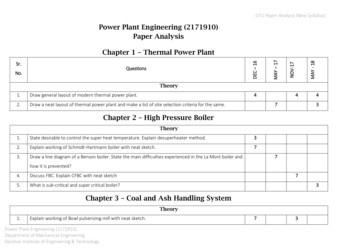
ENGSOFT LabPLANT START-UP AND SHUT-DOWN SEQUENCEThen DCS sends “START” signal to GTG1 TCP so that GTG1 starts.When GTG1 reaches Full Speed No Load(FSNL), GTG1 TCP shall send an signal of "FULLSPEED NO LOAD”, which shall be used as the indication of “GTG1 on FSNL” in DCS.Step 20-4GTG1 Minimum LoadUpon GTG1 on FSNL, GTG1 is synchronized manually by the operator or automatically by GTG1TCP depending on the operator’s selection of synchronization type.After synchronization, GTG1is automatically loaded to its minimum load by GTG1 TCP.When GTG1 reaches the minimum load, GTG1 TCP shall send an signal of "MINIMUM LOAD”,which shall be used as the indication of “GTG1 on Minimum Load” in DCS.Step 20-5GTG1 Temperature MatchingOnce GTG1 has been reached at Minimum Load, GTG1 shall be put into temperature matching.Temperature matching can be initiated between the Minimum Load and 50 % of GTG base load.Temperature matching of GTG is performed as below.If the target temperature for temperature matching is lower than the GTG exhaust gas temperatureat the load before temperature matching initiation, GTG load is decreased to the Minumum Load ifGTG load is higher than the Minimum Load, and then GTG IGV is opened to the angle having thetarget temperature.If the target temperature for temperature matching is higher than the GTG exhaust gastemperature at the load before temperature matching initiation, GTG load is increased to a loadhaving the target temperature with its IGV at the mimimu angle.GTG exhaust gas temperature profile for cold start-up is as below.
ENGSOFT LabPLANT START-UP AND SHUT-DOWN SEQUENCETemp, oC7005 Maximum Temp.5 6004 5001 2 3 400Minimum Temp.3000255075100GT Load, %GTG Exhaust Gas Temperature Profile for Cold Start-up1 : From FSNL to the Minimum Load (the minimum IGV) 2 : Temperature matching for Cold Start (IGV open to an angle higher than the minum IGV) 3 : Temperature matching OFF (IGV close to the minimum angle) 4 : Normal operation with the minimum IGV 5 : Normal operation with the IGV angle higher than the minimum IGV
ENGSOFT LabPLANT START-UP AND SHUT-DOWN SEQUENCEThe temperature matching shall b
PLANT START-UP AND SHUT-DOWN SEQUENCE ENGSOFT Lab 2.1.4 Filling Permissive : Cycle make-up system in Operation If the liquid level of tanks, vessels and basins is lower than those required, filling shall be performed to the levels for start-up. Details of filling sequence shall be described in the operation manual of equipment and