Transcription
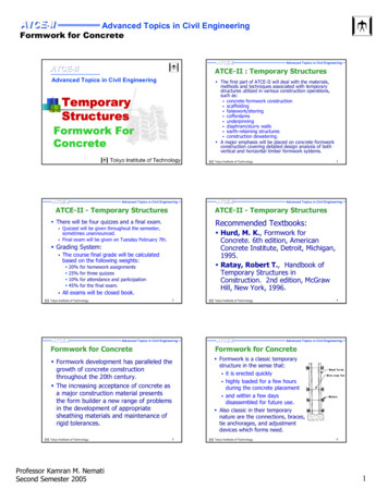
CM 420TEMPORARY STRUCTURESLesson 4: CofferdamsOverviewA cofferdam is a temporary structure designed to keep water and/or soil out of the excavationin which a bridge pier or other structure is built. When construction must take place belowthe water level, a cofferdam is built to give workers a dry work environment. Sheet piling isdriven around the work site, seal concrete is placed into the bottom to prevent water fromseeping in from underneath the sheet piling, and the water is pumped out. The word"cofferdam" comes from "coffer" meaning box, in other words a dam in the shape of a box.This lesson covers structural cofferdams as temporary installation, explaining in step-by-stepdetail proper and safe methods and materials to be used. There are different types ofcofferdam, some are used to support excavation operation and some are enclosed type boxplaced in the water. The focus of this lesson is on the latter type.Lesson ObjectivesBy the end of this lesson you will be able to: describe cofferdams and when they are used on construction projects; describe the forces on cofferdams explain design considerations; recognize the importance of sealing the bottom of cofferdamsReading AssignmentClass notesOptional reading: Ratay, Chapter 7 "Cofferdams".
CM 420 – TEMPORARY STRUCTURESLESSON 4: COFFERDAMS1. INTRODUCTION Cofferdams are temporary enclosures to keep out water and soil so as to permitdewatering and construction of the permanent facility (structure) in the dry. A cofferdam involves the interaction of the structure, soil, and water. The loads imposedinclude the hydrostatic forces of the water, as well as the dynamic forces due to currentsand waves. In construction of cofferdams maintaining close tolerances is difficult since cofferdamsare usually constructed offshore and sometimes under severe weather conditions. Underthese circumstances, significant deformations of cofferdam elements may happen duringthe course of construction, and therefore it may be necessary to deviate from the designdimensions in order to complete the project according to plan. The loads imposed on the cofferdam structure by construction equipment and operationsmust be considered, both during installation of the cofferdam and during construction ofthe structure itself. Removal of the cofferdam must be planned and executed with the same degree of care asits installation, on a stage-by-stage basis. The effect of the removal on the permanentstructure must also be considered. For this reason, sheet piles extending below thepermanent structure are often cut off and left in place, since their removal may damage thefoundation soils adjacent to the structure. In cofferdam construction, safety is a paramount concern, since workers will be exposedto the hazard of flooding and collapse. Safety requires that every cofferdam and every part thereof shall be of suitable design andconstruction, of suitable and sound material and of sufficient strength and capacity for thepurpose for which it is used, proper construction, verification that the structure is beingconstructed as planned, monitoring the behavior of the cofferdam and surrounding area,provision of adequate access, light and ventilation, and attention to safe practices on thepart of all workers and supervisors, and shall be properly maintained.Types of cofferdam:1. Braced: It is formed from a single wall of sheet piling which is driven into the ground toform a “box” around the excavation site. The box is then braced on the inside and theinterior is dewatered. It is primarily used for bridge piers in shallow water (30 - 35 ftdepth)2. Earth-Type: It is the simplest type of cofferdam. It consists of an earth bank with a claycore or vertical sheet piling enclosing the excavation. It is used for low-level waters withlow velocity and easily scoured by water rising over the top.3. Timber Crib: Constructed on land and floated into place. Lower portion of each cell ismatched with contour of river bed. It uses rock ballast and soil to decrease seepage andsink into place, also known as “Gravity Dam”. It usually consists of 12’x12’ cells and isused in rapid currents or on rocky river beds. It must be properly designed to resist lateralforces such as tipping / overturning and sliding.4. Double-Walled Sheet Pile: They are double wall cofferdams comprising two parallelrows of sheet piles driven into the ground and connected together by a system of tie rodsat one or more levels. The space between the walls is generally filled with granularmaterial such as sand, gravel or broken rock.Page 1 of 13
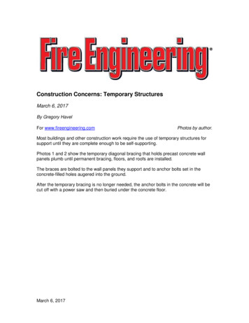
CM 420 – TEMPORARY STRUCTURESLESSON 4: COFFERDAMS5. Cellular: Cellular cofferdams are used only in those circumstances where the excavationsize precludes the use of cross-excavation bracing. In this case, the cofferdam must bestable by virtue of its own resistance to lateral forces.Advantages of CofferdamPerforming work over water has always been more difficult and costly than performing thesame work on land. And when the work is performed below water, the difficulties and costdifference can increase geometrically with the depth at which the work is performed. The keyto performing marine construction work efficiently is to minimize work over water, andperform as much of the work as possible on land. Below some of the advantages ofcofferdams are listed: Allow excavation and construction of structures in otherwise poor environment Provides safe environment to work Contractors typically have design responsibility Steel sheet piles are easily installed and removed Materials can typically be reused on other projectsInstallationThe success of any piling scheme requires satisfactory completion of the following stages.1. Competent site investigation, sampling and relevant testing to build up an informedpicture of the task.2. Adequate design of all the stages of the construction.3. Setting out and installation of the piles.As with all site operations the relevant legislation and guidance on matters pertaining to safetymust be strictly adhered to. Items needed for installation are pile driving hammer (vibratoryor impact), crane of sufficient size, steel sheet piles are typically used, H-piles and/or wideflange beams for wales and stringers. In many cases barges may be required for efficientinstallation of cofferdams.2. TYPES OF IMPOSED LOADSA typical cofferdam will experience several loading conditions as it is being build and duringthe various construction stages. The significant forces are hydrostatic pressure, forces due tosoil loads, water current forces, wave forces, ice forces, seismic loads and accidental loads. Inorder to over come the displaced water buoyancy, the tremie seal thickness is about equal tothe dewatered depth. Figure below shows a typical cofferdam schematic.Page 2 of 13
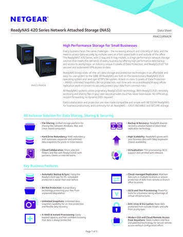
CM 420 – TEMPORARY STRUCTURESLESSON 4: COFFERDAMSFigure 0 – Typical cofferdam schematicHydrostatic pressureThe maximum probable height outside the cofferdam during construction and thewater height inside the cofferdam during various stages of construction need to beconsidered. These result in the net design pressure shown in Fig. 1 below:Figure 1 - Hydrostatic forces on partially dewatered cofferdamPage 3 of 13
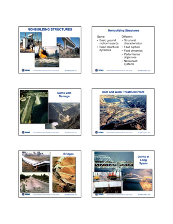
CM 420 – TEMPORARY STRUCTURESLESSON 4: COFFERDAMSForces due to Soil LoadsThe soils impose forces, both locally on the wall of the cofferdam and globally uponthe structure as a whole. These forces are additive to the hydrostatic forces.Local forces are a major component of the lateral force on sheet-pile walls, causingbending in the sheets, bending in the wales, and axial compression in the struts (seeFig. 2).Figure 2 - Soil force in typicalweak muds or claysCurrent Forces on StructureWith a typical cofferdam, the current force consists not only the force acting on thenormal projection of the cofferdam but also on the drag force acting along the sides.With flat sheet piles, the latter may be relatively small, whereas with z-piles it may besubstantial, since the current will be forming eddies behind each indentation of profile,as shown in Fig. 3.Figure 3 – Current flow along sheet pilesWave forcesWaves acting on a cofferdam are usually the result of local winds acting over arestricted fetch and hence are of short wavelength and limited to height. However, insome cases the cofferdam should have at least three feet of freeboard or higher abovethe design high water elevation than the maximum expected wave height. Waveforces will be significant factor in large bays and lakes where the fetch is severalmiles. Passing boats and ships, especially in a restricted waterway, can also producewaves. The force generated by waves is asymmetrical and must be carried to theground through the sheet piling in shear and bending. The waler system must bedesigned to transmit the wave forces to the sheet piles.Ice forcesThese are of two types: the force exerted by the expansion of a closed-in solidlyfrozen-over area of water surface (static ice force) and the forces exerted by themoving ice on breakup (dynamic ice force). As an example, for static ice force, avalue of 4000 lb/ft2 has been used on cofferdams and structures on the great Lakes,whereas the value due to dynamic ice force on a cofferdam-type structure are oftentaken at 12,000 to 14,000 lb/ft2 of contact area.Page 4 of 13
CM 420 – TEMPORARY STRUCTURESLESSON 4: COFFERDAMSSeismic LoadsThese have not been normally considered in design of temporary structures in the past.For very large, important, and deep cofferdams in highly seismically active areas,seismic evaluation should be performed.Accidental loadsThese are the loads usually caused by construction equipment working alongside thecofferdam and impacting on it under the action of waves.3. Scour:Scour of the river bottom or seafloor along the cofferdam may take place owing to rivercurrents, tidal currents, or wave-induced currents. Some of the most serious anddisastrous cases have occurred when these currents have acted concurrently.A very practical method of preventing scour is to deposit a blanket of crushed rock orheavy gravel around the cofferdam, either before or immediately after the cofferdam sheetpiles are set. A more sophisticated method is to lay a mattress of filter fabric, covering itwith rock to hold it in place.4. COFFERDAM COMPONENTS: Sheet pilingSheet piling is a manufactured construction product with a mechanical connection“interlock” at both ends of the section. These mechanical connections interlock withone another to form a continuous wall of sheeting. Sheet pile applications are typicallydesigned to create a rigid barrier for earth and water, while resisting the lateral pressuresof those bending forces. The shape or geometry of a section lends to the structuralstrength. In addition, the soil in which the section is driven has numerous mechanicalproperties that can affect the performance. Bracing frame Concrete sealThe typical cofferdam, such as a bridge pier, consists of sheet piles set around a bracingframe and driven into the soil sufficiently far to develop vertical and lateral support and tocut off the flow of soil and, in some cases the flow of water (Fig. 4).Figure 4 – Typical cofferdam without seal or pilePage 5 of 13
CM 420 – TEMPORARY STRUCTURESLESSON 4: COFFERDAMSThe structure inside may be founded directly on rock or firm soil or may require pilefoundations. In the latter case, these generally extend well below the cofferdam.Inside excavation is usually done using clam shell buckets. In order to dewater thecofferdam, the bottom must be stable and able to resist hydrostatic uplift. Placement of anunderwater concrete seal course is the fastest and most common method.An underwater concrete seal course may then be placed prior to dewatering in order toseal off the water, resist its pressure, and also to act as a slab to brace against the inwardmovement of the sheet piles in order to mobilize their resistance to uplift under thehydrostatic pressure (Fig. 5)Figure 5 – Typical cofferdam (with seal)5. COFFERDAM CONSTRUCTION SEQUENCE:For a typical cofferdam, such as for a bridge pier, the construction procedure follow thelisted pattern.1. Pre-dredge to remove soil or soft sediments and level the area of the cofferdam (Fig.6a).2. Drive temporary support piles (Fig. 6b).3. Temporarily erect bracing frame on the support piles (Fig. 6b).4. Set steel sheet piles, starting at all four corners and meeting at the center of each side(Fig. 6c).5. Drive sheet piles to grade (Fig. 6c).6. Block between bracing frame and sheets, and provide ties for sheet piles at the top asnecessary (Fig. 6c).7. Excavate inside the grade or slightly below grade, while leaving the cofferdam full ofwater (Fig. 7a).8. Drive bearing piles (Fig. 7b).9. Place rock fill as a leveling and support course (Fig. 7b).10. Place tremie concrete seal (Fig. 7c).Page 6 of 13
CM 420 – TEMPORARY STRUCTURESLESSON 4: COFFERDAMSFigure 6 – Cofferdam construction sequence (I). (a) Pre-dredge. (b) Drive support piles; setprefabricated bracing frame and hang from support piles. (c) Set sheet piles; drive sheet piles;block and tie sheet piles to top wale.11. Check blocking between bracing and sheets (Fig. 8a).12. Dewater (Fig. 8a).13. Construct new structure (Fig. 8a and b).Page 7 of 13
CM 420 – TEMPORARY STRUCTURESLESSON 4: COFFERDAMSFigure 7 – Cofferdam construction sequence (II). (a) Excavate initial and final grade. (b)Drive bearing piles in place. (c) Place tremie concrete.14. Flood cofferdam (Fig. 8b).15. Remove sheet piles (Fig. 8c).16. Remove bracing (Fig. 8c).17. Backfill (Fig. 8c).Page 8 of 13
CM 420 – TEMPORARY STRUCTURESLESSON 4: COFFERDAMSFigure 8 – Cofferdam construction sequence (III). (a) Check blocking; dewater; constructfooting block; block between footing and sheet piles. (b) Remove lower bracing; constructpier pedestal; construct pier shaft. (c) Flood cofferdam; pull sheets; remove bracing; backfill.Placement of the concrete seal is by tremi
These have not been normally considered in design of temporary structures in the past. For very large, important, and deep cofferdams in highly seismically active areas, seismic evaluation should be performed. Accidental loads These are the loads usually caused by construction equipment working alongside the cofferdam and impacting on it under the action of waves. 3. Scour: Scour of the river .File Size: 1MBPage Count: 22