Transcription
Earg FM.qxd15/9/044:54 PMPage iTHE MICROPHONE BOOKSecond edition
Earg FM.qxd14/9/043:11 PMPage ii
Earg FM.qxd14/9/043:11 PMPage iiiTHE MICROPHONEBOOKSecond editionJohn EargleAMSTERDAM BOSTON HEIDELBERG LONDON NEW YORK OXFORDPARIS SAN DIEGO SAN FRANCISCO SINGAPORE SYDNEY TOKYOFocal Press is an imprint of Elsevier
Earg FM.qxd14/9/043:11 PMPage ivFocal PressAn imprint of ElsevierLinacre House, Jordan Hill, Oxford OX2 8DP30 Corporate Drive, Burlington MA 01803First published 2005Copyright 2005, John Eargle. All rights reservedThe right of John Eargle to be identified as the author of this workhas been asserted in accordance with the Copyright, Designs andPatents Act 1988No part of this publication may be reproduced in any material form (includingphotocopying or storing in any medium by electronic means and whetheror not transiently or incidentally to some other use of this publication) withoutthe written permission of the copyright holder except in accordance with theprovisions of the Copyright, Designs and Patents Act 1988 or under the terms ofa licence issued by the Copyright Licensing Agency Ltd, 90 Tottenham Court Road,London, England W1T 4LP. Applications for the copyright holder’s writtenpermission to reproduce any part of this publication should be addressedto the publisherPermissions may be sought directly from Elsevier’s Science and Technology RightsDepartment in Oxford, UK: phone: ( 44) (0) 1865 843830; fax: ( 44) (0) 1865 853333;e-mail: permissions@elsevier.co.uk. You may also complete your request on-line via theElsevier homepage (www.elsevier.com), by selecting ‘Customer Support’and then ‘Obtaining Permissions’British Library Cataloguing in Publication DataA catalogue record for this book is available from the British LibraryLibrary of Congress Cataloguing in Publication DataA catalogue record for this book is available from the Library of CongressISBN02405 1961 2For information on all Focal Press publications visit our website at:www.focalpress.comTypeset by Newgen Imaging Systems (P) Ltd, Chennai, IndiaPrinted and bound in the United StatesWorking together to growlibraries in developing countrieswww.elsevier.com www.bookaid.org www.sabre.org
Earg FM.qxd15/9/044:55 PMPage vCONTENTSPreface to the First EditionPreface to the Second EditionSymbols Used in This Bookviiixx1 A Short History of the Microphone12 Basic Sound Transmission and Operational Forces onMicrophones73 The Pressure Microphone224 The Pressure Gradient Microphone505 First-Order Directional Microphones6 High Directionality Microphones66917 Microphone Measurements, Standards, andSpecifications1058 Electrical Considerations and Electronic Interface9 Overview of Wireless Microphone Technology10 Microphone Accessories15211 Basic Stereophonic Recording Techniques12 Stereo Microphones16618413 Classical Stereo Recording Techniques andPractice19414 Studio Recording Techniques21715 Surround Sound Microphone Technology16 Surround Recording Case Studies271243117142
Earg FM.qxd14/9/043:11 PMPage viviContents17 A Survey of Microphones in Broadcast andCommunications29018 Fundamentals of Speech and MusicReinforcement30119 Overview of Microphone Arrays and AdaptiveSystems32220Care and Maintenance of Microphones21Classic Microphones: The Author’s ViewReferences and BibliographyIndex373367334338
Earg FM.qxd14/9/043:11 PMPage viiPREFACE TO THE FIRST EDITIONMost sound engineers will agree that the microphone is the mostimportant element in any audio chain, and certainly the dazzling arrayof current models, including many that are half-a-century old, attests tothat fact. My love affair with the microphone began when I was in myteens and got my hands on a home-type disc recorder. Its crystal microphone was primitive, but I was nonetheless hooked. The sound bug hadbitten me, and, years of music schooling not withstanding, it wasinevitable that I would one day end up a recording engineer.About thirty years ago I began teaching recording technology at various summer educational programs, notably those at the Eastman Schoolof Music and later at the Aspen Music Festival and Peabody Conservatory.I made an effort at that time to learn the fundamentals of microphone performance and basic design parameters, and my Microphone Handbook,published in 1981, was a big step forward in producing a text for some ofthe earliest collegiate programs in recording technology. This new bookfrom Focal Press presents the technology in greater depth and detail and,equally important, expands on contemporary usage and applications.The Microphone Book is organized so that both advanced studentsin engineering and design and young people targeting a career in audiocan learn from it. Chapter 1 presents a short history of the microphone.While Chapters 2 through 6 present some mathematically intensivematerial, their clear graphics will be understandable to those with littletechnical background. Chapters 7 through 10 deal with practical matterssuch as standards, the microphone-studio electronic interface, and alltypes of accessories.Chapters 11 through 17 cover the major applications areas, withemphasis on the creative aspects of music recording in stereo and surround sound, broadcast/communications, and speech/music reinforcement. Chapter 18 presents an overview of advanced development inmicrophone arrays, and Chapter 19 presents helpful hints on microphonemaintenance and checkout. The book ends with a comprehensive microphone bibliography and index.
Earg FM.qxd14/9/04viii3:11 PMPage viiiPreface to the First EditionI owe much to Leo Beranek’s masterful 1954 Acoustics text, A. E.Robertson’s little known work, Microphones, which was written for theBBC in 1951, as well as the American Institute of Physics’ Handbook ofCondenser Microphones. As always, Harry Olson’s books came to myaid with their encyclopedic coverage of everything audio.Beyond these four major sources, any writer on microphones mustrely on technical journals and on-going discussions with both users andmanufacturers in the field. I would like to single out for special thanksthe following persons for their extended technical dialogue: NorbertSobol (AKG Acoustics), Jörg Wuttke (Schoeps GmbH), David Josephson(Josephson Engineering), Keishi Imanaga (Sanken Microphones), and inearlier days Steve Temmer and Hugh Allen of Gotham Audio. Numerousmanufacturers have given permission for the use of photographs anddrawings, and they are credited with each usage in the book.John EargleApril 2001
Earg FM.qxd14/9/043:11 PMPage ixPREFACE TO THESECOND EDITIONThe second edition of The Microphone Book follows the same broadsubject outline as the first edition. Most of the fundamental chaptershave been updated to reflect new models and electronic technology,while those chapters dealing with applications have been significantlybroadened in their coverage.The rapid growth of surround sound technology merits a new chapter of its own, dealing not only with traditional techniques but also withlate developments in virtual imaging and the creation of imaging thatconveys parallax in the holographic sense.Likewise, the chapter on microphone arrays has been expanded toinclude discussions of adaptive systems as they involve communicationsand useful data reduction in music applications.Finally, at the suggestion of many, a chapter on classic microphoneshas been included. Gathering information on nearly thirty models was afar more difficult task than one would ever have thought, and it wastruly a labor of love.John EargleLos Angeles, June 2004
Earg FM.qxd14/9/043:11 PMPage xSYMBOLS USED IN THIS BOOKaAAFc CddBdB(A)dBuDCDIEe(t)fHFHzIIi(t)I0jkkg KLFLPLRLNmMFmm mradius of diaphragm (mm); acceleration (m/s2)ampere (unit of electrical current)audio frequencyspeed of sound (334 m/s at normal temperature)temperature (degrees celsius)distance (m)relative level (decibel)A-weighted sound pressure levelsignal voltage level (re 0.775 volt rms)critical distance (m)directivity index (dB)voltage (volt dc)signal voltage (volt rms)frequency in hertz (s–1)high frequencyfrequency (hertz, cycles per second)acoustical intensity (W/m2)dc electrical current, ampere (Q/s)signal current (ampere rms)mechanical moment of inertia (kg m2)complex algebraic operator, equal to 1wave number (2 / )mass, kilogram (SI base unit)temperature (degrees kelvin, SI base unit)low frequencysound pressure level (dB re 20 Pa)reverberant sound pressure level (dB re 20 Pa)noise sound pressure level (dB re 20 Pa)meter (SI base unit)mid frequencymillimeter (m 10–3)micrometer or micron (m 10–6)
Earg FM.qxd14/9/043:11 PMPage xiSymbols Used in This BookMMDNp; p(t)PQQrR, RRERFRHsSTT, tTT60T0torru; u(t)U, U(t)x(t)XVZ 00cmximicrophone system sensitivity, mV/Pacapacitor microphone base diaphragm sensitivity, V/Paforce, newton (kg, m/s2)rms sound pressure (N/m2)power (watt)electrical charge (coulombs, SI base unit)directivity factordistance from sound source (m)electrical resistance (ohm)room constant (m3 or ft3)random efficiency of microphone (also REE)radio frequencyrelative humidity (%)second (SI base unit)surface area (m2)torque (N m)time (s)magnetic flux density (tesla)reverberation time (seconds)diaphragm tension (newton/meter)atmospheric pressure; equal to mm of mercury (mmHg), or133.322 Pa (Note: 760 torr is equal to normal atmosphericpressure at 0 C)air particle rms velocity (m/s)air volume rms velocity (m3/s)air particle displacement (m/s)mechanical, acoustical, or electrical reactance ( )electrical voltage (voltage or potential)mechanical, acoustical or electrical resistance ( )average absorption coefficient (dimensionless)wavelength of sound in air (m)phase, phase shift (degrees or radians)dependent variable in polar coordinatesdensity of air (1.18 kg/m3)specific acoustical impedance of air (415 SI rayls)angle (degrees or radians), independent variable in polarcoordinates2 f (angular frequency in radians/s)surface mass density (kg/m2)
Earg FM.qxd14/9/043:11 PMPage xii
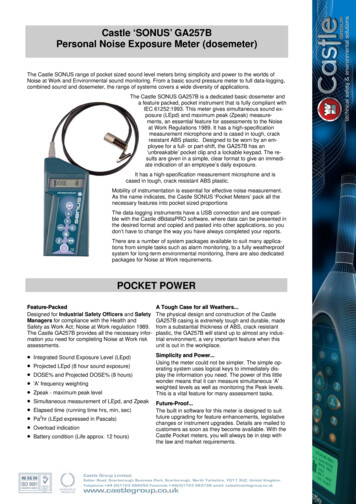
Earg 01.qxd14/9/042:34 PMPage 1CHAPTER1A SHORT HISTORY OF THEMICROPHONEINTRODUCTIONThe microphone pervades our daily lives through the sound we hear onradio, television and recordings, paging in public spaces, and of coursein two-way communications via telephone. In this chapter we will touchupon some of the highlights of more than 125 years of microphonedevelopment, observing in particular how most of the first 50 of theseyears were without the benefits of electronic amplification. The requirements of telephony, radio broadcast, general communications, andrecording are also discussed, leading to some conjecture on futurerequirements.THE EARLY YEARSAs children, many of us were fascinated with strings stretched betweenthe ends of a pair of tin cans or wax paper cups, with their ability to convey speech over a limited distance. This was a purely mechano-acousticalarrangement in which vibrations generated at one end were transmittedalong the string to actuate vibrations at the other end.In 1876, Alexander Graham Bell received US patent 174,465 on thescheme shown in Figure 1–1. Here, the mechanical string was, in a sense,replaced by a wire that conducted electrical direct current, with audiosignals generated and received via a moving armature transmitter and itsassociated receiver. Like the mechanical version, the system was reciprocal. Transmission was possible in either direction; however, thepatent also illustrates the acoustical advantage of a horn to increase thedriving pressure at the sending end and a complementary inverted hornto reinforce output pressure at the ear at the receiving end. Bell’s furtherexperiments with the transmitting device resulted in the liquid transmitter,
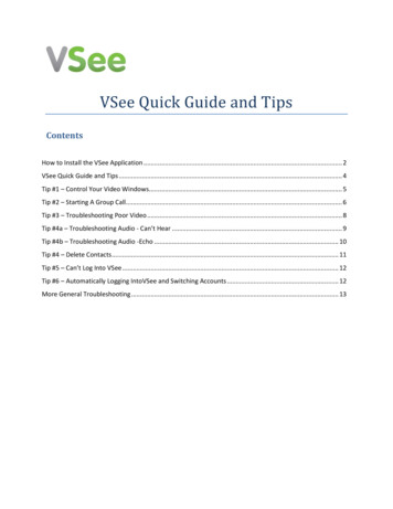
Earg 01.qxd14/9/042:34 PMPage 22THE MICROPHONE BOOKFIGURE 1–1The beginnings oftelephony; Bell’soriginal patent.FIGURE 1–2Bell’s liquid transmitterexhibited at thePhiladelphia CentennialExposition of 1876.shown in Figure 1–2, which was demonstrated at the PhiladelphiaCentennial Exposition of 1876. Here, the variable contact principleprovided a more effective method of electrical signal modulation thanthat afforded by the moving armature.The variable contact principle was extended by Berliner in a patentapplication in 1877 in which a steel ball was placed against a stretchedmetal diaphragm, as shown in Figure 1–3. Further work in this area wasdone by Blake (patents 250, 126 through 250, 129, issued in 1881), whoused a platinum bead impressed against a hard carbon disc as the variable resistance element, as shown in Figure 1–4. The measured responseof the Blake device spanned some 50 decibels over the frequency range
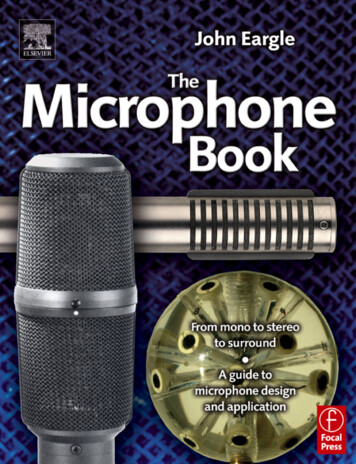
Earg 01.qxd14/9/042:34 PMPage 31: A Short History of the Microphone3FIGURE 1–3Berliner’s variablecontact microphone.from 380 Hz to 2000 Hz, and thus fell far short of the desired response.However, it provided a more efficient method of modulating telephonesignals than earlier designs and became a standard in the Bell system forsome years.Another interim step in the development of loose contact modulation of direct current was developed in 1878 by Hughes and is shown inFigure 1–5. In this embodiment, very slight changes in the curvature ofthe thin wood plate diaphragm, caused by impinging sound waves, gaverise to a fairly large fluctuation in contact resistance between the carbonrod and the two mounting points. This microphone was used by ClementAder (Scientific American, 1881) in his pioneering two-channel transmissions from the stage of the Paris Opera to a neighboring space. It wasHughes, incidentally, who first used the term microphone, as applied toelectroacoustical devices.The ultimate solution to telephone transmitters came with the development of loose carbon granule elements as typified by Blake’s transmitterof 1888, shown in Figure 1–6. Along with the moving armature receiver,the loose carbon granule transmitter, or microphone, has dominatedtelephony up to the present. Quite a testimony to the inventiveness andresourcefulness of engineers working nearly 130 years ago.
Earg 01.qxd14/9/042:34 PMPage 44THE MICROPHONE BOOKTHE RISE OF BROADCASTINGThe carbon granule transmitter and moving armature receiver complemented each other nicely. The limitations in bandwidth and dynamicrange have never been a problem in telephony, and the rather high distortion generated in the combined systems actually improved speechintelligibility by emphasizing higher frequencies. Even after the inventionof electronic amplification (the de Forest audion vacuum tube, 1907),these earlier devices remained in favor.When commercial broadcasting began in the early 1920s, there wasa clear requirement for better microphones as well as loudspeakers.Western Electric, the manufacturing branch of the Bell Telephone system,was quick to respond to these needs, developing both electrostatic(capacitor) microphones as well as electrodynamic (moving conductor)microphones. The capacitor, or condenser, microphone used a fixed electrical charge on the plates of a capacitor, one of which was a movingdiaphragm and the other a fixed back plate. Sound waves caused a slightvariation in capacitance, which in turn was translated into a variation inthe voltage across the plates. An early Western Electric capacitor microphone, developed by Wente in 1917, is shown in Figure 1–7.While first employed as a driving element for loudspeakers andheadphones, the moving coil and its close relative, the ribbon, eventuallyfound their place in microphone design during the mid-twenties. Movingcoil and ribbon microphones operate on the same principle; the electrical conducting element is place in a transverse magnetic field, and itsmotion generated by sound vibrations induces a voltage across the conducting element. Under the direction of Harry Olson, Radio Corporationof America (RCA) was responsible for development and beneficialexploitation of the ribbon microphone during the 1930s and 1940s.FIGURE 1–4Blake’s carbon discmicrophone.FIGURE 1–5Hughes’ carbon rodmicrophone.
Earg 01.qxd14/9/042:34 PMPage 51: A Short History of the Microphone5THE RISE OF MASS COMMUNICATIONSFIGURE 1–6Blake’s variablecontact microphone.Beginning as far back as the 1920s, a number of smaller American companies, such as Shure Brothers and Electro-Voice, began to make significant contributions to microphone engineering and design. Generalapplications, such as paging and sound reinforcement, required ingenious and economical solutions to many problems. Commercial development of capacitor microphones was more or less ruled out, due to therequirements for a cumbersome polarizing supply, so these companiesconcentrated primarily on moving coil designs.The work of Bauer (1941) was significant in producing the ShureUnidyne directional (cardioid pattern) design based on a single movingcoil element. Wiggins (1954) developed the Electro-Voice “Variable-D”single moving coil element, which provided low handling noise withexcellent directional response.Other companies designed crystal microphones for low cost,moderate-quality paging applications. These designs were based on theprinciple of piezoelectricity (from the Greek piezien, meaning pressure),which describes the property of many crystalline structures to develop avoltage across opposite facets when the material is bent or otherwisedeformed. The early advantage of the piezos was a relatively high outputsignal, but eventually the coming of small, high energy magnet materialsruled them out.THE GREAT CAPACITOR BREAKTHROUGH:THE ELECTRETFor many years the penalty carried by the capacitor microphone was itsrequirement for external polarization voltage. In the early sixties, Sesslerand West of Bell Telephone Laboratories described a capacitor microphone which used a permanently polarized dielectric material betweenFIGURE 1–7The Wente capacitormicrophone of 1917.
Earg 01.qxd14/9/042:34 PMPage 66THE MICROPHONE BOOKthe movable diaphragm and the backplate of the microphone. Earlymaterials exhibited significant losses in sensitivity over time, but theseproblems have been overcome. Further improvements have come inminiaturization, enabling electret microphones to be designed for a widevariety of close-in applications, such as tie-tack use, hidden on-stagepickup, and many other uses. Today’s small electret microphone requiresonly a miniature self-contained 5-to-9 volt battery to power its equallyminiature preamplifier. It is a testimony to the electret and its long-termstability and excellent technical performance that the Brüel & Kjaer seriesof studio microphones designed in the 1980s used electret technology.STUDIO MICROPHONE TECHNOLOGYThe microphone is the first stage in the complex and extended technicalchain between live performance and sound reproduction in the homeor motion picture theater. Little wonder then that so much attentionhas been paid to the quality and technical performance of these fineinstruments.Capacitor microphones have dominated studio recording since thelate 1940s when the first German and Austrian capacitor microphonescame on the scene. As with any mature technology, progress comesslowly, and the best models available today have a useful dynamic rangethat exceeds that of a 20-bit digital recorder. With regard to directionalperformance, many newer microphones exhibit off-axis responseintegrity that far exceeds the best of earlier models.At the beginning of the 21st century, it is interesting to observethe great nostalgia that many recording engineers have for the earliervacuum tube capacitor models, especially the Neumann and AKG classicmicrophones of the 1950s. All of this reminds us that technology is sooften tempered with subjective judgment to good effect.THE FUTUREThe microphone per se is so highly developed that it is often difficult tosee where specific improvements in the basic mechanisms are needed.Certainly in the area of increased directionality, via second and higherorder designs, is there additional development engineering to be done.There may never be a direct-converting, high-quality digital microphoneas such, but it is clear that digital signal processing will certainly play animportant part in active microphone array development.New usage concepts include microphones in conferencing systems,with their requirements for combining and gating of elements; andmicrophones in large arrays, where highly directional, steerable pickuppatterns can be realized. These are among the many subjects that will bediscussed in later chapters.
Earg 02.qxd14/9/042:35 PMPage 7CHAPTER2BASIC SOUNDTRANSMISSION ANDOPERATIONAL FORCESON MICROPHONESINTRODUCTIONAll modern microphones benefit from electrical amplification and thusare designed primarily to sample a sound field rather than take powerfrom it. In order to understand how microphones work from the physical and engineering points of view, we must understand the basics ofsound transmission in air. We base our discussion on sinusoidal wavegeneration, since sine waves can be considered the building blocks ofmost audible sound phenomena. Sound transmission in both plane andspherical waves will be discussed, both in free and enclosed spaces.Power relationships and the concept of the decibel are developed. Finally,the effects of microphone dimensions on the behavior of sound pickupare discussed.BASIC WAVE GENERATION ANDTRANSMISSIONFigure 2–1 illustrates the generation of a sine wave. The vertical component of a rotating vector is plotted along the time axis, as shown at A.At each 360 of rotation, the wave structure, or waveform, begins anew.The amplitude of the sine wave reaches a crest, or maximum value,above the zero reference baseline, and the period is the time required forthe execution of one cycle. The term frequency represents the number ofcycles executed in a given period of time. Normally we speak of frequency in hertz (Hz), representing cycles per second.
Earg 02.qxd14/9/042:35 PMPage 88THE MICROPHONE BOOKFIGURE 2–1Generation of a sinewave signal (A); phaserelationships between twosine waves (B).For sine waves radiating outward in a physical medium such as air,the baseline in Figure 2–1 represents the static atmospheric pressure,and the sound waves are represented by the alternating plus and minusvalues of pressure about the static pressure. The period then correspondsto wavelength, the distance between successive iterations of the basicwaveform.The speed of sound transmission in air is approximately equal to344 meters per second (m/s), and the relations among speed (m/s), wavelength (m), and frequency (1/s) are:c (speed) f (frequency) (wavelength)f c/ c/f(2.1)For example, at a frequency of 1000 Hz, the wavelength of sound in airwill be 344/1000 0.344 m (about 13 inches).Another fundamental relationship between two waveforms of thesame frequency is their relative phase ( ), the shift of one period relativeto another along the time axis as shown in Figure 2–1B. Phase is normally measured in degrees of rotation (or in radians in certain mathematical operations). If two sound waves of the same amplitude and
Earg 02.qxd14/9/042:35 PMPage 92: Basic Sound Transmission and Operational Forces on Microphones9FIGURE 2–2Wavelength of sound in airversus frequency; in meters(A); in feet (B).frequency are shifted by 180 they will cancel, since they will be in aninverse (or anti-phase) relationship relative to the zero baseline at alltimes. If they are of different amplitudes, then their combination will notdirectly cancel.The data shown in Figure 2–2 gives the value of wavelength in airwhen frequency is known. (By way of terminology, velocity and speedare often used interchangeably. In this book, speed will refer to the rateof sound propagation over distance, while velocity will refer to thespecifics of localized air particle and air volume movement.)TEMPERATURE DEPENDENCE OF SPEED OFSOUND TRANSMISSIONFor most recording activities indoors, we can assume that normal temperatures prevail and that the effective speed of sound propagation willbe as given above. There is a relatively small dependence of sound propagation on temperature, as given by the following equation:Speed 331.4 0.607 C m/swhere C is the temperature in degrees celsius.(2.2)
Earg 02.qxd14/9/042:35 PMPage 1010THE MICROPHONE BOOKACOUSTICAL POWERIn any kind of physical system in which work is done, there are twoquantities, one intensive, the other extensive, whose product determinesthe power, or rate at which work is done in the system. One may intuitively think of the intensive variable as the driving agent and the extensive variable as the driven agent. Table 2–1 may make this clearer.Power is stated in watts (W), or joules/second. The joule is the unitof work or energy, and joules per second is the rate at which work isdone, or energy expended. This similarity among systems makes it easyto transform power from one physical domain to another, as we will seein later chapters.Intensity (I) is defined as power per unit area (W/m2), or the rate ofenergy flow per unit area. Figure 2–3 shows a sound source at the leftradiating an acoustical signal of intensity I0 uniformly into free space.We will examine only a small solid angle of radiation. At a distance of10 m that small solid angle is radiating through a square with an area of1 m2, and only a small portion of I0 will pass through that area. At a distance of 20 m the area of the square that accommodates the original solidangle is now 4 m2, and it is now clear that the intensity at a distance of20 m will be one-fourth what it was at 10 m. This of course is a necessary consequence of the law of conservation of energy.TABLE 2–1 Intensive and extensive variablesSystemIntensive variableExtensive chanical(rotational)Acousticalvoltage (e)force (f )current (i)velocity (u)watts (e i)watts (f u)torque (T)angular velocity ( )watts (T )pressure (p)volume velocity (U)watts (p U)FIGURE 2–3Sound intensity variationwith distance over a fixedsolid angle.
Earg 02.qxd14/9/042:35 PMPage 112: Basic Sound Transmission and Operational Forces on Microphones11The relationship of intensity and distance in a free sound field isknow as the inverse square law: as intensity is measured between distances of r and 2r, the intensity changes from 1/I0 to 1/4I0.The intensity at any distance r from the source is given by:I W/4 r2(2.3)The effective sound pressure in pascals at that distance will be:p I 0c(2.4)where 0c is the specific acoustical impedance of air (405 SI rayls).For example, consider a point source of sound radiating a power ofone watt uniformly. At a distance of 1 meter the intensity will be:I 1/4 (1)2 1/4 0.08 W/m2The effective sound pressure at that distance will be:p (0.08)405 5.69 PaRELATIONSHIP BETWEEN AIR PARTICLEVELOCITY AND AMPLITUDEThe relation between air particle velocity (u) and particle displacement(x) is given by:u(t) j (t)(2.5)where 2 f and x(t) is the maximum particle displacement value. Thecomplex operator j produces a positive phase shift of 90 .Some microphones, notably those operating on the capacitive orpiezoelectric principle, will produce constant output when placed in aconstant amplitude sound field. In this case u(t) will vary proportional tofrequency.Other microphones, notably those operating on the magnetic induction principle, will produce a constant output when placed in a constantvelocity sound field. In this case, x(t) will vary inversely proportional tofrequency.THE DECIBELWe do not normally measure acoustical intensity; rather, we measuresound pressure level. One cycle of a varying sinusoidal pressure might looklike that shown in Figure 2–4A. The peak value of this signal is shown asunity; the root-mean-square value (rms) is shown as 0.707, and the average value of the waveform is shown as 0.637. A square wave of unityvalue, shown at B, has peak, rms, and average values that all are unity. Therms, or effective, value of a pressure waveform corresponds directly to thepower that is delivered or expended in a given acoustical system.The unit of pressure is the pascal (Pa) and is equal to one newton/m2.(The newton (N) is a unit of force that one very rarely comes across in
Earg 02.qxd14/9/042:35 PMPage 1212THE MICROPHONE BOOKFIGURE 2–4Sine (A) and square (B)waves: definitions of peak,rms and average values.daily life and is equal to about 9.8 pounds of force.) Pressures encountered in acoustics normally vary from a low value of 20 Pa (micropascals) up to normal maximum values in the range of 100 Pa. There is agreat inconvenience in dealing directly with such a large range of numbers, and years ago the decibel (dB) scale was devised to simplify things.The dB was originally intended to provide a convenient scale for lookingat a wide range of power values. As such, it is defined as:Level (dB) 10 log (W/W0)(2.6)where W0 represents a reference power, say, 1 watt, and the logarithm istaken to the base 10. (The term level is universally applied to valuesexpressed in decibels.) With one watt as a reference, we can say that20 watts represents a level of 13 dB:Level (dB) 10 log (20/1) 13 dBLikewise, the level in dB of a 1 milliwatt signal, relative to one watt, is:Level (dB) 10 log (0.001/1) 30 dBFrom basic electrical relationships, we know that power is proportional to the square of voltage. As an analog to this, we can infer thatacoustical power is proportional to the square of acoustical pressure. Wecan therefore rewrite the definition of the decibel in acoustics as:Level (dB) 10 log (p/p0)2 20 log (p/p0)(2.7)In sound pressure level calculations, the reference value, or p0, is established as 0.00002 Pa, or 20 micropascals (20 Pa).Consider a sound pressure of one Pa. Its level in dB is:dB 20 log (1/0.00002) 94 dBThis is an important relationship. Throughout this book, the valu
in engineering and design and young people targeting a career in audio can learn from it. Chapter 1 presents a short history of the microphone. While Chapters 2 through 6 present some mathematically intensive material, their clear graphics will be understandable to those with little