Transcription
The Laser MicrophoneAuthors: Mark Chounlakone, Julian AlverioFiltering Section: Justin TunisAbstractThe human voice can generate sound waves in the range of 300 Hz to 3400 Hz [8].These sound waves vibrate nearby objects, making it possible for an analog electronicdevice to convert these vibrations into an audio signal[1]. One way to accomplish thisconversion from movement to audio is to use a "laser microphone", which reflects alaser off the vibrating object and uses a receiver to capture the laser's reflection. Thereflection of the laser gets deflected as vibrations shift the surface of the vibratingobject. Therefore, if a receiver takes in the oscillating laser signal from a fixed location,the receiver will detect the laser deflections caused by the vibrations that were originallyproduced from an audio signal. The receiver can then filter and amplify this signal, andoutput it as audio. Through this process the laser microphone effectively reproduces theaudio that induced the object's vibrations.The laser microphone is able to reproduce audio detected from a vibrating surface withrelatively high accuracy: less than 8% distortion. As an additional feature, the lasermicrophone is also able to transmit audio via amplitude-modulated laser signal, capturethe laser signal, and output the audio. Thus by using a laser based system that capturesoscillations in the position of the laser, the laser microphone is able to accuratelyreproduce both the audio that induced an object's vibrations and audio transmitted vialaser communication.IntroductionHuman speech is composed of sound waves that vibrate the objects nearby. The goalof this project is to create an analog electronic device that can read in a signal from avibrating object and reproduce the audio that originally caused it to vibrate.This projectachieved this goal with the laser microphone, which is a device that shoots a laser atthe vibrating surface and captures the reflection with a receiver. The vibrating surfacetranslates the position of the laser's reflection, thus allowing the receiver to output thelaser input signal through speakers as audio. Thus the laser microphone can reproducethe original audio signal that induced the object's vibrations through a speaker.To function as desired, the device needed to be able to filter out all frequencies in theinput laser signal outside of the human speech frequency range. Secondly, the device
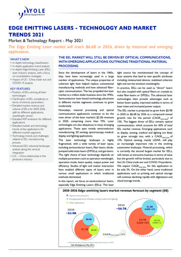
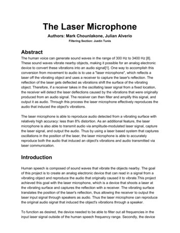
needed to be able to output audio through a class D amplifier using a switchingfrequency of at least 400 KHz. Additionally, the device needed to be able to supportdirect laser-to-receiver audio communication. In order to meet these functionalrequirements, the electronic part of the system is composed of four stages. The firststage is laser transmission, where the laser will be amplitude-modulated if the device istransmitting directly from laser to receiver. The second stage is a laser reception stage,with a reverse-biased photodiode in a transimpedance amplifier. This transimpedanceamplifier offers high common mode gain rejection and high gain. The third stage is ahigh order signal filter. The last stage is a class D audio amplifier, which switches at afrequency of at least 400 KHz and outputs audio at a maximum voltage swing of at least8 Vpp.While the main focus of the project is exploring the design of circuitry used to reproducespeech from a captured signal, some mechanical characteristics of the system are alsokey to the system's success. There are two key mechanical properties that the lasermicrophone depends on. The first is the acoustic properties of objects which generatevibrations from sound waves. The second is the reflectivity of the object’s surface.Figure 1Depiction of how a laser can be used to detect mechanical deflections.Figure 1 shows both of these mechanical properties at work. As the surface shown onthe left shifts, the reflected beam of the laser changes position. Since this project wasfocused around the electronics, we chose to simplify the mechanical challenges bybuilding a few setups with ideal mechanical properties. These setups are described inthe system design.System Design
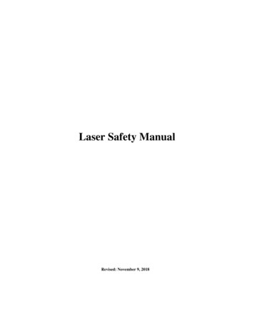
Figure 2A flow diagram of audio reconstructed from the laser microphoneThe laser microphone is a very sensitive device which must detect minute surfacedeflections caused by audio. The detection is done using a photodiode and atransimpedance amplifier. The signal observed by the photodiode is a noise injectedversion of the audio signal of interest. Noise is injected through mechanical vibrations,ambient light, and the photodiode itself. To produce a coherent reconstruction ofspeech, the l laser microphone filters out the noise in the transimpedance amplifier andthe preamplifier. Once the audio signal has been cleaned, it is sent through the class Damplifier which then plays back the signal on a speaker.
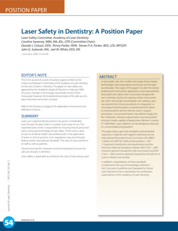
Laser TransmitterThe first stage of the laser microphone is the transmitter. For this project, there weretwo modes of transmission, each built separately. The first mode was reflectedtransmission. This is the mode that has been discussed the most so far. The laser isshot at a vibrating surface and the receiver captures the reflection. The circuit wassimply a 5mW red laser pointer connected directly to a 5v supply which is not shown.Figure 3A depiction of the circuit used to directly communicate to the receiver with the transmitterThe second mode of laser transmission was a direct communication mode. In thisregime, the laser is modulated with an audio signal and the receiver captures the beamdirectly. The circuit used for direct communication is shown in Figure 3. The laser diodeis depicted as an LED, D1. The power output of the laser had to be modulated with thesignal being sent so that the circuitry on the receiving end could reconstruct the signal.To do this an audio signal centered around 5V was sent through a simply op amp bufferwhich drove the laser diode. By driving the laser diode with a modulated voltage aroundit’s operating voltage, the power is modulated. While this circuit works, it is not the mostelegant way to modulate the laser. Laser diodes are fairly sensitive devices and will diewithout a proper current regulating circuit. This laser diode was not a laser pointer so itused a as resistor a current regulator rather than a proper laser driver. A smarter designwould use a voltage controlled current regulator to modulate the current at a fixedvoltage.Laser Receiver
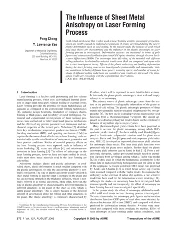
Figure 4A depiction of the photodiode and transimpedance amplifier used to receive the signal.The second stage of the device was the laser receiver. This stage was designed tocapture the reflected laser signal and turn it into a voltage. The receiver was composedof a photodiode and a transimpedance amplifier (TIA). In Figure 4, the photodiode isdepicted as a normal diode between the inverting inputs of two op amps. Thephotodiode is the sensor that captures the laser signal. In reverse biased mode, thephotodiode has a reverse current which is linearly related to the light irradiance. Once areverse current is generated, the TIA the current into a voltage. The TIA topology shownin Figure 4 incorporates a differential amplifier. The differential amplifier gets rid ofinterference caused by ambient light using common mode rejection.The reason the isnecessary is explain later in this section.This TIA topology can be described in two parts. The first part is composed of two opamps to create two inverted signals. The non-inverting inputs of the op amps are set to5v and 0v such that the photodiode is reverse biased. When light generates a reversecurrent in the photodiode, the current must pass through both resistors. Ohm’s lawstates that V IR, so the current passing through the resistors generates proportionalvoltage signals. The photodiode’s datasheet states that the reverse current is on theorder of tens of microamps, so 920K resistors were selected to gain the current. Theoutput of the bottom op amp is the inverse of the top op amp’s output with some dcoffset. These two signals are then ac coupled by the 1mF/2.2M capacitor resistor pair,which gets rid of the offset. The capacitor and resistor pairs are ac couplers which also
act as high pass filters. I just choose a frequency, .07 Hz, below the vocal range as acorner frequency. The second stage of the transimpedance amplifier is a differentialamplifier which was previously described.Figure 5A depiction of the photodiode and the original transimpedance amplifier design.So why was the differential topology chosen? Originally we had a different design. Thisone was more simple but without the second stage of the amplifier, ambient light wasinterfering with the signal. The difficulty with the ambient light did not come from thesteady state offset, but from changing ambient light. Just moving around the photodiodewould change the amount of ambient light detected, causing the entire signal to shift.Originally we built a box to isolate the photodiode from ambient light, but alignmentbecame much more difficult. Professor Jacob White proposed this new topology as anelegant solution to the ambient light issue. So to reduce the amount of time spent fixinga mechanical issue, the design was expanded to compensate for the interference andthe box was no longer necessary. Another nice attribute of the circuit above was that itdoubled the signal we received since the current flowed through two resistors. Thistopology is also able to add more gain in the differential amplifying stage.Signal FilteringThe signal from the transimpedance amplifier contains noise from sources like AChum from equipment, low frequency rumbles, and mechanical vibrations. Amplifying thesignal at this point would produce a distorted output and snooping would be infeasible.In order to cope with this we have included a voice frequency band-pass filter toattenuate noise outside of the frequency range of human speech, which is from 300 Hzto 3 kHz.The circuit consists of a 3rd order high-pass filter cascaded with a 3rd order low-passfilter. Each of those components consisted of a first-order RC filter cascaded with a
Sallen-Key topology second-order filter. The actual circuit had measured cutofffrequencies of 315 Hz on the high-pass filter and 3050 Hz on the low-pass filter, whichis right around the vocal-range we were aiming to isolate. Additionally, the circuitprovided a measured -60 db/decade attenuation outside of the passband whichtranslates to a -1000x gain, meaning noise significantly outside of the 300 Hz to 3 kHzrange was attenuated to a negligible level.We also experimented with higher-order filters as well as adding gain with the filters.A fifth-order bandpass filter that had been constructed was difficult to tune to the propercutoff frequencies because a large number of components were involved. Most of theresistors and capacitors in lab have a 5% margin of error, which adds up quickly whenbuilding a module with many of these components. While it would certainly be possibleto have the circuit operational, the time-to-benefit ratio we would have received from theextra work would not have paid off. Adding gain to the system was also a little tricky asit ended up injecting noise back into the system and created a distorted output. Onework-around would have been to include a simple, non-inverting op-amp configurationwith gain after the output of the filter; however, this became unnecessary as the signalfrom the transimpedance amplifier was large enough that no extra gain was neededfrom this part of the system.Fig 6. Vocal Band-Pass FilterAudio AmplifierIn order to output the audio signal from the filter stage, the laser microphone uses a fullbridge class D amplifier. Below is a diagram of the amplifier:
Figure 7: Full-Bridge Class-D AmplifierThe implementation operates in four stages: the pulse-width modulation stage, the gatedriving stage, the power stage, and the output stage. Each stage presented a uniqueset of design challenges.Pulse-Width Modulation StageFigure 8: Pulse-Width Modulation StageThe amplifier converts from a sinusoidal audio input signal to a pulse-width modulatedsignal by comparing the audio input with a sawtooth wave. The frequency of thesawtooth wave determines the "switching frequency", or the frequency with which theMOSFET's turn on and off to produce audio output. In order to meet the specifications,
the sawtooth had to have a frequency of at least 400 KHz. In the next section isdiscussion of the sawtooth generation design using a comparator.In order for the pulse-width modulated signal to be able to activate the gate drivingstage, the pulse-width modulation stage had to produce a modulated output, as well asits complement, and both of these signals had to be very clean.By providing an LM311 comparator with a sawtooth and audio input, the output of theLM311 was the pulse-width modulated signal. To ensure the signal output signal wasquite clean, laser microphone passes the comparator output through an inverter, thenthrough a low pass filter, and then through another inverter. The low pass filter acts as a"glitch filter", to eliminate any high frequency noise present in the signal. This highfrequency noise may come from unwanted noise in the comparator inputs causingunwanted, high-frequency switching. The inverter steps force the signal to be at a clean5V or 0V at all times, as opposed to something in between. This, in addition todecoupling capacitors, allows the microphone to attain a very clean signal, as shownbelow in figures 9 and 10. The PWM stage used an additional inverter to produce thecomplement of the original PWM signal.Figure 9: Oscilloscope trace showing the PWM output and its complement. The bluecursor shows the gate driver's "logic low" cutoff
Figure 10: Oscilloscope trace showing the PWM output and its complement. The bluecursor shows the gate driver's "logic high" cutoffFigures 9 and 10 demonstrate a very clean output of the pulse-width modulation stage,where the logic high is well above the logic high cutoff and the logic low is well belowthe logic low cutoff. This output then fed into the next stage: the gate driving stage.This stage in particular presented a number of design challenges. One key objectivewas produce two clean, complementary PWM outputs without causing so much of adelay between the two signals that it causes shoot-through with the MOSFET's in thepower stage. The original solution to this was to use a complementary comparator. TheLT1016 produced a complementary output with minimal delay, and seemed like theideal solution. However, the chip proved to be simply too sensitive to provide a cleanoutput and the implementation was unable to use the chip altogether. It turned out that,even a small stray capacitance could cause the output to be very noisy. After theimplementation no longer used the LT1016, the new designs were able to produce avery clean signal.Gate Driver Stage
Figure 11: Gate Driver StageThe gate driver stage takes inputs from the PWM stage and turns the MOSFET's onand off very rapidly. The gate driver is able to switch the MOSFET's quickly by pumpinga large amount of current into the gate, in order to overcome the gate capacitance.One key design consideration is the generation of dead time. If the high and low sideMOSFET's turn on and off without any delay in between, shoot-through can occur.Shoot-through is when both MOSFET's are on at the same time. This can damage theMOSFET's and will cause distortion in the signal output to the final stage. In order toavoid shoot-through, there must exists a dead time in between the two MOSFET'sturning on; a time in which neither MOSFET is on. Though the gate driver does havesome dead time generation, the MOSFET's will still experience shoot through withoutadditional dead time generation. In order to generate additional dead time, the lasermicrophone utilizes a schottky diode in parallel with a small resistor. This pair causesthe turn-on time to be slightly delayed due to the RC time constant the resistor creates,while the turn off time is not delayed. The resistors required particular attention -- toosmall of a resistor does not generate sufficient dead time and allows for shoot-through,while too large of a resistor generates too much dead time.
Since the gate driver switches very rapidly and draws a relatively large amount ofcurrent, the laser microphone utilizes a passive second order low pass filter in orderavoid injecting high frequency noise into the power supply. The filter is the same usedfor the high side MOSFET and will be discussed in the next section.The gate driver stage produces a very clean output to the MOSFET's. In figure 12 belowyou will see the gate driver input compared to the MOSFET gate voltage on the output.Figure 12: Oscilloscope Trace Showing the Low Side Gate Driver Input in Blue and theLow Side MOSFET Gate Voltage in Purple (Purple Trace Shifted Up for Visibility)Power Stage
Figure 13: Half of the Power StageThe power stage is composed to two symmetrical halves, like the one shown in figure13. The power stage works by rapidly switching high side and low side MOSFET's(shown above) very rapidly to amplify the PWM signal. However, since this stage isdrawing substantial amount of current and switching very rapidly, the laser microphoneimplements a passive second order low pass filter in order to keep the power supplynoise-free.
Figure 14: Simulation of Current Demand on Power Supply, using a Passive SecondOrder Filter Without DampingDesigning this filter presented some interesting design challenges. A regular secondorder filter would have a very high resonant peak, as shown in figure 14. A filter with thelaser snooper parameters but no damping would have a resonant peak of almost 4 dB.After adding damping, the resonant peak almost completely disappeared, as shown infigure 15.Choosing values for the circuit was difficult. Choosing values was a matter ofmaximizing the size of the resistor so it was at least a 1 ohm resistor, minimizing thesize of the inductor such to minimize its parasitic resistance, maximizing the size of thelarge capacitor such to minimize DC power dissipation through the resistor, andoptimizing the size of the small capacitor to set the frequency cutoff at an appropriatevalue. The laser microphone's functional frequency cutoff is approximately 13 KHz, aftertaking into account parasitics. This is a near ideal frequency cutoff for the lasermicrophone.Since 1.2 ohm resistors were not available, the laser microphone implements a 1 ohmresistor and utilizes the 0.2 ohm parasitic resistance from the large damping capacitor.
,Figure 15: Simulation of Current Demand on Power Supply, using a Passive SecondOrder Filter Without DampingFigure 16: The Simulation Run to Produce Figure 15Output Stage
Figure 17: Half the Output StageThe PWM from the output from the power stage then passes through a second order,low pass filter to the speaker. The filter is the same as the one used with the powersupply filtering, only with the inductor in the first part of the filter to avoid rapidlycharging and discharging the capacitors. This then produces an output to the speaker.The output was actually relatively clean at times, allow the class D amplifier to playmusic and test tones. Below is a scope trace of the outputs across load resistors.Figure 18: Output From the Full Bridge Class D with a Sine Wave InputThe Ramp Generator
Figure 19A depiction of the ramp generating circuit.One of the requirements we had was to have the class D amplifier operate at 400kHz.This frequency is set by the ramp generator. Figure 19 shows an implementation of theramp generator. This design uses a current source and an LM311 comparator chargeand discharge a capacitor. The ramp can be observed by probing the capacitor. Thepnp to cap setup on the right is a current source to linearize the rise of the ramp (I Δ V/ Δ t*C). Since the fall time is relatively small compared to the rise time of the ramp,1/ Δt is approximately 400kHz. The current source is calibrated to about 23.11microamps and the desired voltage swing is 5Vpp. So C I*Δt/ΔV which is about 10 nF.The non-inverting side of the LM311 was connected to the threshold voltage and theinverting side was connected to the capacitor. The LM311 has an npn type transistorinternally connected to the output. Another npn was connected to the internal npn as aninverter and its collector was tied to the base of a pnp with a 1K pullup resistor. Theallowed the pnp to act as a proper discharge path. So in operation if the capacitorcharged up to the threshold voltage, the LM311’s internal npn would turn off, allowingthe external npn to turn on. This would then trigger the pnp to turn on, which dischargedthe capacitor.
Test SetupThere was a total of three test configurations. The first level was testing the laser’sability to pick up vibrations. This was done by attaching a mirror to a speaker andcontrolling the speaker with a signal generator. The laser was reflected off the mirroronto the receiver, the speaker was then driven at some known frequency, and thereceived signal was compared to the known frequency. The results confirmed that thereceived signal matched the known frequency. The process was iterated to tune gainsin the TIA to obtain a voltage range large enough for audio. Then the receiver wasconnected to a class AB amplifier to test the audio quality. Once the filter was complete,it was connected between the receiver and the audio amplifier. The addition of the filtersignificantly reduced noise. Finally, we moved onto testing the system on a window. Thewindow turned out to be too dirty, and our tools for alignment were mediocre. If we hadbeen able to shoot the laser at the center of a clean window we believe the systemwould have performed well. So to emulate an ideal window we taped a mirror to acardboard box and reflected the laser off of that. When comparing the output of thesystem to a pure sine wave input from the function generator, the mean percentageerror was less than 3%. Qualitatively, this means that the output was clear and crispaudio.Risk Assessment ChartFunctionalRequirementRiskCountermeasureAdding modulation toThe sound outputour laser at theAudio output must be might be too noisy fortransmitted andhuman interpretablehumans to easilydemodulating theunderstandsignal at the receiver.High order filtering
and amplifying audiosignal beforeoutputting.The receiver mustreceive the laser'sreflection directlyAt first we will have toset up our testingaparatus very carefullto optmize theThe receiver may not location and angle ofbe in a good positionthe receiver.to receive the laser. Eventually we hope toadd a controls systemto manipulate a baseand optimize thelocation and angle.We have the speakertest rig which shouldallow us to observeMedium - It's beenour systemsdocumented andbehaviour in adone. This will come controlled setting. WeLaser capturing audiodown to calibratingalso will be touring asignaland limitations of the laser lab and checkingcomponents weour data sheets tochoose.better ourunderstanding andintuition of oursystem's behaviour.Again we have thespeaker and we havethe ability to trybouncing the laser offother objects. WeHigh - This is verycould also purchase adependent on theWindow bouncing thesmall sheet of glass orproperties of the glasslaseracrylic (whichever iswe bounce on and wemore ideal) and makecannot control this.a demoing mirror withideal physicalproperties (should geta better idea duringlab tour).Audio waves strongenough to shake thewindow.Low - This isdependent on theproperties of the glassas well, but we caneasily increase thevolume to get a largerwave.As mentioned, we cangenerate a loudersound against theglass to get it tovibrate.
Optics to AudioThe system has beenbuilt before so theremust be either a workaround tononlinearity. We justneed to familiarizeMedium - This isourselves with thesomething that noneproperties of theof us have experiencephototransistor wewith and it is possibleselect.that the conversion isThere also is filteringnonlinearand amplificationinvolved, but we havehad lab experiencewith this and so therisk there is relativelysmall in comparisonResults and ConclusionAfter testing and modifying the design of the laser microphone, it was calculated that thetotal harmonic distortion was less than 8%. This was calculated using a mean squarepercent error. Two signals were measured one from an input speaker and one from theoutput of the laser microphone. The two signals were captured on an oscilloscope, andexported as csv files. The percent error of each data point was calculated (percent error (actual-expected)/actual), squared and averaged. The laser microphone was moresensitive when the sun was down. This could have been due to saturation of current inthe photodiode during daylight. Overall at peak performance, the laser microphone wasable to pick up music, and even people talking on the other side of the lab. There didseem to be some form of feedback which plagued the system. It was unclear whether itwas audio feedback or electrical feedback. Jason suggested that isolating power acrossthe system could reduce the feedback if it was electrical. Given the nature of the systemit is plausible that the speaker was vibrating both the table that the receiver was on andthe cardboard box. This would cause large “feedback” spikes as the speaker got louder.The project overall was a great exercising in analog circuit design.References1. https://www.academia.edu/13549827/Sound Waves Transmission via IR LaserThe Laser Microphone Device?auto download
2. ce-1.aspx3. dowell-2008-pink-noise-fundamental-limit.pdf (pink noise in photodiodes)4. https://en.wikipedia.org/wiki/Amplitude modulation5. https://en.wikipedia.org/wiki/Optical communication6. tion.html7. http://www.vishay.com/docs/81521/bpw34.pdf8. https://en.wikipedia.org/wiki/Voice frequency9. er-design-for-optical-vibrometry/
audio that induced the object's vibrations. The laser microphone is able to reproduce audio detected from a vibrating surface with relatively high accuracy: less than 8% distortion. As an additional feature, the laser microphone is also able to transmit audio via amplitude-modulated laser signal, capture