Transcription
Raspberry PI with Standard CODESYS V3First StepsVersion: 3.0Template: templ tecdoc en V1.0.docxFile name: RaspberryPI CodesysV3 FirstSteps EN.doc 3S-Smart Software Solutions GmbH
CONTENTPageProduct description32Installation, configuration and icensing via the CODESYS Development SystemLicense backupLicense Reactivation455663Example ectMCP3008 SoftMotion Servo 11213134Connecting additional devices via I²C and SPI145Screenshots16Template: templ tecdoc en V1.0.docx1 3S-Smart Software Solutions GmbH
CODESYS Inspiring Automation Solutions13/16Raspberry PI with Standard CODESYS V3Product descriptionProduct descriptionThis product contains a CODESYS Control application for Raspberry Pi (see http://www.raspberrypi.org/) aswell as driver support for the extension modules Raspberry PiFace Digital, Raspberry Pi Camera and severaldevices/breakouts with I²C communication interface.The recommended operating system ‘Raspian’ can be downloaded here:Common download page: https://www.raspberrypi.org/downloads/Latest version: https://downloads.raspberrypi.org/raspbian latestThis product can be installed via CODESYS Update Manager (CODESYS PlugIn RPIUpdate) on a Linuxdistribution (Raspbian). After starting Raspberry Pi without a valid license, CODESYS Control runs for two hourswithout functional limitations and shuts down automatically.The runtime system does not have real-time behavior. Its Jitter depends on many factors, especially on parallelexecuted Linux applications, and is ideally about 50µs with maximum values of 400µs.Note: The CODESYS Control runtime system for the Raspberry Pi CODESYS supports CODEYS BACnet. ABACnet stack demo version is provided with the runtime system. A full verson is available in the CODESYSStore.This product supports the following functionalities:- CODESYS EtherCAT Master- CODESYS Profinet Master- CODESYS Modbus TCP Master / Slave- CODESYS Modbus RTU Master / Slave (serial interface must be supported by and installed in the OS)- CODESYS WebVisu- CODESYS SoftMotion CNC- CODESYS OPC/UA Server- CANopen via EL6751 Gateway- CODESYS EtherNet/IP Scanner- CODESYS EtherNet/IP AdapterThis product consists of:- Debian package with CODESYS Control for Raspberry Pi- CODESYS Plugin to install and update the package on a Raspberry Pi- CODESYS device description files for Raspberry Pi, Raspberry PiFace Digital, Raspberry PiFaceControl&Display, Raspberry Pi Camera, several devices/breakouts with I²C (SRF02, Adafruit PWM,MPU6050, MPU9150, AK8975), SPI (MCP3008, MCP23S17) or 1-wire (DS18B20) communicationinterfaceThis product offers amongst other things the possibility to plug and control additional devices via SPI, I²C or 1wire.This product is provided for testing and training purposes. Usage for industrial purposes is not recommended. 3S-Smart Software Solutions GmbH
CODESYS Inspiring Automation Solutions24/16Raspberry PI with Standard CODESYS V3Installation, configuration and licensingInstallation, configuration and licensingStart CODESYS and the PackageManager, which you can find in the menu “Tools”. Install the package file thatyou have downloaded from CODESYS Store.For the installation of CODESYS Control onto your Raspberry Pi you will need an operative Raspbian OS. If thisis not yet installed on your device, please execute the steps described in the section Preparations. Elsecontinue with Installation.2.1 PreparationsFollow the steps described on https://www.raspberrypi.org/downloads/ in order to install an OS onto the SD cardof your device. We recommend the use of Raspbian.Reboot Raspberry Pi with this SD card afterwards. In order to obtain a valid IP address, the device should beconnected to a network with a DHCP server.To find out the network address, you may either plug a keyboard, mouse and a monitor to your device, log in(user: pi, password: raspberry), open a console and issue the command ifconfig. Or you can ping thedevice from the windows console with its network name (default: RaspberryPi) and obtain the IP address.Alternatively, you can start CODESYS and execute the command “Update Raspberry Pi” in the menu Tools,where you execute “Scan” and find the list of IP addresses of Raspberry devices in your network.With the IP address you can also log in via SSH using tools like Putty (user: pi, password: raspberry).1. Basic configurationa. From a console run sudo raspi-config and execute the following actionNote: As from Debian version “Jessie” there is also a graphic configuration user interface,providing exactly the same settings.b. Optional: Rename the device (8 Advanced Options).c. Optional: Activate the camera (5 Enable Camera).d. Exit and restart the device.2. Activate the interfaces i²c, spi, 1-wirea. Connect via SSH (e.g. using Putty) with your deviceb. Edit the file /boot/config.txt e.g. usingsudo nano /boot/config.txtc. Make sure that the following lines are in this file (and not deactivated with #):d. Optional: i²cdtparam i2c arm on 3S-Smart Software Solutions GmbH
CODESYS Inspiring Automation Solutions5/16Raspberry PI with Standard CODESYS V3Installation, configuration and licensinge. Optional: SPIdtparam spi onf. Optional: 1-wiredtoverlay w1-gpio-pullup,pullup 13. Optional: Prepare cameraa. un raspi-config (see 1) and execute “Enable Camera“.b. Connect via SSH (e.g. with Putty) to your device (standard user “pi”, password “raspberry”) andexecute the following commands in your shell in order to install the c:sudo apt-get updatesudo apt-get dist-upgradesudo rpi-updategit clone https://github.com/silvanmelchior/RPi Cam Web Interface.gitcd RPi Cam Web Interfacechmod u x RPi Cam Web Interface Installer.sh./RPi Cam Web Interface Installer.sh installc. Start a web browser and connect to your device at http:// network address In case the installation was successful, the UI of RPi Cam Control should open and you canconfigure your camera.2.2 Installation1. In CODESYS execute the command „Update RaspberryPi (menu Tools).a. Select the desired versionb. nter the correct login data (default: pi/raspberry)c. Select the IP address of your deviced. Click OK and check if the message window prompts that the update/installation has beensuccessfully executed2. After a restart the device will be ready to be used with CODESYS.2.3 Licensing via the CODESYS Development SystemRequirements: PC with CODESYS Development System, internet access and connected Raspberry Pi.Licensing is done via PC / notebook with the CODESYS Development System and the connected Raspberry Pi.The license entries are edited via double-click on the device under “PLC settings” / “Edit licenses ”. 3S-Smart Software Solutions GmbH
CODESYS Inspiring Automation Solutions6/16Raspberry PI with Standard CODESYS V3Installation, configuration and licensingThe license activation is done under “Install licenses” / “Activate license” by entering the ticket number andtransfer of the license to the CODESYS Software Key (Softcontainer).Note: On activation the license is bound to a single Raspberry Pi and can only be reactivated on the samedevice!2.4 License backupDifferent processes (e.g. loss of power) can lead to a corruption of the file system of the Raspberry Pi. To backup the license the following proceeding is recommended:1. Activation of the license (as described above)2. Reboot of the Raspberry Pi3. Backup of the license file on an external storage deviceTo safe the license file move to the folder “backup” on the Raspberry Pi (accessible in CODESYS via doubleclick on the device under the tab “Files”).Store the content of the folder („3SLicenseInfo.tar“) to an external storage device.2.5 License ReactivationTo reactivate the license file has to be copied to the folder “restore”. Subsequently the system has to berebooted. 3S-Smart Software Solutions GmbH
CODESYS Inspiring Automation Solutions37/16Raspberry PI with Standard CODESYS V3Example applicationsExample applicationsIn the installation path (that you have noted down during installation of the package) you will find the followingexample projects:3.1 Webvisu.projectThis example shows how CODESYS web visualization can be used. Open the project and download it onto yourRaspberry Pi by doubleclicking on the node “Device” in the device tree (left hand side). Then press “Scannetwork” in the communication dialog tab and select your device that should now appear under the name“RaspberryPi”, if the device is in the same network with your programming PC. Select it and run “log in” from themenu “Online”. Then start the application with F5.Start an internet browser (possibly also on your smartphone) and connect to NetworkAddress :8080/webvisu.htm.In your browser you will see the visualization that has been designed in the project:3.2 Camera.project(Precondition: Raspberry Pi Camera is connected and installed, see 2.1.)This project shows how you can use Raspberry Pi Camera (extension hardware) to take a picture and save it asfile. Please note that on some hardware models the “RPi Cam Control application” must be deactivated. Useyour browser to connect to the configuration page Netzwerk-Adresse :8080\webvisu.htm and execute“stop camera”.Download the application to your controller, start the program and set the variable xTakePicture to TRUE. Thecamera will take a picture and store it in the local file system with the name „Picture.jpg“.You can copy this file onto your programming PC with the help of the file dialog (doubleclick “Device”, tab“Files”, Button “Update” on the right side etc.).3.3 CameraStream.project(Precondition: Raspberry Pi Camera ist angeschlossen und installiert, see 2.1.)This project shows how a camera stream or single camera picture can be included in your web visualization. 3S-Smart Software Solutions GmbH
CODESYS Inspiring Automation Solutions8/16Raspberry PI with Standard CODESYS V3Example applicationsDownload the application to your controller and start the program. Start an internet browser and connect to Network Address :8080\webvisu.htm. There you see the live stream of your cam in the upper window part andthe last taken single picture in the lower part; you can update the latter by pressing the button next to it.Please note that, depending on the version of the „RPi Cam Web Interface“ and the contained Apacheinstallation, the default path changes from „/var/www/“ zu „/var/www/html/“. If applicable, this path must beadapted in PLC PRG in line 3.3.4 GPIO.projectThis project shows you can use free GPIOs. In the configuration of the GPIO device in the device tree thefunction of each GPIO can be defined: 3S-Smart Software Solutions GmbH
CODESYS Inspiring Automation Solutions9/16Raspberry PI with Standard CODESYS V3Example applicationsThe inputs and outputs are available as DWORD in the tab „GPIOs I/O Mapping“. Bit X of the DWORDcorrelates with GPIO X .In this example GPIO18 is used as output and blinks, controlled by a timer FB in PLC PRG. A visualizationscreen displays the input values of the GPIOs and allows setting outputs.For using the additional GPIOs of the hardware variant Raspberry Pi B we provide you with a separate GPIOdevice, that can be plugged into the slot “GPIOs” in the device tree.Please note that depending on other drivers that might be loaded, some GPIOs can be blocked and be notavailable for general purpose.3.5 PiFace.project(Precondition: Raspberry PiFace Digital is connected)This example shows the usage of Raspberry PiFace Digital (8 digital inputs and outputs).Open the project, download it to the controller and start it. The simple application in PLC PRG controls the relayoutput K0 depending on the key button S1 (on-switching of K0 is delayed for 1s) and the relay output K1depending on button S2 (off-switching is delayed for 500ms).Please note that this driver allows connecting more than one PiFace devices (hardware address is set with thejumpers JP1, JP2) by setting the corresponding parameter in the PiFace device in the device tree.The library SPI PiFace that operates as driver is provided as source code and can be seen as example how tocommunicate to other devices via SPI. The communication bases are on the library RaspberryPiPeripherals, forwhich reference documentation is provided (see online help (F1) - Libraries).3.6 PiFaceIoDrv.project(Precondition: Raspberry PiFace Digital is connected)This example is similar to the one before. Instead of providing the I/O data as inputs of an automaticallyinstanced function block, the example implements the data exchange as standard PLC IO driver via a processimage, how it is typically done on PLCs.The driver library IoDrvPiFace.library is provided as source code.3.7 PiFaceDisplayAndControl.project(Precondition: Raspberry PiFace Control&Display is connected)This example shows how the two-lined textual display and the input buttons of this device can be used toprogram a parameter editor.Note that PiFace Control&Display communicates via SPI port 1 ('/dev/spidev0.1') that needs to be set in the SPImaster instance in the device tree. By adding a PiFace Control&Display device, a FB instance is automatically 3S-Smart Software Solutions GmbH
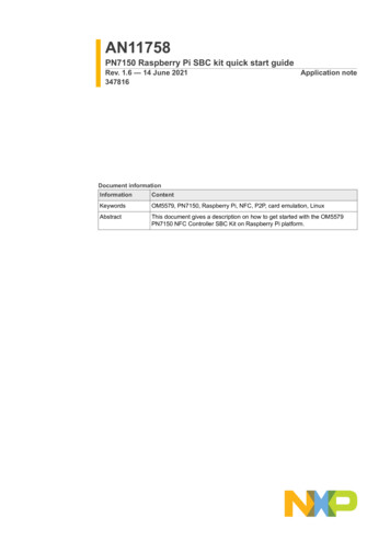
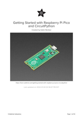
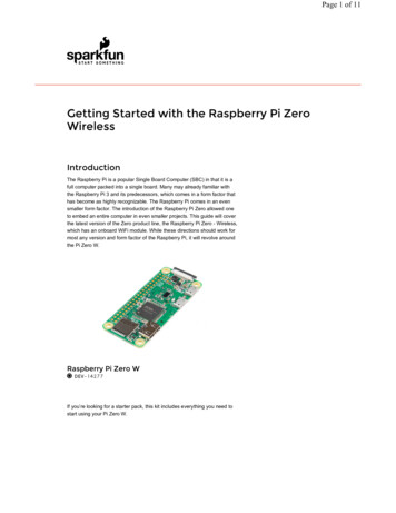
CODESYS Inspiring Automation Solutions10/16Raspberry PI with Standard CODESYS V3Example applicationsgenerated, which offers several methods and properties and lets the application control the device and returnsthe actual values of the switches, where the single bits (0.7) of the output variablke bySwitches represent thefollowing switches:56012374In the example application the FB instance is passed over to an instance of the FB ParamListPiFace, thatimplements the logic of a parameter editor. In the view mode you can step through the parameter list using thenavigator switch (6/7). Pressing it (5) shows details of the parameter of the first line. This detailed view can beexited with 4. By pressing 5 once again you enter the editing mode. Now you can modify the value of theparameter with the switches 0 and 1. Button 2 stores the parameter, button 4 exits the editing mode and goesback to the detailed view.3.8 I2CExample.project(Precondition: special hardware is connected via I²C)This example communicates with the following breakouts via I²C: Adafruit 16-channel/12-Bit PWM SRF02 (supersonic distance sensor) Drotek IMU 9DOF - MPU9150 (gyroskope, accelerometer, compass)The libraries I2C * that implement the data exchange are provided in source code and can be used as examplefor additional interface connections. The communication bases on the library RaspberryPiPeripherals, for whichreference documentation is provided (see online help (F1) - Libraries).3.9 MCP3008 Temperature.project(Precondition: special hardware is connected via SPI)This example shows how the value of an analog temperature sensor (LM35), that is connected to an A/Dconverter chip (MCP3008), can be read in CODESYS via SPI. MCP3008 can process 8 analogue channels. Inthis example we use only one of these. The following test installation is used:Die für die Anbindung verantwortlichen Bibliotheken SPI MCP3008.library werden als Sourcecode zurVerfügung gestellt und können als Beispiel für andere Anschaltungen dienen. Basis für die Kommunikation überSPI ist die Bibliothek RaspberryPiPeripherals, deren Schnittstellen dokumentiert sind. 3S-Smart Software Solutions GmbH
CODESYS Inspiring Automation Solutions11/16Raspberry PI with Standard CODESYS V3Example applications3.10 MCP23S17.project(Precondition: special hardware is connected via SPI)This example shows how a port expander chip (MCP23S17) can be used. The hardware should be connectedto the Pi in the following way:In the device settings you can specify, the direction (input/output) of the GPIOs and for inputs you can activate apull-up resistor. Depending on the wiring of the hardware address pins, the address must be set in theconfiguration screen.3.11 OneWire.project(Precondition: 1-wire temperature sensor is connected)This example shows Raspberry Pi scanning the devices that are connected via 1-wire and reading data from atemperature sensor DS18B20. The 1-wire data line is connected to GPIO4.Each 1-wire device has its unique ID that is used to address it. Hence one needs to set the ID in theconfiguration screen of every device before using it.This example helps to find out the ID of the connected devices. It shows two functions:1. Display the result of the scan in a visualization screen. This helps to find out the IDs of the connecteddevices.2. Show the temperature of a DS18B20 temperature sensor, if it is configured correctly. 3S-Smart Software Solutions GmbH
CODESYS Inspiring Automation Solutions12/16Raspberry PI with Standard CODESYS V3Example applicationsNote that the data exchange via 1-wire takes quite a lot of calculation time in this implementation, during whichthe task is blocked. Therefore it is recommended for time critical applications to assign the 1-wire devices to atask of low priority (see device configuration, tab I/O exchange, buscycle options).3.12 SoftMotion Servo Example(Precondition: an Adafruit 16-channel/12Bit PWM circuit board is connected via I²C. On its first PWM channel aservo motor is connected)This example shows, how CODESYS SoftMotion can be used with modelbuilding servo motors. An additionalcircuit board, Adafruit ID 815, acts as communication interface.Open the project and download it to your Raspberry Pi. The motor starts continuously to turn. This has beenprogrammed in SFC in PLC PRG, which first enables the axis and then moves it between the positions -60 and 60, which had been configured as limit positions.The set position command is transmitted to the servo via a PWM interface. In a fixed cyclic period (default:50Hz, parameter of device Adafruit PWM Softmotion) a HIGH pulse is generated with a duration between 1msand 2ms. 1ms represents the lower, 2ms the upper position limit. The movement range differs between servotypes. To control the drive positions e.g. in degrees, it is necessary to measure the position range by moving theservo to its limits and enter the measured positions in the configuration screen of the axis device:Connect with a web browser to network address :8080/webvisu.htm and see the generated set positions andinfluence the velocity: 3S-Smart Software Solutions GmbH
CODESYS Inspiring Automation Solutions13/16Raspberry PI with Standard CODESYS V3Example applications3.13 EtherCAT.project(Precondition: The following devices are connected to the Pi’s LAN adapter: Beckhoff EK1100 mit BeckhoffEL2008)This example switches the eight available outputs on the connected hardware implementing an EtherCATmaster.Open the project, download and start it. The outputs of the clamp will change continuously.Please note that the LAN port of your Raspberry Pi is then blocked for EtherCAT and hence cannot be used ascommunication and programming interface. It is recommended to use a USB WLAN adapter (e.g. EdimaxN150) in this case.3.14 OPCUA.projectThis simply example shows how to publish variables of your application and access them with an OPC/UAclient. In the object “Symbol Configuration” the two integer variables of PLC PRG are marked for externalaccessWith an appropriate OPC/UA client (e.g. Unified Automation UaExpert) you can now connect to yourRaspberryPi via the url „opc.tcp:// Network address :4840“, browse its objects and monitor or write thevariables’ values: 3S-Smart Software Solutions GmbH
CODESYS Inspiring Automation Solutions414/16Raspberry PI with Standard CODESYS V3Connecting additional devices via I²C and SPIConnecting additional devices via I²C and SPIThere are three typic ways to connect and run additional hardware via the i²c, spi or 1-wire interface:1. Program a function block (FB) and declare and call an instance of it in your application2. Program a function block (FB) and a device description file for a specific hardware that allows to insertand configure this device in the CODESYS device tree3. Program an IO driver1 represents the easiest and fastest way, 2 describes a better integrated, more user-friendly possibility and 3implements the method, which is typical for PLCs, copying the I/O data into or from the process image, whichallows mapping of data to new or existing variables.For better understanding the three options, please compare the example projects PiFace FB (implementsoption 1), PiFace (option 2) und PiFaceIoDrv (option 3). All three of them support the PiFace extension board.Option 1 is explained with this example and with the help of the Library RaspberryPiPeripherals (see LibraryManager) and the contained reference documentation of the function block spiMaster (i2cMaster). Otherhardware can be accessed and controlled in an analogous manner.Option 3 requires detailed knowledge of CODESYS and the IO driver concept and is out of the scope of thisdocument.Option 2 is explained in the following paragraph:To support a new device, you should generate a new device description (*.devdesc.xml) and a new library(*.library). As templates you can use one of the example device drivers (s. file path of example projects) thatuses the same communication method (spi, i²c). Execute the following steps:(A) Device descirption Generate a copy of an existing device description that is installed to the installation path and renameit to myDeviceName .devdesc.xml. Modify the ID of this device. Set the high word to FFFF, the low word set locally unique: Adapt the device information: Enter the name, vendor and version of the library you are going to generate later: Set the name of the FB in the library, which will do the communication and represent the device: Install the device description in your device repository in CODESYS. From now on you will be able toadd your new device below „I²C devices“ or „SPI devices“.11Please note, that if you want to distribute your new device support you need a registered customer ID at 3S Smart Software Solutions GmbH 3S-Smart Software Solutions GmbH
CODESYS Inspiring Automation Solutions15/16Raspberry PI with Standard CODESYS V3Connecting additional devices via I²C and SPI(B) Library Generate a copy of the example library. Rename it to myDeviceName .library. Open the library in CODESYS and adapt the project information:Company, title and version must match with the device description. Rename the FB in the library. The new name must match with the one set in the device description. You can install a state machine in the body of the FB. iState 0 represents the init state, iState 10normal operation, iState 1000 a mistake. Intermediate steps may be added if needed. In the method AfterReadInputs you should read the inputs from your device. For the communicationuse the standard methods of the base FBs i2c (read8, write8, etc.) or spi (transfer) In the method BeforeWriteOutputs you should write the outputs to your device Save the library and install it in your library repository.(C) Utilization You can now generate a project and add the new device under the correct communication interface.This will automatically generate a FB instance that you can use in your application. 3S-Smart Software Solutions GmbH
CODESYS Inspiring Automation Solutions5Screenshots 3S-Smart Software Solutions GmbH16/16Raspberry PI with Standard CODESYS V3Screenshots
(user: pi, password: raspberry), open a console and issue the command ifconfig. Or you can ping the device from the windows console with its network name (default: RaspberryPi) and obtain the IP address. Alternatively, you can start CODESYS and execute the command