Transcription
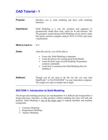
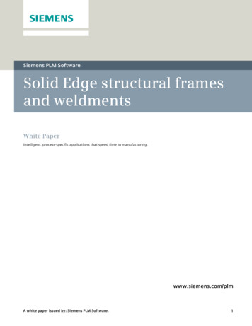
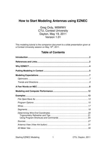
IEEE Transactions on Dielectrics and Electrical InsulationVol. 20, No. 4; August 20131153Design and Modeling of Nanocrystalline Iron Core ResonantTransformers for Pulsed Power ApplicationsAndrew H. Seltzman, Paul D. Nonn and Jay K. AndersonUniversity of Wisconsin - MadisonDepartment Physics1150 University AveMadison, WI 53706, USAABSTRACTA high power resonant three phase switch mode power supply has been constructed atUniversity of Wisconsin to drive a klystron tube. Utilization of a resonant transformer withloosely coupled secondaries allows generation of high boost ratios exceeding the turns ratiowhile providing high efficiency. Use of nanocrystalline iron cores provides high volt secondswhile maintaining low loss at high switching frequencies. Analytic models are developed andcompared to measured data from two different size resonant transformers and effects ofturns ratio, load resistance, and primary are examined and compared to theory.Index Terms — Resonant power conversion, resonators, HF transformers, voltagetransformers, power systems, klystrons, pulse generation, pulse width modulated powerconverters, pulse width modulated inverters, pulse width modulation, DC-DC powerconversion, power conversion, power conversion harmonics1 INTRODUCTIONPOLYPHASE resonant power converters are a newmethod to generate high voltages with high power whilemaintaining a small physical size of 10 times smaller thanprevious methods. Such power converters are capable ofproducing 10s of MWs at 100s of kV. Additional benefitsinclude inherent fault tolerance; the power converter must bedesigned to be matched to a given load such that in the eventof a fault, the resonant circuit will be de-Qed therebypreventing power transfer. In the event of an arc fault, thesystem can safely run through the fault without damage to theload or supply, while the reduction in power transfer may besufficient to clear the arc fault. Resonant power converterswith nanocrystalline iron cores maintain the high permeabilityof iron cores, while allowing efficient use at higherfrequencies in the 10s of kHz usually reserved for ferritematerials. Consequently, a nanocrystalline transformer canprovide 300 times the power transfer capability as a 60 Hztransformer for a given size and weight. For comparison, a100 kV, 60 Hz system carrying 20 Arms and utilizing soft ironcores will be on the scale of 35 tons and have about 30 kWlosses while the transformer in a polyphase resonant converteroperating at 140 kV and 20 kHz carrying 20 Arms utilizing ananocrystalline core will weigh 200 kg and have about 3 kWof losses. Efficiency of as high as 97% may be realized withsuch a system [1]. Such resonant systems can achievesignificantly greater power levels with a given set of powerelectronics in part to the resonant nature of the secondaryManuscript received on 30 September 2012, in final form 7 March 2013.which allows soft switching thereby reducing junction heatingin the IGBTs. Given the exact nature of the system, either zerovoltage switching or zero current switching may be utilized byswitching the IGBTs during the period of reversecommutation of the anti-parallel diodes in the IGBT module,or by operating near resonance such that the IGBTs switchnear the zero crossing period of primary current [2, 3].The use of resonant circuits in high voltage switchingpower converters allows the voltage boost ratio of thetransformer to exceed the turns ratio, resulting in morecompact designs, as shown in Figures 1 and 2, and reductionof copper usage in the secondary winding.Figure 1. Three phase resonant power supply.1070-9878/13/ 25.00 2013 IEEE
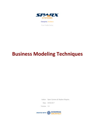
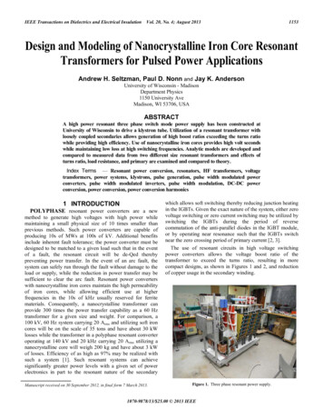
1154A. H. Seltzman et al.: Design and Modeling of Nanocrystalline Iron Core Resonant Transformers for Pulsed Power ApplicationsThe strong dependence of the boost ratio on switchingfrequency allows the power supply to regulate output voltage byshifting switching frequency. By switching at full duty cyclenear resonance, the primary voltage and current are in phase,allowing for zero current switching (ZCS), and significantreduction of switching losses. As switching frequency movesaway from resonance, the IGBT current at the switching eventsincreases from zero, however with only two switching eventsper cycle, switching losses remain low [4-6].Figure 2. Resonant power supply transformers.Additional benefits of resonant topologies include thestrong dependence of power transfer on a matched outputload; in the event of a short circuit, the resonant circuit will bede-Qed and power transfer will automatically reduce withoutdamage to the supply or klystron load [7-10].The construction of such a power supply required thedesign of a suitable resonant transformer system utilizing ananocrystalline core. Initially, a time consuming trial anderror approach of transformer design was utilized to find theoptimum turns ratio, involving the production of multiplesecondaries with varying numbers of turns. Subsequently thedata gathered from the multiple transformer designs wasused to develop and validate numerical and analyticalmodels of resonant transformers which may be used forfuture designs.2 RESONANT TRANSFORMERCHARACERISTICSIn contrast to closely coupled inductive systems, such as atightly wound transformer with low leakage inductance,loosely coupled transformers provide a high leakageinductance that may be used to form a resonant circuit. Inmany cases efficient power transfer may only be attained ifeither or both the primary and secondary windings arecapacitively compensated. In closely coupled reactive powersystems, the reactive power is usually less than the real powertransferred, while in certain loosely coupled systems, thereactive power can be up to 50 times the real power [11]. Highleakage inductance is achieved by designing the secondarywinding with a large private magnetic flux.For use in high power density switching power supplies, acore material with high volt seconds and low loss must beused. Soft iron cores have unacceptably high loss due to theirlarge lamination thickness and magnetic properties leading toeddy current and hysteresis losses, respectively. Ferrite coresoperate efficiently at high frequency, but saturate at lowmagnetic flux, limiting the volt seconds per turn that may becarried by the core. The use of nanocrystalline or amorphouscores allows for high saturation flux providing adequate voltseconds per turn for high power density applications whileproviding low losses at high frequency [12-14].Resonant transformers for klystron power supplyapplications have traditionally been designed with a tightlywound, low impedance primary made of either a copper strapwinding or Litz wire. The secondary is loosely wound togenerate a large private magnetic flux and achieve thenecessary leakage inductance. A resonator capacitor is placedin parallel with the secondary and the inductance andcapacitance are tuned to achieve the desired resonantfrequency and boost ratio.Further benefits of resonant transformers include reductionof switching harmonics. While a non-resonant transformerwill couple higher harmonics from a square wave input intothe secondary, a resonant system will only couple them at theturns ratio, while only the fundamental harmonic will bepassed at the boost ratio, providing a sinusoidal waveform tothe rectifier. This can reduce switching harmonics by a factorof the (boost ratio) / (turns ratio) which is routinely on theorder of 10:1.3 RESONANT TRANSFORMER DESIGNTwo transformer designs are presented, one “large coreresonant transformer” for use on the power supply with a63mm width by 44mm depth core cross section and a 114mmwidth by 228 mm height window area utilizing ananocrystalline “Namlite” core, and a “small core resonanttransformer” for further testing of analytic models with a 25mm by 25 mm core cross section and a 100 mm by 100mmwindow area utilizing an amorphous “Metglas” 2605SA1core. The small core transformer was tested with both lowresistance and high resistance primary windings to evaluatethe effect of primary resistance on transformer resonance.Both transformers examined herein have a parallel pair of 10turn primary windings on each leg of the C-core and a parallelpair of secondaries. All quoted leakage inductance is theinductance of the two secondaries in parallel.Figure 3. Large core resonant transformer.
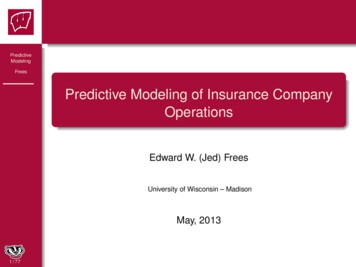
Vol. 20, No. 4; August 2013140[1][2][3][4][5][6][7][8][9]120100Boost Ratio3.1 LARGE CORE TRANSFORMER TESTINGA set of three transformers, as shown in Figures 3 and 4,with loosely coupled resonant secondaries are used to drivethe klystron tube through a doubling rectifier.Each transformer is built around a nanocrystalline iron corethat allows low loss operation at high switching frequencieswhile providing a high saturation flux when compared toferrite materials. The primaries consist of a parallel pair of 10turn copper strap coils, wound around a polycarbonate formand held in close proximity to the cores. Each winding used a0.8 mm thick, 12.5 mm wide copper strap, wound in a helicalmanner around a 6.4 mm thick polycarbonate coil form. Thesecondaries consist of a parallel pair of 165 mm diameter,136turn coils made out of 0.68 mm diameter solid enamel coatedwire and have a parallel 50 nF capacitor resonator. For addedcurrent handling capability, each secondary consists of twolayers of wire, connected in parallel at the ends of thewindings and separated by Mylar insulation. Individual oiljackets enclose each secondary as shown in Figure 4;providing insulation, cooling and preventing corona dischargeon the windings. Further suppression of corona discharge isaccomplished by grounding the cores to prevent chargebuildup and placing a faraday screen consisting of conductivecopper tape on the inside surface of the secondary oil tank toprevent displacement current from the windings fromcapacitively coupling to the core or surrounding air.1155Frequency Responce of Boost Ratio at Varying Turns Ratiofor 165 mm Diameter Secondary Windings with a 1.8k Ohm Load801:N 15.61:N 14.61:N 13.61:N 12.61:N 11.61:N 10.61:N 9.61:N 8.61:N 7.6[1][2][3][4] [5][6][7][8][9]604020005101520Frequency (kHz)253035Figure 5. Boost ratio for the large core resonant transformer with a 1.8k ohmload.Frequency Responce of Boost Ratio at Varying Turns Ratiofor 165 mm Diameter Secondary Windings with a 820 Ohm Load70[1][2][3][4][5][6][7][8][9]6050Boost RatioIEEE Transactions on Dielectrics and Electrical Insulation401:N 15.61:N 14.61:N 13.61:N 12.61:N 11.61:N 10.61:N 9.61:N 8.61:N 7.6[1][2] [3][4][5][6][7][8][9]302010005101520Frequency (kHz)253035Figure 6. Boost ratio for the large core resonant transformer with an 820load.Analytical and numerical models for the transformer’stransfer function were derived and compared to measureddata. The final version of the transformer was chosen to havea 136 turn secondary, a primary leakage inductance of 8 µH, aprimary magnetizing inductance of 1.69 mH, a secondaryreferred total leakage inductance of 1.36 mH, a primary seriesresistance of 27.3 m , and a secondary series resistance of 1.2. A spice model of the transformer is presented in Figure 7.Figure 4. Large core resonant transformer assembly diagram.Figure 7. Full transformer model for large core transformer.The final transformer design was obtained through trial anderror, testing secondary windings with 76 through 156 turnsuntil a final design with suitable inductance for the desiredresonant frequency and maximum boost ratio was obtained, asshown in Figures 5 and 6.A simplified model of the transformer may be obtained byapproximating that the magnetizing inductance is infinite,which remains valid as long as the transformers are runwithout saturating the cores, that primary resistance andleakage inductance is negligible, and that the cores are
1156A. H. Seltzman et al.: Design and Modeling of Nanocrystalline Iron Core Resonant Transformers for Pulsed Power Applicationsmagnetically lossless. The system may then be modeled as aresonant LC tank circuit driven by a voltage equal to theprimary voltage times the turns ratio as shown in Figure 8.model consisting of a voltage source of N times the primaryvoltage connected across a resonant circuit including aninductor of finite ESR with inductance calculated from theWheeler compensated area formula, and an ideal capacitorwith a load resistor connected in parallel across the capacitoras shown in equation (2).VsecV priNRinductor11Rloadj Lres(2)j CresThe resulting transfer function predicts the boost ratio ofthe transformer over the desired frequency range to reasonableaccuracy as shown in Figure 10.Comparison of Measured and Analytical Models of Boost Ratiofor 165 mm Diameter Secondary Windings with a 1.8k Ohm Load140Figure 8. Simplified transformer model for large core transformer.1:N 13.6 Measured1:N 13.6 Transfer Function120An analytical model for the inductance of a loosely coupledtransformer was obtained by modifying the Wheeler formulafor a short solenoid [15] to obtain leakage inductance.Assuming an ideal model of the transformer where magneticflux is entirely excluded from the core and primary of thetransformer when the primary is shorted, the Wheeler formulais modified by subtracting the total core cross sectional area,denoted “Acore”, from the cross sectional area of thesecondary winding as shown in equation (1) where “r” is coilradius, “h” is coil height, and “Acoil” is coil area.Lwheeler102Acoil0NAcore(1)9rcoil 10hcoilThe resulting formula, called the “Wheeler compensatedarea” formula herein, predicts the leakage inductance of thetransformer with high accuracy when compared to theWheeler formula without area compensation and the longsolenoid approximation as shown in Figure 9.-33.5x 10Comparison of Measured and Analytical Models ofWinding Leakage Inductance for a 165 mm Diameter Secondaries[1][2][3][4][5]Boost Ratio806040200051520Frequency (kHz)253035The boost ratio at resonance for two different loadresistances is shown in Figure 11. As seen in Figure 10, theboost ratio predicted by the analytical formula is consistentlyhigher than the measured values. Note that the model usingequation (2) uses the DC resistance of the secondary and doesnot include skin effects or finite primary resistance which maycontribute to the overshoot of the predicted boost ratio atresonance when compared to experimental data.[4]Comparison of Measured and Analytical Models of Resonant Boost Ratiofor 165 mm Diameter Secondary Windings with 1.8k and 820 Ohm urns Ratio (1:N)1314R 1.8k ohmR 1.8k ohmR 820 ohmR 820 ohmMeasuredTransfer FunctionMeasuredTransfer Function[2][1]1.50.510Figure 10. Measured and analytical models of boost ratio for the large coretransformer.Resonant Boost RatioLeakage Inductance (H)3MeasuredWheeler Compensated AreaWheeler Full AreaLong SolenoidLong Solenoid Compensated Area100151201008016Figure 9. Measured and analytical models of secondary winding leakageinductance for the large core transformer.[4]6040An analytical model of the transformer’s transfer functionwas developed and compared to experimental data. Thetransformer model may be simplified to a secondary referred[3]789101112Turns Ratio (1:N)13141516Figure 11. Measured and analytical models of boost ratio at resonance forvarying turns ratio for the large core transformer.
IEEE Transactions on Dielectrics and Electrical InsulationVol. 20, No. 4; August 2013The resonant frequency of a RLC circuit with the load resistancein parallel with the capacitance [16] is given in equation (3).12Fres1Lres Cres1Rload Cres(3)2When the value of inductance from the Wheeler compensatedarea formula is used the predicted resonant frequency matchesthe measured value as seen in Figure 12.1157are not affected to any great extent by scaling of thetransformer size. The secondaries consist of a parallel pair of102 mm diameter windings with a secondary series resistanceof 0.9for the 90 turn version. Further, two separateprimaries, one with a 2.5 m ESR, denoted “Low R” and theother with a 48 mOhm ESR, denoted “High R”, as shown inFigure 16 were used to determine the effect of primaryresistance on transformer performance.Comparison of Measured and Analytical Models ofResonant Frequency for 165 mm Diameter Secondary Windings32MeasuredTransfer Function30Resonant Frequency (kHz)28262422201816789101112Turns Ratio (1:N)13141516Figure 12. Measured and analytical models of resonant frequency as afunction of turns ratio for the large core transformer.Figure 14. Small core resonant transformer.As the load resistance is varied while the transformer is drivenat resonant frequency, the boost ratio varies as shown inFigure 13. The transfer function model of the transformeraccurately predicts the boost ratio over a wide range of loadresistances. The knee at high load resistances is due to thefinite resistance of the inductor limiting the maximumattainable boost ratio.Responce of Boost Ratio at Resonance to Varying Load Resistacefor 165 mm Diameter Secondary Windings3101:N 15.6 Measured1:N 13.6 Measured1:N 7.6 Measured1:N 13.6 Transfer Function2Resonant Boost Ratio10110010-110-210010110231010Parallel Load Resistance (ohms)410510Figure 13. Measured and analytical models of boost ratio at resonance forvarying load resistance for the large core transformer.3.2 SMALL CORE TRANSFORMER TESTINGA small resonant transformer utilizing an amorphous“metglas” core, as shown in Figures 14 and 15, wasconstructed and tested to verify that the analytical formulasFigure 15. Small core resonant transformer assembly diagram.Boost ratio for the small core transformer was measured forboth Low R and High R primary windings. It was shown that theincrease in primary resistance incurred by using a small gaugewire significantly degraded the performance of the resonantcircuit, particularly for high turns ratios as shown in Figure 17.
1158A. H. Seltzman et al.: Design and Modeling of Nanocrystalline Iron Core Resonant Transformers for Pulsed Power ApplicationsThe higher resistance primary greatly reduces the boostratio, and increases secondary leakage inductance leadingto a lower boost ratio and resonant frequency as shown inFigures 19 and 20. The higher effective leakageinductance is due to the higher resistance primary’sinability to effectively screen magnetic flux from thesecondary winding out of the transformer core. Thecurrent driven in the primary is dissipated by theresistance leading to a lower Q circuit and lower boostratio at resonance. The high Q of the transformer with theLow R winding leads to difficulties measuring the peakboost ratio values, leading to the lower measured boostratios for high turns ratios seen in Figure 20. Resonantfrequency is measured and compared to the analyticalmodel in Figure 21.Figure 16. Low R and High R primary windings.Frequency Responce of Boost Ratio at Varying Turns Ratiofor 102 mm Diameter Secondary Windings with a 1kOhm LoadComparison of Measured and Analytical Models of Boost Ratiofor 102 mm Diameter Secondary Windings with a 1kOhm Load120[1] 1:N 8 Low R Primary[2] 1:N 6 Low R Primary[3] 1:N 4 Low R Primary[4] 1:N 2 Low R Primary[5] 1:N 1 Low R Primary[6] 1:N 8 High R Primary[7] 1:N 6 High R Primary[8] 1:N 4 High R Primary[9] 1:N 2 High R Primary[10] 1:N 1 High R Primary[2]Boost Ratio80[3]60140100[4]40[6][7] [8]20[1] 1:N 8 Measured Low R Primary[2] 1:N 8 Measured High R Primary[3] 1:N 8 Transfer Fcn120Boost ency (kHz)[2]0Figure 17. Boost ratio for the small core resonant transformer with a 1 kload for Low R and High R primary windings.While the analytical model accurately predicts leakageinductance for the low resistance Low R winding, the higherresistance High R winding diverges from the predictionparticularly at high turns ratios as shown in Figure 18.Leakage Inductance (H)54[5]405060100[6][2]330Frequency (kHz)[1] 1:N 8 Measured Low R Primary[2] 1:N 8 Measured High R Primary[3] 1:N 8 Transfer Function120Measured Low R PrimaryMeasured High R PrimaryWheeler Compensated AreaWheeler Full AreaLong SolenoidLong Solenoid Compensated Area20Comparison of Measured and Analytical Models of Resonant Boost Ratiofor 102 mm Diameter Secondary Windings with a 1kOhm Load140Comparison of Measured and Analytical Models of-4x 10 Winding Leakage Inductance for 102 mm Diameter Secondaries[1][2][3][4][5][6]10Figure 19. Measured and analytical models of boost ratio for the smallcore transformer with a 1k ohm load for Low R and High R primarywindings.Resonant Boost Ratio60[4][1][3]280[1]60[3]40[2]201012345Turns Ratio (1:N)678Figure 18. Measured and analytical models of secondary winding leakageinductance for the small core transformer.012345Turns Ratio (1:N)678Figure 20. Measured and analytical models of boost ratio at resonance forvarying turns ratio for the small core transformer.
IEEE Transactions on Dielectrics and Electrical InsulationVol. 20, No. 4; August 2013Comparison of Measured and Analytical Models ofResonant Frequency for 102 mm Diameter Secondary WindingsREFERENCES140Resonant Frequency (kHz)[1]Measured Low R PrimaryMeasured High R PrimaryTransfer Function120100[2]8060[3]40[4]20012345Turns Ratio (1:N)6711598[5]Figure 21. Measured and analytical models of resonant frequency as afunction of turns ratio for the small core transformer.[6]4 DESIGN CONSIDERATIONS[7]When designing a high voltage resonant transformer,several considerations must be taken into account. Atresonance the primary will be carrying a very large currentat high frequency. For proper modeling and goodperformance of a resonant transformer, it is necessary toensure low primary resistance to completely screen outprivatized secondary magnetic flux from the core. The useof Litz wire on the primary, or independently insulatedlayered copper straps will decrease skin effect inducedresistance at high frequencies and greatly improveperformance.For the analytical models presented herein, the DCresistance of the secondary is used and does not includeskin effects or finite primary resistance which maycontribute to the overshoot of the predicted boost ratio atresonance when compared to experimental data. The use ofa low resistance primary will ensure accurate modeling oftransformer performance.[8][9][10][11][12][13]5 CONCLUSIONThe use of the analytical models presented in this paper willallow rapid design of loosely coupled transformers without theuse of time consuming trial and error methods by providingaccurate predictions of leakage inductance, resonantfrequency, maximum boost ratio, and transfer function shape.For accurate modeling of resonant transformers and optimumperformance, it is imperative to keep primary windingresistance low.ACKNOWLEDGMENTThe authors thank Los Alamos National Lab for donatingcomponents to the project and William A Reass fordeveloping the precedent of using resonant boost in klystronpower supplies. This work is supported by the Department ofEnergy (DOE), USA.[14][15][16]W.A. Reass, D.M. Baca, R.F. Gribble, D.E. Anderson, J.S. Przybyla,R. Richardson, J.C. Clare, M.J. Bland and P.W. Wheeler, "HighFrequency Multimegawatt Polyphase Resonant Power Conditioning",IEEE Trans. Plasma Sci., Vol. 33, No. 4, pp.1210-1219, 2005.W.A. Reass, D.M. Baca, M.J. Bland, R.F. Gribble, H.J. Kwon, Y.S.Cho, D.I. Kim, J. McCarthy and K.B. Clark, "Operations of polyphaseresonant converter-modulators at the Korean Atomic Energy ResearchInstitute", IEEE Trans. Dielectr. Electr. Insul., Vol. 18, No. 4, pp.1104-1110, 2011.W.A. Reass, J.D. Doss and R.F. Gribble, “A 1 megawatt polyphaseboost converter-modulator for klystron pulse application”, PulsedPower Plasma Science (PPPS), Vol. 1, pp. 250–253, 2001.D.M. Divan and G. Skibinski, "Zero-switching-loss inverters for highpower applications", IEEE Trans. Industry App., Vol. 25, No. 4, pp.634-643, 1989.G. Hua and F. C. Lee, "Soft-switching techniques in PWMconverters," IEEE Trans. Indust. Electronics, Vol. 42, No. 6, pp. 595603, 1995.M. J. Bland, J. C. Clare, P. Zanchetta, P.W. Wheeler and J.S.Pryzbyla, "A high frequency resonant power converter for highpower RF applications", European Conf. Power Electronics andApplications, pp. P.1-P.10, 2005.W.A. Reass, D.M. Baca, J.D. Doss and R.F. Gribble, "Designtechnology of high-voltage multi-megawatt polyphase resonantconverter modulators", IEEE Industrial Electronics Soc. (IECON),29th Annual Conf., Vol. 1, pp.96-101, 2003.W.A. Reass, J.D. Doss, M.G. Fresquez, D.A. Miera, J.S. Mirabal andP. J. Tallerico, "A proof-of-principle power converter for theSpallation Neutron Source RF system", Particle Accelerator Conf.,Vol. 1, pp. 426-428 1999W.A. Reass, D. L. Borovina, V.W. Brown, J.D. Doss, R.F. Gribble, T.W. Hardek, M.T. Lynch, D.E. Rees, P.J. Tallerico and D.E. Anderson,"The polyphase resonant converter modulator system for theSpallation Neutron Source linear accelerator", 25th Int’l. PowerModulator Sympos., pp. 684-688, 2002.D.E. Anderson, J. Hicks, M. Wezensky, D. Baca and W.A. Reass,"Operational Performance of the Spallation Neutron Source HighVoltage Converter Modulator and System Enhancements", 27th Int’l.Power Modulator Sympos., pp. 427-430, 2006.O.H. Stielau and G.A. Covic, "Design of loosely coupled inductivepower transfer systems", Int’l. Conf. Power System Technology(PowerCon), Vol. 1, pp. 85-90, 2000.Z.M. Shafik, K.H. Ahmed, S.J. Finney and B.W. Williams,"Nanocrystalline cored transformer design and implementation for ahigh current low voltage dc/dc converter", 5th IET Int’l. Conf. PowerElectronics, Machines and Drives (PEMD), pp. 1-6, 19-21 2010.T. Filchev, F. Carastro, P. Wheeler and J. Clare, "High voltage highfrequency power transformer for pulsed power application", 14thInt’l. Power Electronics and Motion Control Conf., pp. T6-165,T6170, 2010S. Wei, W. Fei, D. Boroyevich and C.W. Tipton, "High-DensityNanocrystalline Core Transformer for High-Power High-FrequencyResonant Converter", IEEE Trans. Indust. Appl., Vol. 44, No. 1, pp.213-222, 2008.H.A. Wheeler, "Formulas for the Skin Effect", Proc. IRE , Vol. 30,No. 9, pp. 412-424, 1942.K.L. Kaiser, Electromagnetic Compatibility Handbook, CRC Press,pp5.25-2.56, 2004.Andrew H. Seltzman (M’12) was born in Raleigh,North Carolina in 1985. He received the B.S.degrees in physics and electrical engineering fromthe Georgia Institute of Technology, Atlanta,Georgia, USA in 2008, and the M.S. degree inelectrical engineering from the University ofWisconsin, Madison, in 2012. He is currently at theUniversity of Wisconsin, working on a Ph.D. inplasma physics with a focus on RF heating andcurrent drive on Madison Symmetric Torus. Mr. Seltzman is a member of theAmerican Physical Society, division of plasma physics.
1160A. H. Seltzman et al.: Design and Modeling of Nanocrystalline Iron Core Resonant Transformers for Pulsed Power ApplicationsPaul D. Nonn began working at the University ofWisconsin as an undergrad student technician in1961 on the first plasma experiment at UW, thelinear quadrupole and continued through theevolution of three octopoles, culminating in thelevitated octopole experiment focusing on pulsingradar magnetrons for unprecedented long pulsesfor ECH startup and developing HV pulsers. Hesubsequently worked in the nuclear engineering department on Phaedrus A, Band tokamak experiments until 1998. He worked for one year for Mik Physicson the development of a novel 100 kW plasma deposition power supplybefore returning to work at the University of Wisconsin. Since then he hasworked on small aspect ratio tokamaks dealing with HV capacitor bank andhigh current circuitry design, finally returning to the physics department todevelop the oscillating field current drive ignitron oscillator on MadisonSymmetric Torus and the electron cyclotron heating klystron power supply.Jay K. Anderson received the M.A. and Ph.D.degrees in physics and the M.S. in electrical andcomputer engineering from the University ofWisconsin, Madison. He has been a scientist at theUniversity of Wisconsin for 15 years, primarilystudying the physics of fusion relevant plasmas inthe Madison Symmetric Torus. His primary interestsare advanced control techniques of the reversed fieldpinch plasma, including heating and current drive by injection of neutralbeams or microwaves. Dr. Anderson is a member of the American PhysicalSociety, division of plasma physics.
Design and Modeling of Nanocrystalline Iron Core Resonant Transformers for Pulsed Power Applications Andrew H. Seltzman, Paul D. Nonn and Jay K. Anderson University of Wisconsin - Madison Department Ph