Transcription
How to Start Modeling Antennas using EZNECGreg Ordy, W8WWVCTU, Contest UniversityDayton, May 19, 2011Version 1.01This modeling tutorial is the companion document to a slide presentation given ata Contest University session on May 19th, 2011.Table of ContentsIntroduction .2References and Links.2Why EZNEC? .4Putting Modeling in Context .5Modeling Expectations .7Optimizers .7Trends and Directions .8A Few Words on NEC .8Modeling and Computer Performance .12Examples .13File Open/Save As .13Program Options .15Wires .17Segments .18Determining Wire End Coordinates .20Trigonometry Refresher and Tips .21Using Program Shortcuts and Commands .23Sources .27Antenna View (View Ant button).3140 Meter Vee.34Starting EZNEC Modeling1CTU, Dayton, 2011
L Networks – 160 Meter Vertical .39Transformers – Flag Antenna and Array .64Flag Antenna Array.75RDF – Receiving Directivity Factor.94Checks and Tests .96Segmentation Check .97Geometry Check .97Model Convergence Test .97Average Gain Test .99Conclusion .105IntroductionThe target audience for this material is the antenna enthusiast who has antennaknowledge and experience, but has thus far avoided integrating modeling intotheir design and thinking process.Modeling has its own terminology, jargon, rules, quirks, tricks, guidelines,restrictions, limitations, and frustrations. Some aspects of antenna modeling areimmediately familiar to a person with antenna design experience. Other aspectstake time to understand, appreciate, and master.A number of very good modeling tutorials and practical model examples existand the ones that I am aware of will be listed in the next section. The approachtaken here will be to go into painful detail in the running of the EZNEC programwhile assuming a moderate level of general antenna knowledge.As with so many activities in life, it often comes down to working through a fewexamples, and getting past those pesky hurdles. My hope is that some of theseexamples and background information will provide illumination on that initialjourney. If you have any questions or comments about the material in thisdocument, I can be reached by email at ordy@seed-solutions.com.Although I’ve never made a single contact on an antenna model, I would notwant to design or install an antenna without at least a quick check of a model tohelp frame my expectations and crosscheck my measurements.References and LinksStarting EZNEC Modeling2CTU, Dayton, 2011
The EZNEC 1 software, created and marketed by Roy Lewallen, W7EL, can beobtained from www.eznec.com. The package comes with a number of examplemodels, and there is an extensive indexed Help 2 facility with information on allaspects of the program. The version used in this document is EZNEC V5.0.The name that many people associate with modeling is L.B. Cebik, W4RNL (SK).L.B. wrote extensively about modeling and modeling tools. Although now a silentkey, L.B.’s personal web site remains at www.cebik.com. His work at that site isnow maintained by AntenneX, www.antennex.com. It is necessary to register toaccess the site, but there is no fee involved. It is well worth it to register and readthrough the many pages.Antennex, at www.antennex.com, maintains a large amount of antenna andantenna modeling information. Although they have an online journal that has asubscription cost, there is also a guest section that is free. It does appear as iftutorial or teaching material created by W4RNL has been placed in products withfees. If you register as a guest at Antennex.com you can access a large numberof articles, including models and descriptions of models.From time to time the ARRL appears to offer an online course on antennamodeling that was written by L.B. Cebik. Over the years, many articles haveappeared in QST and QEX that refer to antenna modeling. Some links can befound on this page: http://www.arrl.org/antenna-modeling.The ARRL Antenna Book makes frequent reference to modeling, and many ofthe models presented in the book are included on the CD that comes with thebook. The most recent 21st edition includes a free version of EZNEC, calledEZNEC-ARRL. Although that might sound appealing, it appears to be nothingmore than a frozen-in-time version of the free version of standard EZNEC, andversion 3 at that. For normal modeling, the 20 segment limit applies. That limitcan be exceeded for the model files provided with the book. As best as I can tell,it’s probably better to just download the most recent free EZNEC, unless modelsincluded with the book are of particular interest.Chapter 4 of the ARRL Antenna Book is titled: Antenna Modeling & SystemPlanning, and contains very useful background information including a modelingpackage comparison as well as a good tutorial.In the most recent and last (5th) edition of ON4UN’s Low-Band DXing, JohnDeveldere, ON4UN, has supplied most all of the models used in the book on theCD that is included with the book. They are EZNEC models. Chapter 4 of thebook is on the topic of Antenna Design Software, and includes a history ofmodeling as well as additional references and links.12EZNEC is a registered trademark of Roy W. Lewallen.The EZNEC programs and Help manual are copyright 2000-2007, Roy W. LewallenStarting EZNEC Modeling3CTU, Dayton, 2011
Dan Maguire, AC6LA, has an interesting web site (www.ac6la.com ) with anumber of programs that work in conjunction with modeling software. A lot ofDan’s work deals with transmission lines, and he is a true expert in that area. Ifyou have transmission lines issues, from theory through practice, talk to Dan.Rudy Severns, N6LF, (http://www.antennasbyn6lf.com) is a frequent author andcontributor to amateur radio publications. Rudy’s work is highly regarded, and hebacks up his work with models and/or measurements. He often uses modeling inhis work, and his site covers a number of interesting and contemporary topics.The modeling package 4nec2 (http://home.ict.nl/ arivoors) is free, and has anumber of users and followers. One interesting feature that it has is the ability toread EZNEC files and run them, as well as create NEC input decks from theEZNEC model. From time to time, this can be quite handy, especially if you findyourself starting to use several different modeling packages. Some featuresintroduced with EZNEC version 5 are not currently supported and can not betranslated and simulated. These include features such as Virtual Wires,transformers, and lossy transmission lines.The Wikipedia has an article about the history of the NEC engines at:http://en.wikipedia.org/wiki/Numerical Electromagnetics Code.Although more about the engine than modeling with the engine, the NEC-2unofficial home page is located at: www.nec2.org.Finally, it never hurts to simply search the Internet for models related to aparticular antenna design. Although there are no guarantees of quality, there is alot of information out in cyberspace, much of it very good.There are many authors who have written on the topic of modeling, and theyshould be included on any useful list. I apologize to those I have omitted, andplease feel free to contact me and I will update this list.Why EZNEC?The various forms of the EZNEC3 product family are probably the most popularmodeling packages used by the amateur radio community. At the entry level,there is a free package with all of the features of the commercial version, butlimited in the complexity of the model.The examples in this document were simulated with the EZNEC V5.0 package.3www.eznec.comStarting EZNEC Modeling4CTU, Dayton, 2011
In some cases, the information will be very specific to EZNEC, and you shouldnot expect to see the identical behavior in other antenna simulators. After all, thisis a tutorial about modeling with EZNEC, not general modeling.EZNEC and other similar antenna modeling packages, with few exceptions, arewrappers for the NEC (Numerical Electromagnetics Code) engines. Theseengines date back to the 1970’s, and were written in Fortran to run on mainframecomputers. Going along with that era, these programs accept input in the form ofa punched card deck, and the outputs are a large text file full of numbers suitablefor printing on a line printer, with fan fold 14” wide tractor feed paper.EZNEC does a lot of work on our behalf to hide all of that mess, and let us workwith a contemporary GUI with many powerful features.Many of the concepts, terminology, and jargon used in EZNEC and similarprograms come from NEC. This is good news because this means that once youlearn one NEC-based program, you can usually pick up others quite quickly.Each NEC shell or wrapper has its own strengths and weaknesses, and don’t besurprised if you collect several as the years go by.Since the NEC engines are ancient in terms of computer evolution, they mightseem to be static, out of data, and maybe even falling behind. In some ways,they are! I don’t believe that the core engines have been officially enhanced indecades. Fortunately, modeling tools can continue to advance by building uponfeatures long present in NEC but unused or at least underused.Just because NEC is effectively frozen in time, don’t think that NEC-based toolsare – they are not.If you tried modeling several years ago, and were frustrated by not finding somecapability, it may be time to check again.Putting Modeling in ContextI think of modeling as one part of a three part approach to successful antennadesign and implementation. The three parts are: Theory (Math)ModelingMeasurementsEach of these can be used to drive a design process, but they also serve tocrosscheck each other. The idea is to create a solid and broad base thatprovides results we can be confident in. I sometimes think of “theory” as “math”,so that I can remember the 3M’s.Starting EZNEC Modeling5CTU, Dayton, 2011
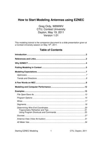
If traditional antenna theory says that the impedance of a half wavelength dipolein free space is around 72 Ohms at resonance, and a model taking into accountthe wire diameter and the height about ground reports 65 Ohms, and themeasured value is 61 Ohms, we can be more confident that we have built a formof what we modeled, and what is close to a textbook half wavelength dipole. Ifthe model reports 150 Ohms, we might want to double check the model. If wemeasure 40 Ohms, then we need to check the measurement device and themodel, and even wonder if we are applying the correct textbook expectations.As part of comparing models and measurements, I always try to check thetracking across the band, as well as data at a single frequency. The problem withdata at a single frequency is that it can accidentally create a false sense ofsecurity. As the saying goes: even a stopped clock is right twice a day.Consider the following two example SWR comparisons between a model and ameasurement.SWRSWRFFIf all we measured was the SWR at a single frequency, F, then we might thinkthat the antenna on the left (blue) matches the model (red) much more closelythan the antenna on the right. If we step back and look at a wider sweep, it’sclear that the left antenna measurements look nothing like the model; except forthe accident that the SWR is the same at the one frequency we happened tocheck. Although I used SWR in this example, the parameter might beimpedance, gain, front to back ratio, or any useful characteristic of an antenna.As I model an antenna, I’m always on the lookout for signatures and trends incharacteristics that can also be measured or observed in the field. In the aboveexample on the right, we see that there are two frequencies where the SWRcurve changes slope. If I can find those in my measurements, and they are closeto where they are expected, then I’m more confident in my implementation. Insome cases, these sorts of signatures are found outside of the formal bandedges.Starting EZNEC Modeling6CTU, Dayton, 2011
Modeling ExpectationsOptimizersModeling with EZNEC tends to be more what if as opposed to find me theanswer. As an example, let’s say that we want to determine the length of a 40meter dipole made from #12 copper wire with the ends at 35 feet high and thecenter at 45 feet. The target frequency is 7.150 MHz, where we want thereactance to be zero Ohms.With EZNEC, you answer that question by modeling a set of lengths thatconverge on an acceptable answer. You could call that cut and try, or even trialand error.Some folks seem to think that modeling software should provide only the finalanswer, and do it in a single step after the question is appropriately asked.There are indeed programs that provide that approach to modeling. They aregenerally called optimizers. As far as I know, EZNEC is not one of them. It simplyprovides results for the current model, and if you want to alter to model to comecloser to some design goal, you’ll have to make the changes manually and thenrun the model again.My experience has been that except for the most aggressive and complexdesigns, the cut and try approach is more than acceptable. Convergence to thedesign goals usually happens in a few quick steps, and during that processvaluable insight is gained about the design. In the previous example, it might bea sense of how many KHz resonance shifts for each inch of antenna length.That’s certainly good to know if you are actually tuning the antenna out in thefield.If you do anticipate that you might need to run many models (hundreds tothousands) to find the answer, then you might want to consider an optimizer.Even when using an optimizer, some hand modeling is desirable for insight anddeveloping a sense of how the antenna performs in the overall design space andfrequency range.One of the concerns about optimizers is that they converge and stop at a localdesign goal that is not the best in the overall global design space. Havingknowledge about the space is insurance against falling into those traps. I thinkit’s reasonable to say that an experienced modeler will get more out of anoptimizer than a beginning modeling. Even if you want to or need to rely uponoptimizers, it is probably a good idea to become a proficient modeler on yourown.Starting EZNEC Modeling7CTU, Dayton, 2011
Trends and DirectionsI often view modeling as providing answers about trends and directions asopposed to absolute numbers. To highlight this idea, let’s say that I model twovariations of a design, and one reports a maximum gain of 4.0 dBi, and the otherreports 5.2 dBi.What I would take from these results is that the second design has about 1 dBmore gain than the first. To expect the 4.0 and 5.2 dBi gain values to be spot onaccurate in the actual antenna is probably going to lead to disappointment. It’snot because modeling has some flaw or inaccuracy, but rather that modelsalmost never take into account all of the environmental variables that surroundreal antennas in the real world. This is especially true as the antenna becomescloser to ground.In comparing designs, I usually think in terms of words like more or less, higheror lower, or narrower or wider. In other words, I’m looking at the relativedifferences between antennas, not absolute gain, front to back ratio, RDF,bandwidth, or other antenna characteristics.An exception would be impedance, where we might be targeting specific valuessuch as 50 Ohms. Since impedance is becoming easier and easier to measurewith accuracy, we can double check our results when it matters. Because mosttransmission lines are 50 Ohms, it is important that we come acceptably close.A Few Words on NECAs mentioned earlier in this document, EZNEC, and most all antenna modelingpackages, are based upon a simulation engine family broadly named NEC – theNumerical Electromagnetics Code. This is usually pronounced as neck, and it isnot the same as the National Electrical Code, which is the code that most think ofas being about safe house wiring. It is also not related to the N.E.C. which is theNippon Electric Company.The references provided earlier, especially the Wikipedia page and chapter 4 ofthe ARRL Antenna Book provide detailed historic information.As best as I can determine, NEC-1 does not exist. As you might guess, NEC-2,NEC-3, and NEC-4 are more recent versions, each an update to the previous.NEC-4, the most recent, released in 1992, is now almost 20 years old. NEC-3,although released and used in some products, did not survive.When talking about NEC, there are only two practical choices – NEC-2 and NEC4. As far as I know, NEC-4, in all areas of accuracy, is considered to be superiorto NEC-2. That begs the question, why is NEC-2 still being used?Starting EZNEC Modeling8CTU, Dayton, 2011
NEC-2 has the desirable property that it is free, in the public domain, can bedistributed and used without a software license, and can be used around theworld.NEC-4 still requires a specific software license, and the cost is around 300 atthis time (2011). In addition, there are export restrictions on the engine, so itcannot be sent to certain countries no matter how much money is available.Since NEC-4 is considered to be more accurate, it is often viewed as theprofessional form of NEC, and that means that the wrappers that surround itmight offer more features, and also cost more money. Note that there are twocosts here – the cost of the NEC-4 engine, and the cost of the wrapper software.So, the bottom line is that NEC-2 tools are several hundred dollars lessexpensive than NEC-4 tools, if not free. EZNEC, using NEC-2 for example, has afree version, a version around 90, and a version around 140 (2011 prices).The EZNEC V5.0 that I use is the 140 package. But, if you were to move up tothe versions that can use NEC-4, you are stepping up to a little less than 1000.Other modeling packages with both NEC-2 and NEC-4 price points have asimilar two-tier structure.I think we can now appreciate that unless the NEC-4 features and accuracy areabsolutely needed, or, money is no object, the vast majority of folks doingantenna modeling around the world use NEC-2.When the personal computer arrived on the scene, a new engine was created forthe PC, and it was initially written in Basic as opposed to Fortran. It was calledMININEC. Because it could run on hardware that we could all afford, it wasinitially quite popular. It has been developed and enhanced over the years, andthere are commercial tools that use the MININEC engine.There are areas where MININEC is considered more accurate than NEC-2, andareas where NEC-2 is considered better. So, there are good reasons why bothengines should still exist.Over time, the PC grew into a more capable computing platform, and it waspossible to move the original NEC-2 and NEC-4 mainframe code to the PC.EZNEC, as far as I know, is exclusively based upon NEC-2 and NEC-4. But, theterm MININEC still seems to come up from time to time. That is not a referenceto the MININEC engine, but to a type of ground model that is associated with theMININEC engine, and was then adopted by versions of NEC-2.Starting EZNEC Modeling9CTU, Dayton, 2011
This is a good time to mention what are considered to be the primaryweaknesses in NEC-2. NEC-2 is considered to have two main issues4:1. Modeling tapered elements (stepped diameter), such as made out oftelescoping aluminum tubing.2. Modeling wires that are very close to ground, lying on the ground, orburied in the ground.At first blush, these look like serious problems, since in the case of the firstproblem it is hard to model most Yagi and beam antennas, or any antenna madefrom telescoping aluminum tubing. In the case of the second, it seems hard tomodel a vertical antenna with a ground radial system.Because these are both very common and important types of antennas, NEC-2,at least in EZNEC, has been augmented and enhanced to work around theseproblems.In the case of the telescoping tubing, an algorithm called stepped diametercorrection has been added to EZNEC. This approach converts a set of steppedlengths into a single length that is considered to be equivalent. The actual modeluses the equivalent dimensions, not the original. The details of this approach aredescribed in the EZNEC Help documentation5. I should mention that I recentlyhad the opportunity to work on some very large Yagi designs, and I was able tosee differences between NEC-2 and NEC-4 results for the same model, and toconfirm via impedance measurements that NEC-4 was closer to the measuredvalues. Note that these are feed point impedance differences, which appear to bethe place where the engines mainly diverge. For the casual and even seriousdesigner, NEC-2 with the stepped diameter correction in EZNEC is probablymore than good enough. If you want to be a world class designer of antennaswith stepped diameters, you probably need to spend the money and move up toNEC-4.The issues with modeling ground radials, including buried radials, can also besolved by using NEC-4. If you want to do serious work with ground radialsystems, then using NEC-4 is strongly suggested. If you don’t want to spend themoney, you can still achieve good results using EZNEC/NEC-2. One approach,the one that I use most all of the time, is to select the MININEC-type groundmodel, and then use a series resistor at the base of the antenna to representexpected ground loss. This popular approach that is described in the Helpdocumentation avoids the problem of having to model the ground system at all,and a vertical is not much more than a wire touching the ground with a resistor atthe base. This is especially convenient for modeling vertical arrays, where part of4There are some secondary issues too. For example, NEC-2 has a difficult time modeling verysmall loop structures. The issues presented here tend to come up most often.5And see Physical Design of Yagi Antennas, David Leeson, W6QHS, page 8-18 (available fromthe ARRL)Starting EZNEC Modeling10CTU, Dayton, 2011
the design task is to locate the verticals. Who wants to drag around radial wiresin addition to the verticals in their models?Note, however, that this is the MININEC-type ground in EZNEC, not theMININEC engine.There is at least one more issue that lingers from the days of the early personalcomputers. The NEC engines obviously perform a large number of computationson real or floating point data (as opposed to integer data). At the computerhardware level, there are two popular data formats for representing floating pointdata. One is the 32-bit format that is often called single precision, and the other isthe 64-bit or double precision format. In the early days of PCs (remember theoptional floating point coprocessor chip?), there was a performance and programsize cost to using the double precision format. Double precision programs werelarger and slower.These differences led to the creation of NEC engines that were compiled for thesingle or double precision data representation. While there still might besituations where using single precision makes sense, the advances in computerspeed and capacity largely remove this as an issue. In the case of manyantennas, the difference in precision is not going to be a factor in the results. Still,unless you are forced at gun point to use single precision, use double precisionto gain the higher accuracy potential.If you want to move a model from one package to another, you may have somechoices. One approach that will always work is to simply manually transfer themodel into the new package while looking at the old package model. If there area lot of wires and complexity, this can be tedious and error prone, although italways works.Because the wire definitions are usually the longest part of a model, somepackages have facilities to import and export just the wire portion of the model.This can also be useful if you are generating your wire coordinates through adesign program.Another approach is to see if you can exchange NEC card decks. As mentionedbefore, the NEC engines maintain the abstraction of a deck of punched cards formodels. Some tools let you import or export NEC data. Although EZNECversions other than EZNEC/Pro do not support this, there are still some options.One trick I’ve used from time to time is to work in EZNEC, then import that *.EZmodel file into 4nec2, and then have 4nec2 create a NEC-format card deckimage file. From that point, I can move to any tool that consumes the low levelNEC format.Starting EZNEC Modeling11CTU, Dayton, 2011
Modeling and Computer PerformanceWhen the NEC engines escaped the Fortran mainframe computer and arrived onthe lowly PC, performance and capacity were valid concerns. Do you rememberthe days of magical memory numbers such as 640K, and extended andexpanded memory?The practical impact on models was to encourage the use of the minimumnumber of Wire segments, and to analyze antenna patterns as slices throughsingle azimuth or elevation planes. If you dig out antenna articles6 from that timethat used antenna models, you’ll find references to taking many minutes to run asingle model.Fortunately the dark ages of personal computing did not last too long, and wenow sit in front of demand paged virtual memory machines with multiple coreCPUs running at several GHz with several gigabytes of physical memory7. Thereis very little performance penalty8 in using double precision (64-bit) floating pointcalculations as compared to single precision (32-bit) calculations. File andmemory sizes are rarely an issue.The good news today is that most all antenna models simulated on EZNEC canproduce a full 3 dimensional pattern analysis in just a second or two. Capacity isusually limited by the modeling tool product definition, not the time it takes to sitand wait for a result.While there are times when using too many Wire segments is a bad idea, it is nolonger necessary to waste a lot of time trying to minimize segment count,potentially lowering model accuracy. It’s also possible to quickly produce 3Dpatterns that fully reveal the total pattern, as opposed to single slices that mighthide important details.An aspect of this computer performance bonanza is that it’s now easy to quicklymodel antenna performance across an entire amateur band, not just a singlefrequency. This can reveal nasty performance surprises that can be easilymissed if you are just looking at a single target frequency. Amateur radio issomewhat unique in that antennas, especially transmitting antennas, usuallyfunction across an entire band, not just a single assigned frequency.6Modeling HF Antennas with MININEC – Guidelines and Tips from a Code User’s Notebook: Dr.John Belrose, VE2CY, ARRL Antenna Compendium #3, page 156.7The performance improvement in modeling is at least partly due to improved compilertechnology and some hand optimization of the NEC programs. To the best of my knowledge,folks engaged in these efforts have always tried to preserve the NEC semantics.8I measured a 6% increase in execution time with the double precision as opposed to singleprecision engine for a model sweep that took 3 minutes of wall clock time.Starting EZNEC Modeling12CTU, Dayton, 2011
Designers used to have to settle for modeling an antenna at a single frequencylooking at a few carefully selected azimuth or elevation pattern slices. Now,inspecting and evaluating the full 3D antenna pattern across an entire band is nota big deal.If you tried modeling several years ago, and were frustrated by the practicalcapacity or complexity limits of a model, it may be time to check again.ExamplesIt’s finally time to
Starting EZNEC Modeling 1 CTU, Dayton, 2011 How to Start Modeling Antennas using EZNEC Greg Ordy, W8WWV CTU, Contest University Dayton, May 19, 2011 Version 1.01 This modeling tutorial is the companion document to a slide presentation given at a Contest University sessi