Transcription
FAILURE ANALYSIS OF SAMSUNG NOTE 7JANUARY 23, 2017UL and the UL logo are trademarks of UL LLC 2017
UL & THE SCIENCE OF BATTERY SAFETYUL HAS DEEP KNOWLEDGE IN THE SCIENCEOF LITHIUM-ION BATTERY SAFETY Research staff includes scientists and engineers with backgrounds in materialscience, electrochemistry, mechanical and electrical engineering Research capabilities include failure forensic analysis, internal short circuit(ISC) simulation, thermal electrochemical modeling, aging simulation and others Prior research work includes US National Transportation Safety Board (NTSB)investigation into safety of lithium-ion batteries on airplanes Published 10 standards on battery & energy storage technology safetyConfidential2
SCOPE OF PROJECT – COMPANY APHASE 1All samples provided by SamsungFIELD EVENTSAMPLES ANALYSISTear-down examination of 10 damaged Note 7 devices with COMPANY A’sbatteries to understand the failure mechanism and potential causes offailurePHASE 2BATTERY SAFETYBOUNDARY CHARACTERIZATIONStudy battery failure mechanisms on 110 new COMPANY A batteriesunder various abuse conditions to identify potential battery safety issuesConfidential3
PHASE 1 KEY FINDINGS – COMPANY A Signs of internal short circuit (ISC) at the upper right corner of the cells from 6 damaged devices Signs of ISC at the upper right corner of 4 swollen cellsINTERNAL SHORT CIRCUIT4
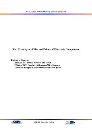
PHASE 2 KEY FINDINGS – COMPANY A CT scan of 30 cells and disassembly of 20 cells found only minor anomalies such as smallvoid/bubble or uneven stress. Samples show a similar pattern of deformation at upper corners. Upper right corner deformationappears to be deeper than upper left. Tear down analysis shows repeating deformation areas on separator at the corner locations.REPEATED DEFORMATION PATTERNS CAN BE OBSERVED AT THE CORNERS OF THE SEPARATOR5
ASSESSMENT – COMPANY AI.There may be multiple contributing factors relating to battery assembly/manufacturing anddesign that when combined led to the failure of the Note 7 in the fieldA. Battery assembly/manufacturing: Deformation at the upper cornersB.Battery design: Thinner separator could lead to poorer protection and reduced tolerance to manufacturing defects Higher energy density in general can exacerbate the severity of a battery failureII.One major failure mechanism is likely:A combination of deformation at the upper corners thin separator repeating mechanical stressesdue to cycling, causing higher possibility of separator damage leading to an ISC between aluminum andcopper foil at the cornerIII.Additional investigation is needed to understand the root-cause of the deformations at the uppercornersConfidential6
SCOPE OF PROJECT – COMPANY BPHASE 1All samples provided by SamsungFIELD EVENTSAMPLES ANALYSISTear-down examination of 10 damaged Note 7 devices with COMPANY B’sbatteries to understand the failure mechanism and potential causes of failurePHASE 2SYSTEM LEVELCOMPATIBILITY CHARACTERIZATIONTesting of 40 new Note 7 devices with COMPANY B’s batteries under variousconditions – to determine whether the device contributes to battery failurePHASE 3BATTERY SAFETY BOUNDARYCHARACTERIZATIONStudy battery failure mechanisms on 354 new COMPANY B batteries undervarious abuse conditions to identify potential battery safety issuesConfidential7
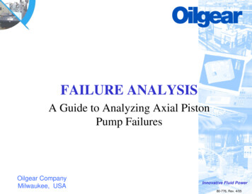
PHASE 1 KEY FINDINGS – COMPANY B Signs of internal short circuit (ISC) at different locationsof the cells from 5 of the damaged devices Signs of ISC at the tab locations of swollen cells Missing insulation tape on the cathode of swollen cells Sharp-edged protrusions on the tab welding spotsof swollen cellsCELLS WITH MISSING INSULATION TAPEA65: UNKNOWNNORMAL CELL WITHINSULATION TAPESSIGNS IONTAPE8
PHASE 2 KEY FINDINGS – COMPANY B Note 7 components do not increasethe battery cell temperature to a levelhigher than the specified threshold Note 7 maximum current drain meets the specificationsprovided by Samsung The maximum charging current, the maximum temperaturesand the maximum cell voltage are within the specificationswith the standard adapter provided by Samsung9
PHASE 3 KEY FINDINGS – COMPANY B The failure mode (ISC in winding edge) observed in field eventsamples can be reproduced by UL’s ISC or localized heat pad tests Flaws were readily found from 3D CT scan of some samples Tear-down analysis findings include: Uneven charge status on multiple samples Signs of internal short circuit Poor alignment and inconsistent shape anddimension of tabs and insulation tapes Sharp edge protrusion of welding joints10
ASSESSMENT (1/2) – COMPANY BI.No evidence of device-level compatibility issues that may have contributed to the failure ofthe Note 7 in the fieldII.There may be multiple contributing factors relating to production quality and battery designthat when combined led to the failure of the Note 7 in the fieldA. Production quality: B.Missing insulation tape on tab could result in higher possibility of ISCBigger protrusion of welding points in tab could lead to higher possibility of separator punctureMisalignment of insulation tape and/or tab could bring more risk of ISCBattery design: Thinner separator could lead to poorer protection and reduced toleranceto manufacturing defectsHigher energy density in general can exacerbate the severity of a battery failureConfidential11
ASSESSMENT (2/2) – COMPANY BIII.One major failure mechanism for field incidents is likely:The combination of (1) missing insulation tape (2) sharp edged protrusions on tab (3) thinseparator, all leading to a high possibility of an ISC between cathode tab and anode, subsequentlyresulting in heating and fireIV.Further analysis is needed to understand the root-cause of the damage to theedge/corner of the battery which results in ISC at that locationConfidential12
LEARN MORE ABOUT UL’SBATTERY EXPERTISE AT :UL.com/batteryscience13
SPEAKER BIOGRAPHYSajeev JesudasPresident, Consumer Business Unit, ULSajeev Jesudas leads UL’s focus on product quality, performance,security and safety for UL customers in the consumer, retail andfinancial payment services industries globally. He joined UL in2001 as President for Asia-Pacific operations and since then hasserved in many leadership positions with increasingresponsibilities, including the role of Chief Operating Officer andthat of President, International Operations. Jesudas is the currentChairman of the board of directors of the UL-CCIC joint venturecompany in China, and sits on the board of more than 20 ULaffiliate companies globally.Before joining UL, Jesudas worked in areas of sales and marketingand general management with a leading global manufacturer ofelectrical and electronic products for commercial, industrial, utility,and telecommunications markets, where he also held seniorpositions with Middle East and Asia Pacific regional responsibilities.Jesudas holds a Bachelor of Science degree in ElectricalEngineering from the University of Kerala, India, and an MBAdegree from the University of Texas, Austin.14
THIRD PARTY RIGOR. PROVEN SCIENCE.WORLD CLASS EXPERTISE.120YEARSOF EXPERTISEUL is a global independent safety sciencecompany with more than a century ofexpertise innovating safety solutions.Dedicated to promoting safe, sustainable andsecure living and working environments, ULMARKETS helps safeguard people, products and places,AROUND THE WORLDand builds trust in the the goods, solutions andinnovations of today and tomorrow.14315
OUR PEOPLE12,000 180 ASSOCIATESFACILITIESNorth America4,000 PeopleAfrica, Europe,Latin America,Middle EastAsia Pacific4,000 People2,000 People16
UL EMPOWERS TRUST THROUGH:INSPECTIONEDUCATION /TRAININGADVISORYSERVICESAUDITING /ANALYTICSTESTINGCERTIFICATIONSOFTWAREMARKETING CLAIMVERIFICATION1721
8 SIGNS OF SHORT CIRCUIT PHASE 1 KEY FINDINGS – COMPANY B Signs of internal short circuit (ISC) at different locations of the cells from 5 of the damaged devices Signs of ISC at the tab locations of swollen cells Missing insulation tape on the cathode of swollen cells Sharp-edged protrusions on the tab welding spots