Transcription
Rinnai RH180 Hybrid Tank –Tankless Water HeaterInstallation Fundamentals, Level II1
Rinnai Service and Support (800-621-9419) CRC – Consumer Response Center – general calls, consumer questions, etc.Available from 8 a.m. to 8 p.m. EST, Monday – Friday. Parts Department – parts orders.Available from 8 a.m. to 8 p.m. EST, Monday – Friday. Warranty Department – warranty claim issues.Available from 8 a.m. to 5 p.m. EST, Monday- Friday. Technical Support Department – technical issues related to the function and repair of allRinnai products.Available in the office from 8 a.m. to 8 p.m. EST, Monday – Friday AND 24/7/365 on call support fortechnicians who are at the service location. Technicians only, call 1-888-RINNAIS ( 888-746-6247) Engineering / Applications Department – calls related to product use and applicationsincluding sizing.Available from 8 a.m. to 5 p.m. EST, Monday - Friday.Rinnai America also provides the following websites for support: www.rinnai.us –for installation manuals, product specifications and supporting documents. More technical informationis available in the “For Professionals” section of the site under “Partner Portal”. Registration is required for access tothis portion of the website. www.trainingevents.rinnai.us – for registration in Rinnai product training classes and videos (live and online classes).Service and installation manuals and other technical documents are available under the “Resources” section of the site.
RH180 Hybrid Tank-Tankless Water HeaterLevel II Training ProgramInstallation Fundamentals3
RH180 TechnologyCombining Technologies:With the combination of a tank and a Rinnai tankless water heater intoone appliance, the RH180 hybrid provides increased hot water capacitywith the ease of a tank installation. 4
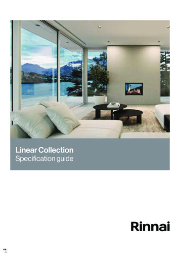
Product Component Identification ¾ hot water feedinto building 4” B-vent exhaustconnection Combustion air inletand filter Pressure relief valve ¾” cold water supplyinto tank 40 gallon storage tank 120 Volt power cord(not shown) Tankless water heaterengine Gas connection Temperature controller Hot water supply fromengine to tank Circulation pump fortank/engine Tank drain valve5 Cold water supplyfrom tank to engine
RH180Sequence of Operation6
Sequence of operation:1. When the water temperature at the bottom of the tank (at the tankthermistor) drops to a pre-determined temperature, the startupsequence will begin.8.2.2. The tankless engine’s combustion fan will begin turning, drawingfresh air from the space. This will allow the flammable vapor sensorto ensure the intake air is free of combustible vapors.4.3. The pump will begin circulating water through the tank-tanklessloop.5.4. The engine will fire when it detects the water flow from the pump.5. The heated water from the engine will be deposited back into thetank. The water will be directed toward the top of the tank close towhere hot water is being drawn into the plumbing system.3.6. Initially as water is drawn from the tank into the engine, the Delta Twill be fairly large and the engine will operate in a high fire mode.6.7.7. As the water at the bottom of the tank begins to heat, warmerwater will then begin to enter the engine — this will reduce theDelta T allowing a higher flow rate through the engine.1.8. As the water in the tank continues to warm and gets closer to theset temperature, the tankless engine will automatically reduce itsgas input.9.9. When the temperature at the bottom of the tank reaches the setpoint, the pump turns off — the tankless engine will go into astandby mode until the next start sequence.7
RH180Water HeaterSizing8
RH180 SizingWater HeatingOptionsMax input (Btuh/ Kwh)Tank Capacity(gal.)Showers In useat one timeElectric TankGas TankTime of availablehot water (min.)Time of availablehot water (min.)70⁰ temp rise70⁰ temp riseRecovery time(min.)70⁰ temp rise4.5 Kw4021108834,000 Btu401883640,000 Btu5026114075,000 Btu7550193291,300 Btu40Continuous1116Up to 199,000BtuN/AContinuousContinuousN/ARinnai RH180HybridTank -TanklessRinnai Tankless Data is based on a 50⁰F inlet water temperature and a 120⁰F hot water set point (70⁰F rise). Shower heads assumed to be 2.5 gpm mixed flow rate with 105⁰F at the fixture. Available hot water time and recovery time based on industry standard calculation methodsand Rinnai lab testing. Actual results may vary based on the application.
RH180Product Features &Safety devices10
Product Features 180 gallon First Hour Rating. Quick recovery: Approximately 16 minutes starting from a cold tank. Thermal Efficiency: 80%. Temperature controller: 5 temperature settings. Maintenance/diagnostic codes: Error codes displayed if a fault is detected. 40 gallon storage tank: Two inches of insulation, no heating element, burner, orvent stack which helps to minimize standby heat loss. Direct electronic ignition: No standing pilot. Blue-zircon-glass coated tank. Uses standard 4” B-Vent. Can be common vented with a furnace. Piping configuration and connections same as standard tanks. 1/2” gas line connection. Water is heated in the engine not the tank: Less thermal stress on the tank.11 Circulation system compatible.
Safety Devices Flame rod: Detects when flame is present or is extinguished. Overheat bi-metal sensor: Detects overheated water conditions. Boiling protection sensor: Monitors heat exchanger water temperature. Heat exchanger thermal fuse: Detects heat exchanger overheat condition. Burner/combustion fan sensor: Indicates if there is a blocked flue. Flammable vapor sensor: Monitors for flammable vapors in intake air supply. CO sensor: Monitors exhaust gasses for poor combustion, (NOTE: not a room COsensor). Built in surge protector. Power supply is protected by 5-amp glass fuse. Main circuit board monitors component operation and will post error codes ormaintenance codes on the temperature controller if abnormal operation is detected.12
SpecificationsModel13RH180Min / Max Gas Input RatesMin. 59,500 Btu-Natural Gas / 47,600 Btu-PropaneMax. 91,300 Btu-Natural Gas / 87,300 Btu-Propane(two stage burner, does not modulate between max-min inputs)First Hour Rating180 Gallons / hourStorage Tank Volume40 gallonsTemperature Selections110⁰F, 120⁰F, 130⁰F, 135⁰F, 140⁰F (43⁰C, 49⁰C, 54⁰C, 57⁰C, 60⁰C )Weight150 lbs. (68kg)Thermal Efficiency80%Noise Level50 dBElectrical120 VAC, 60 Hz. , Normal Operation - 150 watts / Standby – 3 watts (5 ampfuse)Minimum Gas Supply Pressure4.0” w.c. Natural Gas / 8.0” w.c. PropaneMaximum Gas Supply Pressure10.5” w.c. Natural Gas / 13.5” w.c. PropaneConnectionsGas Supply: ½” MNPT – Water Connections: ¾” MNPTWater Supply Pressure20 - 150 psi (Recommend 30 – 50 psi for maximum performance)Sensor and SwitchesFlammable Vapor, Combustion Air CO Sensor, Bi-Metal Overheat SwitchSee Operation / Installation manual for more complete information. Specifications subject to change without prior notice.
RH180InstallationRequirementsA licensed professional must install the appliance, inspect it and leak test it before use. Thewarranty may be voided due to improper installation.The installer should have skills such as: Gas sizing Connecting gas lines, water lines, valves and electricity. Knowledge of applicable national, state and local codes. Installing venting through a wall or roof. Venting Category I, Fan Assist Appliances per NFPA 54 and local codes.14 If you lack these skills contact a licensed professional.
Installation Location Not approved for mobile homes or outdoor installations (can be used in light commercialapplications where the temperature requirement do not exceed 140⁰ F). Installation must be accomplished in such a manner that if the tank or any connectionshould leak, the flow of water will not cause damage to the structure. For this reason it isnot advisable to install the water heater in an attic or upper floor. When such locationcannot be avoided, an approved drain pan should be used and piped to a drain line oroutside the home. Use an approved tank water heater drain pan. (Rinnai recommends 26” diameter pan. Seenext page for example). See International plumbing code for details. Gasoline or other flammable substances MUST NOT be stored in the vicinity of the waterheater. A stand is not required as this water heater complies with the FVIR requirements and theburner and igniter are positioned greater than 18 inches from the base of the unit (verifywith local codes). If installed in a crawl space with a dirt floor, position the unit on a solid level surface (suchas concrete) away from the ground’s moisture. If installed in a closet or alcove, ensure all intake (combustion) air requirements arefollowed, see owner’s/installation manual. The RH180 meets or exceeds the National Appliance Energy Conservation Act Standardswith respect to insulation and standby losses. If an insulation blanket is still desired, followthe installation procedures outlined in the Operation and Installation manual.15
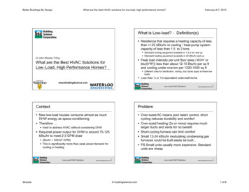
Drain Pan Installation.Rinnai recommends using a 26” diameter drainpain minimum to provide protection from leaksand still allow removal of the front pipe/pumpshroud for service.Use only an approved drain pan and install inaccordance with all applicable plumbing andbuilding codes.
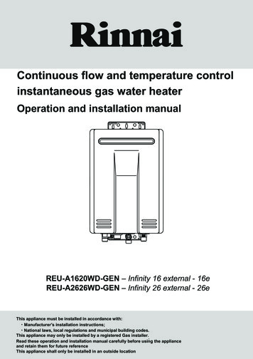
Installation LocationMinimum Clearances:The minimum clearances fromboth combustibles and noncombustibles construction is: 0 inches from the sides.0 inches from the back.12 inches from the top.4 inches from the front.NOTE: These clearances areminimums. Be sure to allowsufficient clearance for futureservicing and maintenance.17
Dimensions18
Electrical and Water InstallationCode Adherence- Installation MUST comply with National, State, and Local codes.Electrical Requirements-Standard three-prong 120 VAC, 60 Hz. grounded circuit.-Ensure plumbing lines are grounded in accordance to Local, State, and National codes.Water Installation Requirements- Supply pressure 20 – 150 psi.-A temperature/pressure relief valve is supplied with the product. The discharge must bepiped per local code requirements.-Water quality should meet Part 143 of the National Secondary Drinking Water Regulations.(see installation manual for guidelines).-Ensure inlet water filter on appliance is clean before filling tank.-Do not operate water heater unless tank is completely full of water.19
Electrical and Water InstallationWater Requirements (continued)-Make sure the water heater and its water lines are protected from freezing. Damage dueto freezing is not covered by the warranty.-Do not use this appliance in an application such as a pool or spa heater that useschemically treated water. (the RH180 is suitable for filling large or whirlpool spa tubs usingpotable water).-If a water heater is installed in a closed water supply system, such as one having abackflow preventer, a means shall be provided to control thermal expansion (expansiontank).-If required, install a vacuum relief valve per local codes. (Massachusetts 248 CMR section10.14 (I) “All potable water pressure tanks shall be provided with a vacuum relief valve atthe top of the tank that will operate up t a maximum water pressure of 200 P.S.I.G. and toa maximum water temperature of 200 F.”)
RH180VentingandAltitude Requirements! WARNINGImproper installation of the vent system and its components, or failure to follow all installation instructions,can result in property damage or serious injury21
Vent Guidelines: Combustion airCombustion air is drawn from the room in which the water heater is installed. This water heaterrequires adequate combustion air for ventilation and dilution of flue gasses. Failure to provideadequate combustion air can result in unit failure, fire, explosion, serious bodily injury or death.Read all the venting guidelines in the Operation and Installation manual.Note: Combustion air must be free of corrosive chemicals. Donot provide combustion air from corrosive environments.Appliance failure due to corrosive air is not covered by thewarranty. Combustion air must be free of acid forming chemicals suchas sulfur, fluorine and chlorine. These chemicals have beenfound to cause rapid damage/decay and could become toxicwhen drawn into the combustion chamber of the appliance. Such chemicals can be found in, but not limited to bleach,ammonia, cat litter, aerosol sprays, cleaning solvents,varnish, paint, and air fresheners. Do not store any of the products listed above in the vicinity ofthis water heater.The room in which the water heater is installed must be definedas a confined or unconfined space based on the coderequirements pertaining to Category 1 type appliances.22Air from thespace is usedforcombustion
Vent Guidelines: Combustion airUnconfined space:An unconfined space is defined in NFPA 54 as “a space whose volume is not lessthan 50 cubic feet per 1,000 Btu/hr. (4.8 m3 per kW per hour) of the aggregate inputrating of all appliances in that space. Rooms communicating directly with the spacein which the appliances are installed, through openings not furnished with doors, areconsidered a part of the unconfined space”. If the “unconfined space” containing theappliance(s) is in a building with tight construction, additional outside air may berequired for proper operation. Outside air openings should be sized the same as fora confined space.Confined space:(Small room, Closet, Alcove, Utility Room, Etc.)A confined space is defined in the NFPA 54 as “a space whose volume is less than50 cubic feet per 1000 Btu/hr. (4.8 m3 per kW per hour) of the aggregate input ratingof all appliances installed in that space”.
Vent Guidelines: Combustion airConfined and Unconfined space examples:25 x 25 x 8 5000 cubic feet5000 cubic feet ൊ 50 100100 x 1000 100,000 BtuUnconfined space with a 91,300 Btu waterheater.2425 x 25 x 8 5000 cubic feet5000 cubic feet ൊ 50 100100 x 1000 100,000 BtuConfined space with 91,300 Btu waterheater and a 100,000 btu furnace. Total 191,300 Btu.
Vent Guidelines: Combustion airA confined space must have two combustion air openings. Size the combustion airopenings based on the Btu input for all gas utilizing equipment in the space and themethod by which combustion air is supplied.Louvers and Grills:When sizing the permanent opening:Consideration must be taken for the design of the louvers or grills to maintain the required free arearequired for all gas utilizing equipment in the space. If the free area of the louver or grill is notavailable, assume wood louvers will have 25% free area and metal louvers / grills will have 75%free area. Under no circumstance should the louver, grill or screen have openings smaller than ¼”.Example:Wood: 10 inches x 12 inches x 0.25 30 square inches of free space.Metal: 10 inches x 12 inches x 0.75 90 square inches of free space.Combustion air provided to the appliance should not be taken from an area of the structure thatmay produce a negative pressure (i.e. exhaust fans, powered ventilation fans).25
Vent Guidelines: Combustion airUsing Indoor Air For Combustion:When using air from other room(s) in the building, the total volume of the room(s) must be ofadequate volume (Greater than 50 cubic feet per 1,000 Btu/hr.). Each combustion air openingmust have at least one square inch of free area for each 1,000 Btu/hr, but not less than 100 squareinches each.26
Vent Guidelines: Combustion airUsing Outdoor Air For Combustion:Outdoor air can be provided to a confined space through two permanent openings, onecommencing within 12 inch (300 mm) of the top and one commencing within 12 inches (300 mm)of the bottom, of the confined space. The openings shall communicate to the outside by one of twoways.27
Vent Guidelines: Combustion airWhen communicating directly with outdoors throughhorizontal ducts, each opening shall have a minimum freearea of 1 square inch per 2000 Btu/hr (1100 mm2 /kW) oftotal input rating of all appliances in the confined space.Note: If ducts are used, the cross sectional area of the ductmust be greater than or equal to the required free area of theopenings to which they are connected.When communicating indirectly with the outdoors throughvertical ducts, each opening shall have a minimum free areaof 1 square inch/4,000 Btu/hr (550 mm2 /kW) of total inputrating of all appliances in the confined space.Combustion air to the appliance can be provided from a wellventilated attic or crawl space.Note: Check your local building codes toensure providing makeup air in themanner you choose is allowed.28
Vent Guidelines: Exhaust This water heater must be vented/terminated vertically to the outside of the building orstructure. This water heater is NOT designed or certified for side wall horizontal ventterminations. All installations must be vented in accordance with the National Fuel Gas Code NFPA 54/ANSIZ223.1 – latest edition and the requirements of State or local codes. In Canada, the furnacesmust be vented in accordance with National Standard of Canada, CAN/CSA B149.2 – latesteditions and amendments and the codes of the local utility or other authority havingjurisdiction. NOTE: The vertical height of the Category I venting system must be at least as great as thehorizontal length of the venting system. All vent (Category I) passing through a concealed space, an attic or floor, MUST be Type Bdouble wall vent and/or Type B double wall vent connectors. For vent passing through aninternal wall, use Type B with ventilated thimble ONLY. The RH180 CANNOT be vented into any chimney serving an open fireplace or any other solidfuel burning appliance. Use the same diameter Category I connector or vent as permitted by NFPA 54/ANSI z223.1venting tables.29
Vent Guidelines: Exhaust It is not permitted to reduce vent diameter (4”). Vent or vent connector runs should be as short anddirect as possible. Vertical outdoor runs of Type B or ANY single wall ventbelow the roof line are NOT permitted. All horizontal vent runs to be sloped up away from theRH180 a minimum of ¼” (6mm) per foot. All horizontal vent runs are to be supported, at aminimum, every 6 ft. (2 m) using suitable clamps and/or metal straps. Existing exhaust vent or chimney is to be checked to ensure they meet clearances and localcodes. The RH180 can ONLY be connected to a manufactured chimney or vent that complies with arecognized standard. Venting into a masonry or concrete chimney is only permitted as outlined inthe NFPA54/ANSI Z223.1 National Fuel Gas Code venting tables. It is therefore a contractualobligation on the part of the installer to follow all safe venting requirements.30
Vent Guidelines: ExhaustVent Dampers:Vent dampers must be certified in accordance with ANSI Z21.68.Before installing any flue damper, consult the local gas authority and damper manufacturer for properinstallation.Thermal Operated Vent Dampers: Should NOT be used with this appliance. This appliance has athermal efficiency greater than 80%. This higher efficiency will result in lower flue gas temperatures.Such temperatures may be too low to activate a thermal operated vent damper. Use of a thermaloperated flue damper on this product may result in spillage of exhaust gases and ultimately carbonmonoxide poisoning.Vent Inspection:The entire vent system (Combustion air ducts, louvers, and exhaust vent) must be checkedperiodically for signs of obstruction or damage. If damaged components are observed they must berepaired or replaced immediately.Vent Size:This water heater is equipped with a 4” vent adaptor and must never be attached to a vent smallerthan 4”. Certain applications may require vent diameters greater than 4”. Consult your local gassupplier or authority to aid in the proper vent diameter selection per the requirement of the vent tablesin the current edition of the National Fuel Gas Code ANSI Z223.1/NFPA 54.31
High Altitude InstallationsSet dip switch 3 to the position shown in table below for your altitude. The default setting for theappliance is 0 – 2,000 ft. (0 - 610 meters) with dip switch 3 in the OFF position. The maximumallowed altitude for this appliance is 5,400 ft. (1,646 meters).0 – 2000 ft.(0- 610 m)2001 – 5400 ft.(610 – 1646 m)Dip switch 3 inthe bank of 8switches willadjust the unitfor altitudes of2001- 5400 feetWARNING: Do not adjust the other dip switches unless specifically instructed to do so.32
RH180Gas Supply InstallationWhen sizing a gas system you MUST take into account the type pipe and gas being used, theinlet gas pressure being fed to the site, meter, regulator and/or tank size and Btu ratings.Improperly sized gas system will result in poor performance of all gas appliances.33
Gas InstallationThe RH180 has a maximum input of 91,300 Btu. Under most circumstances the same supply gasline that supplies a standard atmospheric tank water heater (40 gallons or more) will adequatelysupply the RH180. Consider the following: All gas appliances in the structure MUST be included in gas sizing calculation. Flexible gas supply lines connected directly to the RH180 MUST be able to supply a minimumof 91,300 Btu for NG or 87,300 Btu for LP. Consult the NFPA 54 National Fuel Gas Code Pipe Sizing Guidelines to ensure adequate gassupply is provided. Supplied gas pressure must be within the recommendations listed on the unit’s rating plate. The RH180 requires a higher gas supply than standard 40 gallon tank water heaters.-The RH180 has a maximum input rating of 91,300 Btu (natural gas models).-The average 40 gallon gas-fired tank water heater has an input rating of approximately 40,000 Btu.-In this example, the difference between the RH180 and the 40 gallon tank water heater is 51,300 Btu.This additional gas load must be considered when installing this product. Issues caused by insufficient gas supply:- Poor appliance operation or intermittent error codes.- Rumbling noises due to insufficient air/gas mixture.If any symptom exists suggesting a gas supply issue may be present, a gas manometer will be needed toverify incoming pressure.
Gas Supply Sizing ProcedureThis gas supply sizing procedure is known as the longest length method. This example is for Natural gas. A fullexplanation of NG and LPG pipe sizing can be found in the National Fuel Gas Code Manual1. Using this method you firstdetermine the total pipe length fromthe gas meter to the appliance farthestfrom the meter. (60 ft. in this example)Outlet CRH18091,300 Btu/hrOutlet Dfurnace100,000 Btu/hr10 ft.20 ft.Point of Delivery(gas meter)35Pipe Size (in.)Nominal:½15 ft.10 ft.10 ft.Outlet Brange/oven75,000 Btu/hr¾11¼1½Capacity in Cubic Feet of Gas per Hour(CFH Btu/1000)Length(ft)2. Once this length is determined findthe line on the appropriate table in theNFPA 54 manual that corresponds tothat length (for your pipe, type of gas,inlet pressure and specific gravity).3. The 60 ft. measurement will be theonly length used for this calculation.Schedule 40 Metallic Pipe, Natural Gas, less than 2 psi inletpressure, 0.5” w.c. pressure drop, 0.60 specific 7257528791706012623748672815 ft.5 ft.Outlet Agas fireplace30,000 Btu/hr
Gas Supply Sizing ProcedureUsing the row for 60 ft on thistable, you can now determinepipe sizes.1. Outlet A, section 1, can draw upto 30,000 Btu. This sectionrequires ½” pipe minimum.2. Outlet B, Section 2, can drawup to 75,000 Btu. This sectionrequires ¾” pipe minimum.3. Outlets C and D, section 3,share a common supply pipewhich can draw up to a total of191,300 Btu. This section4.requires 1” pipe minimum.5.10 ft.20 ft.Schedule 40 Metallic Pipe, Natural Gas, less than 2 psi inletpressure, 0.5” w.c. pressure drop, 0.60 specific gravity.Outlet Dfurnace100,000 Btu/hrOutlet CRH18091,300 Btu/hr36Nominal:3.15 ft.10 ft.½¾11¼6513725752815 ft.Outlet Brange/oven75,000 Btu/hr7914. Section 4 is supplying outlets A, C and D.These outlets can draw up to 221,300 Btu.This section requires 1” pipe minimum.5. Section 5 is supplying all appliances. Thetotal Btu load for the home is 296,300 Btu.This section requires 1 ¼” pipe minimum.1.10 ft.1½Capacity in Cubic Feet of Gas per Hour(CFH Btu/1000)Length(ft)602.Point of Delivery(gas meter)Pipe Size (in.)5 ft.Outlet Agas fireplace30,000 Btu/hr
Gas System – Two stage piping exampleIf resizing gas supply lines is not a feasible option, a two stage supply system may be used depending onlocal code guidelines. Two stage systems operate in the following manner: Higher pressure (usually 2 lbs or approximately56” w.c.) is supplied for a large portion of thesupply system. By increasing the system pressure, thisovercomes volume inadequacies. NOTE: Neverapply high pressure (such as 2 lbs) to ahousehold appliance unless stated by themanufacturer. All Rinnai tankless water heatersrequire no more than ½” lb inlet pressure (14”w.c.).The below example has the following parametersGas: NGInlet pressure: 2 PSIOutlet CRH18091,300 Btu/hrOutlet Dfurnace100,000 Btu/hrMain gas metersupplies 2 lbs ofpressure throughexisting pipesRegulators are placed inclose vicinity to all appliancesbringing pressure to appliancestandard (1/4-1/2 lb) Regulators are placed close to each appliance toreduce pressure to the appliance standard of ½lb or approximately 7-14” w.c. Follow NFPA 54 guideline and all coderequirements when sizing two stage systems. Two stage systems can be used in NG or LPapplications—sizing values differ by gas type Gas meter capacity must also be considered37Point of Delivery(gas meter)Outlet Brange/oven75,000 Btu/hrOutlet Agas fireplace30,000 Btu/hr
RH180TemperatureController38
Temperature Controller39
Temperature ControllerFive temperature settings are available. Push the up and down arrows toselect the desired temperature setting. The number on the displaycorresponds to the temperature scale below.1.2.3.4.5. 110 F 120 F 130 F 135 F 140 FTo display the recovery flow rate (in gallons per minute) through the unit (notthe fixture), press and hold the UP button. After 3 seconds also press theON/OFF button then release both buttons.To display the temperature supplied to the storage tank in degreesFahrenheit, press and hold the DOWN button. After 3 seconds also press theON/OFF button then release both buttons.(Note: the temperature display will be one or two digits, Example: 14 140 to 149.40
RH180MaintenanceandWarranty41
Maintenance – Inlet Water Filter Rinnai recommends that the inletwater filter be cleaned before theinitial operation of a new unit. Before removing the inlet filter,ensure that the water supply hasbeen turned off. If the tank is already full, it must bedrained from the drain valve at thebottom of the tank. See filter location in picture at right. Remove any debris from the filtereither by rinsing or low pressurecompressed air. When reinstalling the filter assembly,it should be hand tightened only.42
Maintenance – Intake air filter The RH180 is a fan assistedwater heater. Intake air isdrawn into the appliance fromthe surrounding area. To maintain optimumperformance, periodically cleanthe air filter. Do not operate unitif the filter is not in place. A dirty air filter could result incodes 05, 10 or 13 beingposted on the temperaturecontrol panel. See manual fordetails.43
Maintenance - Tank Drain the water from the tank at least once per year. This will remove excesssediment from the bottom of the tank. Accumulated sediment will reduce theefficiency and life expectancy of the tank. Manually operate the relief valve at least once per year. The water heater is equipped with an anode rod that is designed to prolong thelife of the glass-lined tank. This anode is slowly consumed protecting the tankfrom corrosion. The anode should be checked every two years. If more thanhalf of the anode has been consumed it should be replaced. In certain conditions, the anode rod can react with the water producingdiscolored water or an odor. This can be a result of the reaction between theanode and hydrogen sulfide gas dissolved in the water. For more informationsee the “required maintenance” section of the operation and installation manualunder “Anode”.44
Maintenance – Engine Heat Exchanger Flushing the heat exchanger consists ofpumping virgin food grade whitevinegar or food grade citric acid throughthe copper heat exchanger to removelime scale or calcium buildup. Damage caused by lime or scalebuildup is not covered under the waterheater’s warranty. Specific flushing instructions can befound in the System Maintenancesection of the operation and installationmanual.5 gallon bucket to be filledwith 4 gallons of food gradewhite vinegar or citric acid.45
Internal view of tank¾” cold feed inside tank¾” anode rod inside tank¾” circulation pump feed lineback into tankBottom pan of tank46
Piping – Typical InstallationTypical Installations.AHot Water Outlet*ICombustion Air ScreenBHot water Outlet Valve*JCTemperature – PressureRelief valveOperation Unit /Temperature ControlKOutlet Receptacle*Drain Pan*DCold and Hot Unions*LECold Water Supply valve**FCold Water Supply*GThermal Expansion Tank*M Temperature – PressureRelief Valve DischargePipe (do not cap plug orreduce)H4” B-Vent*NDrip Leg (Sediment Trap)*OGas Union*PGas control valveQThermostatic Mixing Valve*RNon-Tempered ReturnLine*SNon-Tempered SupplyLine*Mixing Valve Installation* Field Supplied47
Installation Method (2 units)Pictures are for illustration Purposes only.Parallel Piping (recommended method)Hot water outCold water inSeries Piping (not allowed)48Drip pans MUST be installed under each water heaterper local or State code,
Component Description49
Component Description50
Maintenance CodesMaintenance codes flash on the temperature controller when a fault occurs.Depending on the code, water flow or power may need to be reset to clear the code.S
(Massachusetts 248 CMR section 10.14 (I) "All potable water pressure tanks shall be provided with a vacuum relief valve at the top of the tank that will operate up t a maximum water pressure of 200 P.S.I.G. and to a maximum water temperature of 200 F.") Electrical and Water Installation