Transcription
PFMEAProcess Failure Mode and EffectsAnalysisJames Davis, General Dynamics
PurposeThe purpose of this presentation is toshare the benefits of a detailed ProcessFlow Diagram, conducted during aProcess Failure Mode and EffectsAnalysis, that will ensure productquality in the manufacturing/assemblyprocess.James Davis, GDLSSlide Number: 2
IntroductionJames Davis, GDLSSlide Number: 3
Definition of FMEAA FMEA is an analytical tool that uses adisciplined technique to identify and helpeliminate product and process potentialfailure modes.ooooBy ID of potential failuresAssessing the risks caused by failure modes andIdentify corrective actionsPrioritizing corrective actionsCarry out corrective actionsJames Davis, GDLSSlide Number: 4
Most COMMON Types of FMEA'sDesign (Potential) Failure Modes andEffects Analysis-DFMEA Focus is on potential design- related failuresand their causes.Process (Potential) Failures Modes andEffects Analysis-PFMEA Focuses is on potential process failures andtheir causes.James Davis, GDLSSlide Number: 5
Value of FMEA'sz Aidsin improving designs for products andprocess Increased safety Enhances Customer SatisfactionooBetter QualityHigher Reliabilityz Contributesto cost savings Decreases warranty costs Decreases waste, non-value added operationsJames Davis, GDLSSlide Number: 6
PFMEA'sz Focusis on potential process –relatedfailures and their causes. Main drive is to understand the process through theidentification of as many potential failures as possible.oe.g. Incorrect material usedz PFMEAtypically assumes that the designis sound.z Development of Recommended Actions istargeted at eliminating the Root Cause ofthe potential failures.James Davis, GDLSSlide Number: 7
PFMEAThree Parts:zProcess Flow Diagram (PFD)zProcess Failure Mode and EffectsAnalysis (PFMEA)zProcess Control Plan (PCP)James Davis, GDLSSlide Number: 8
Information FlowCustomer Requirements:SOR, Vehicle Tech Specs,System Technical SpecsProduct Definition:Key Product Characteristics, DFMEAProcess Definition:Process Flow Diagram (PFD),Product and Process CharacteristicsFailure Mode Analysis:PFMEAControl Strategy:Control Plan,Error proofingManufacturing:Work Instructions & Process MonitoringJames Davis, GDLSSlide Number: 9
DFMEA/PFMEA InformationInterrelationshipsProcess FlowDiagramBoundary (Block)Diagram, P- Diagram,Etc.DFMEADesign FMEADesign VerificationPlan & Report(DVP&R)James Davis, GDLSPFMEAProcess FMEAProcess ControlPlanSlide Number: 10
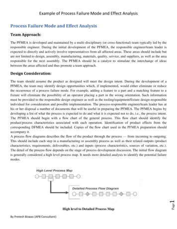
Process Flow DiagramszThe Process FlowDiagram provides alogical (visual)depiction of theprocess that is beinganalyzed.James Davis, GDLSSlide Number: 11
Process Function / Requirementz TheSAE/AIAG PFMEA guidelines describe twomethods of defining process functions.Either or both may be used.z Process Functions may be described in terms of: The product features/characteristics that arecreatedor The process actions that are performedz Process functions should be identified in detailas necessary to provide information for thePFMEA to develop effective Process ControlsJames Davis, GDLSSlide Number: 1212
Process Function / Requirementz Considera simple operation to drill a hole in ametal partz The product characteristics & requirements are: Hole size: 4.00 mm /- 0.13YX4.00 Hole Location:X 28.0 mm /- 0.2Y 15.0 mm /- 0.2 Perpendicular to surface, no burrs, etc.z Theprocess operation must create theseproduct characteristics and meet therequirementsJames Davis, GDLSSlide Number: 1313
Process Function / Requirementz Todrill the correct hole size in thespecified location, the process must: Position and hold the part Align the part fixturingwith the drill position Assure the correct drillbit size is used Set and control drill speed Anticipate tool wear andschedule preventive maintenancez Ifthe Function/Requirement is defined inthe PFMEA as “Drill Hole” could any ofthese be missed?James Davis, GDLSSlide Number: 14
Process Flow Diagram (PFD)zProcess Flow Diagram is the foundation The process must be defined step by step, includinginterfaces The PFD provides the structure to document what productcharacteristics and requirements (OUTPUTS) are affectedby a given operation and how these characteristics andsources of variation are controlled (INPUTS) PFD is a graphical representation of every possible path apart can take through the anticipated manufacturingprocess A well defined PFD establishes the foundation for thePFMEAzHelps in developing equipment specifications. How will the process control non-conforming material? How and when will inspections be performed, what isrequired? How and when will parts be re-introduced into theprocess?James Davis, GDLSSlide Number: 15
Process Flow Diagram (PFD)zHidden Factories: Interfacing ProcessesQuality AuditsRework ProcessesAlternative ProcessesScrapPart BuffersPart MovementProduct/tooling ChangeoversPart Ident./LabelingTeardownGauging StationsReject Handling Interface process issues affect quality performanceoozRework and scrap parts bypass process controlsMixed parts in the manufacturing process at changeoversNeed for common systems Part of the overall Quality Strategy must includeoCommon content, common format, common approach Quality strategy must extend to suppliersoConsidered an extension of the Total Quality processesJames Davis, GDLSSlide Number: 16
SAE J1739James Davis, GDLSMarch 2009Slide Number: 17
Micro Level PFD ExampleJames Davis, GDLSSlide Number: 18
Process CharacteristicsJames Davis, GDLSSlide Number: 19
PFD Feeds PFMEAIdentify the Function(s)zFunction is a description of what theProcess does to meet the requirements¾Related to process specification and productcharacteristics¾Comes from the PFD operation description columnzFunctions can be described as:¾ Do this operation ¾ To this part or material ¾ With this tooling or equipment James Davis, GDLSSlide Number: 20
PFD Feeds PFMEAJames Davis, GDLSSlide Number: 21
Linkage to PFMEAJames Davis, GDLSSlide Number: 22
PFMEA Example continued.James Davis, GDLSSlide Number: 23
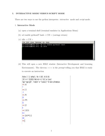
Sources and Types of Manufacturing VariationSource of VariationTypes of VariationTypical Process ControlsOperator Skill,Ergonomic FactorsTraining, instructions, visual aids, feedbacklayout, motion analysis, human factorsComponent /MaterialIncoming raw material, purchasedparts, previous operationsSupplier management, internal controls, errorproofingEquipment /MachineMachine capability, adjustment,wear over timeEquipment specifications, closed-loopmachine controls, preventive maintenanceTemperature, humidity, dust, noiseClimate control, air filtration, clean room,sound insulationOperatorEnvironmentSequence, procedure, layoutIndustrial Engineering techniques,Lean Flow analysisSet Up(for stableprocesses)Initial set up or adjustmentProcess specification, first / last piece check,automated controlsToolWear over time, breakage,tool-to-tool differencesPredictive maintenance, detection errorproofing, tooling specificationsRepair, replacement, reassembly,adjustmentInstructions, error-proofing, machinequalification, production trial runPosition tolerance, adjustment,wear over timePredictive maintenance, prevention anddetection error-proofingMethods & SystemsMaintenanceFixture / PalletJames Davis, GDLSSlide Number: 24
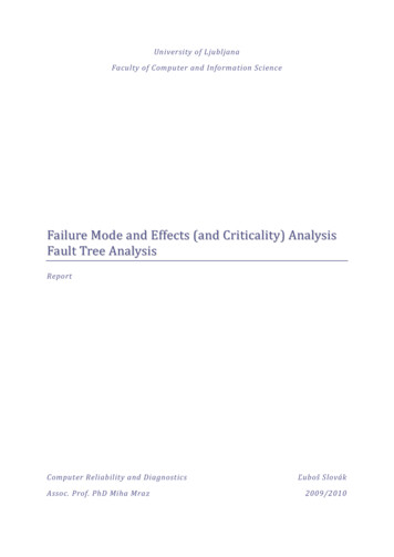
Process Control PlanzPCP will be based on the previousactivities in PFD and PFMEA.zReview the PFMEA informationdeveloped & supplied and use to identify: Specific controls that may be needed due to theinformation added Identify which controls are Product or ProcessoNote any Special CharacteristicsoIdentify evaluation methods, frequency and ControlMethodsoNote Reaction Plans (particularly related to NC parts)James Davis, GDLSSlide Number: 25
Process Control Plan ExampleForm 818-1 (Rev 12Apr02)CONTROL PLANPrototypePre-LaunchProductionPart Number/Latest Change LevelKey Contact/PhoneCustomer Part NumberPart Name/DescriptionSupplier/PlantSupplier CodeCoreTeamSupplier/Plant Approval/DateCustomer Engineering Approval/Date (If Req'd.)Other Approval/Date (If Req'd.)Other Approval/Date (If Req'd.)CharacteristicsPart/Process Name /ProcessOperation DescriptionNumber300Initiate weld sequence/Machine,Device, Jig,Tools for Mfg. No.Robotic Armcontroller.TIG welders.Perform TIG weld offrame parts.James Davis, GDLSControl Plan No:Date (Orig.)Date (Rev.)ProductProcessCustomer Quality Approval/Date (If Req'd.)MethodsSpecialSampleChar. Product / Process EvaluationSpecification / MeasurementClass.Size FrequencyToleranceTechniqueWeld beadsper designspecification.Tube welds meetpull test withfailure in parentmaterial.Pull testusing testfixture 20-1.yesWeld appearancemeets visualstandard.Weld voltageyes24 Volts AC /- 2.0 voltsOperator100% Eachevaluation topiece.Visual StdTB20-VS1Machine100% Each weld Closed-loop machineControlcycle.control.Weld voltageyes24 Volts AC /- 2.0 voltsVisualOnceeachInert gas flowrateyes5 cubic feet / min. /- 0.5 cfmVisualtwiceInert gas flowrateyes5 cubic feet / min. /- 0.5 cfmVisual ofOnceverification eachof FlowMeterGood welds,no visibledefects.1 pc.Per shift.Control MethodReactionPlanHydraulic pull testinstruction TI21-01Process monitoringform PMF-20-01Quarantinematerialsince lastgood pulltest.Visual inspection OWI Remove part#20-01.and send torepair.Scrap part &Re-startwelder.Shift start Set-up OWI #20-02 & ScrapForm PMF-20-02current part.orShut down.change- Periodicover ormaintenance per PM- Notifymaintenancemaint.WI #20.event.Per shift. Operator cleans gas Notifymaintenancecup twice per shift.PM-WI-20. Processmonitoring form PMF20-01Shift startorchangeover ormaint.eventSet-up OWI #20-02 &Form PMF-20-02.EquipmentCalibration Procedure#368Quarantinematerialsince lastgood pulltest.Notifymaintenance.Slide Number: 26
Process Control Plan ExampleCharacteristicsPart/ProcessNumberProcess Name /Operation DescriptionMachine,Device, Jig,Tools for Mfg. No.ProductProcessMethodsSpecialChar.Class.Product / ProcessSpecification Frequency1 pc.Per shift.Control MethodReactionPlan.Initiate weld sequence / Robotic ArmClose and latch curtain TIG welders300300.Initiate weld sequence / Robotic ArmPerform TIG weld ofTIG weldersframe parts.and controllers.Weld beads perdesignspecification.Tube welds meetpull test with failurein parent material.Pull testusing testfixture 20-1.yesWeld appearancemeets visualstandard.Operator100%evaluation toVisual StdTB20-VS1.Eachpiece.Weld voltageyes24 Volts AC /- 2.0 voltsMachineControl100%Each weld Closed-loop machinecycle.control.Weld voltageyes24 Volts AC /- 2.0 voltsVisualOnceeachShift startor changeover ormaint.eventInert gas flowrateyes5 cubic feet / min. /- 0.5 cfmVisualtwicePer shift.Good welds, novisible defects.Initiate weld sequence /Confirm Weld voltageInitiate weld sequence /Confirm Inert Gas flowrateInitiate weld sequence /Confirm Wire feed rateJames Davis, GDLSHydraulic pull testinstruction TI41-01Process monitoringform PM-20-010Quarantinematerialsince lastgood pulltest.Visual inspection OWI Remove#20-010.part andsend torepair.Set-up OWI #20-02 &Form PM-20-02Periodic maintenanceper PM-WI #20.Operator cleans gascup twice per shiftPM-WI-2500. Processmonitoring form PMF20-10Shift start Set-up OWI #20-02 &or change- Form PM-00-02.Equipment Calibrationover orProcedure #368maint.eventInert gas flowrateyes5 cubic feet / min. /- 0.5 cfmVisualOnceverification of eachFlow MeterWeld wirefeed rateyes300 mm / minute /- 10 mm / min.MachineControl100%Each weld Closed-loop machinecontrol.cycle.Weld wirefeed rateyes 300 mm / minute /- 10 mm / min.Operatorsetup checkandverification100%Shift start Set-up OWI #20-020 &or change- Form PM-20-020over orPredictivemaint.maintenanceeventpinch roller replace @180 days.Scrap part& Re-startwelderScrapcurrentpart.Shut ematerialsince lastgood pulltest.NotifyScrap part &maintenanRe-startce.welderScrap currentpart.Shut down.Notifymaintenance.Slide Number: 27
Case Studies – Supplier AzzzNot ISO Certified, Primarily Defense business baseSole Source - Unique TechnologyNo Process Flow Operator work instruction for 100 piece componentooz20 process steps on a single piece of paper (included machining)Building the component relied on Tribal KnowledgeDiagramming the Process Flow 20 steps turned into 951 steps to produce the component 22 manufacturing related issues (from DFMEA) wereincorporated in the PFD/PFMEAzSupplier A used PFD - FMEA to Develop work instructions Determine the requirement to developed training programsfor assemblers / machinists, QC personnel Develop safety program / trainingJames Davis, GDLSSlide Number: 28
Case Studies – Supplier BzzzISO Certified, Primarily Defense business baseSole Source - Unique Design“Fair” Documented Process Flow Relied on a combination of operator knowing what shouldbe done next with operator work instructions.ozHowever it did allow for repeatable assembly of component withskilled employeeDiagramming the Process Flow 270 step PFD became 1,170 stepsozFMEA analysis determined: work instructions that neededimprovement and new work instructions were requiredSupplier B used PFD- FMEA to Update work instructions to error proof build processJames Davis, GDLSSlide Number: 29
Case Studies – Supplier CzzISO Certified, Defense/Civil business baseWell Documented Process Flow Operator work instructions allowed for repeatable assembly Error Proofing allows for assembly with “average”employeeszDiagramming the Process Flow 263 step PFD became 268 steps 32 manufacturing related issues (from DFMEA) wereincorporated in the PFD/PFMEAozFMEA analysis determined: work instructions that neededimprovement and new work instructions were requiredSupplier C used PFD- FMEA to Update work instructionsJames Davis, GDLSSlide Number: 30
Case Studies – Supplier DzzISO Certified, Aerospace business baseVery Small Company 2 Mas
SAE J1739 March 2009. James Davis, GDLS Slide Number: 18 Micro Level PFD Example. James Davis, GDLS Slide Number: 19 Process Characteristics. James Davis, GDLS Slide Number: 20 PFD Feeds PFMEA Identify the Function(s) zFunction is a description of what the Process does to meet the requirements ¾Related to process specification and product characteristics ¾Comes from the PFD