Transcription
TFEC 4-2020Design Guide forTimber Roof TrussesAugust 2020
This document is intended to be used by engineers to provide guidance in designing and evaluatingtimber roof truss structures. Do not attempt to design a timber roof truss structure without adultsupervision from a qualified professional (preferably an experienced timber engineer). The Timber FrameEngineering Council (TFEC) and the Timber Framers Guild (TFG) assume no liability for the use or misuseof this document.TFEC-4 Committee:Jim DeStefano, P.E., AIA, F.SEI chairmanBen Brungraber, Ph.D., P.E.David Connolly, P.E.Jeff Hershberger, E.I.Jaret Lynch, P.E.Leonard Morse-Fortier, Ph.D., P.E.Robin Zirnhelt, P.EngIllustrations by Ken Flemming and Josh ColemanCopyright 2020 Timber Frame Engineering CouncilTFEC 4-2020Page 2
Table of ContentsBackground5Truss AnalysisIdeal TrussesClassical MethodsGraphical MethodsSquire Whipple7781011Computer ModelingTruss Deflection and Camber1216Development of Truss Forms17King Post Trusses21Queen Post Trusses23Howe Trusses25Pratt Trusses26Fink Trusses27Scissor Trusses28Hammer-Beam Trusses31Parallel Chord Trusses34Truss Joinery and ConnectionsHowe Truss ExampleScissor Truss ExampleScissor Truss with Clasping KingBlock ShearFriction and JoineryFree Body DiagramSteel Side PlatesHardwood PegsNuts and BoltsOgee Washers3637404243454950535557TFEC 4-2020Page 3
Split Rings and Shear PlatesTension Joinery5859Special ConsiderationsTruss BracingRaised and Dropped Bottom ChordsCurved MembersGrain Matched GlulamsSeasoning Shrinkage Considerations606061636869Epilogue – Topped Out71TFEC 4-2020Page 4
BackgroundMan has been building with timber trusses for over 2,000 years. The Romans were the first to perfectthe art of spanning wide spaces with timber trusses. During the Medieval age, European cathedralbuilders used timber trusses to span over their vaulted stone ceilings to support the cathedral roofsabove. In a few rare instances, such as Westminster Hall, the trusses were embellished with ornatecarvings and left exposed. In North America, early meetinghouses and churches were built with timberroof trusses in the European tradition.The design of all pre-industrial timber trusses was based on tradition, trial and error, and the carpenter’sintuition. There were no engineers or engineering principles to guide the design. Often, the carpenter’sintuition was flawed, leading to irrational or mongrel trusses, some of which have managed to survive.With the industrial revolution and the expansion of the railroads in the second half of the nineteenthcentury, engineers began to play a role in the design of major structures. Many of the early engineerswere West Point trained Civil War veterans. Trusses used for railroad bridges were at first based onpatented designs. Every Inventor or amateur engineer raced to patent his own unique truss design inhopes of making his fortune off of the railroads. Naturally, each one of them named their truss designafter themselves to add fame to their anticipated fortune. Some of the patented truss shapes proved tobe structurally efficient, smart truss designs that actually worked. Those are the ones with names thatwe recognize and still use today – Howe, Pratt, Town, Warren, and Fink. Other patented truss bridgedesigns were not so lucky and ended in catastrophic train wrecks.The industrial revolution also broughtmill towns with large factories thatmanufactured textiles and everythingelse that a person could desire. Themill buildings had robust timberstructures supported on thick brick orstone masonry bearing walls. Theroofs of the mills often featuredtimber trusses that emulatedpatented bridge trusses.THE ARCHITECT LOUIS KAHN ALLEGED TOHAVE ONCE HAD A CONVERSATION WITH ABRICK. AS THE STORY GOES, HE ASKED THEBRICK “WHAT DO YOU WANT BRICK?” ANDTHE BRICK REPLIED “I LIKE AN ARCH.” HADHE ASKED THE SAME QUESTION OF ATIMBER, THE REPLY WOULD MOSTWhile timber trusses from centuriesCERTAINLY HAVE BEEN “I LIKE A TRUSS.”past were built for function, today,timber trusses are just as likely to bedesigned as architectural elements asthey are to be created for their structural advantages. In many cases, their form is not driven bystructural efficiency, but by architectural fancy. This can present some challenges for the timberengineer.This document is intended to provide guidance to engineers designing, evaluating, and repairing timberroof trusses.TFEC 4-2020Page 5
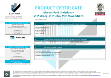
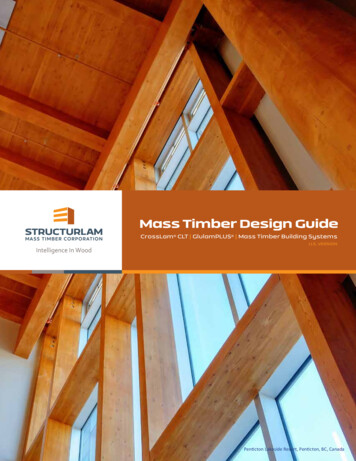
Common Timber Truss TypesTFEC 4-2020Page 6
Truss AnalysisIdeal TrussesTrusses are structural assemblies that respond to applied loads with pure axial compression or tensionin their members. The top and bottom truss members are called chords and the members between thechords are called web members. Web members that are in axial compression are called struts. Webmembers that are in axial tension are called ties.In an ideal truss, members meet at nodes or joints (also called panel points) that are idealized as hingesor pins that are incapable of transmitting bending moments. Loads are applied to an ideal truss only atits nodes. Applying loads (and supports) only at nodes keeps the truss members shear-free. It helps,too, that ideal truss analysis tended to neglect member self-weight. The centroidal axes of all trussmembers meeting at a node converge to a discrete point.Classical methods of analyzing trusses are only valid for ideal trusses, and real-world timber trusses arenot very idealistic. Real trusses respond to applied loads with a combination of axial stress, bendingmoments, and shear in their members. Real trusses often have continuous chords that are not pinned atthe joints and loads are often applied along the length of the chords. It is also common to intentionallyintroduce eccentricities into truss joints for more efficient joinery.TFEC 4-2020Page 7
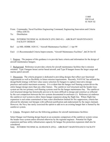
Not all structural elements that look like trusses actually perform as trusses. To qualify as a true truss, itmust be capable of responding to loads applied at the nodes predominately with axial stresses in itsmembers. If significant bending moments and shear forces are introduced into the members, it is not atrue truss. For instance, a hammer-beam truss behaves very little like a truss. Similarly, a queen-posttruss is not always a true trussThe truss shown below from the roof of the First Congregational Church in Canterbury, Connecticut, isnot a true truss - it is a mongrel. The diagonal struts transfer roof loads to the bottom chord where theyare resisted by bending. This is a blatant case of a carpenter’s failed structural intuition.Source: Early Connecticut Meetinghouses by J. Frederick Kelly, 1948TFEC 4-2020Page 8
Classical MethodsIt has been said that an engineer only truly understands the behavior of a structure when he can analyzeit on the back of a napkin or envelope. Classical methods of truss analysis are simple and reliable. Allthat you need is a pencil, a calculator, and of course, a napkin.There are actually two classical methods for analyzing trusses – the Method of Joints, and the Method ofSections. Sadly, few engineering schools still teach these methods to their students. The principles aresimilar for both methods. A free-body diagram is constructed for each individual truss joint or a portionof a truss. The truss axial forces are algebraically solved to satisfy static equilibrium.Classical methods are only valid for ideal trusses, so if you happen to be engineering a real truss with acontinuous top chord supporting distributed loads, it becomes a two-step process. The first step is toanalyze the top chord as a continuous beam with each truss joint treated as a rigid support. This willreveal the bending moments and shear in the top chord. As the struts and other web members arethemselves elastic structures, this represents an approximation; an excellent one, but nonethelessimperfect. The second step is to apply the beam reactions from step one to an ideal truss as point loadsat the joints. Then analyze the truss by one of the classical methods.For a statically determinate truss, the analysis seldom takes an experienced engineer more than 10minutes. As engineering practice has evolved to take advantage of computer methods, thoseidealizations can be set aside with models that incorporate the elastic properties of the members toprovide more realistic answers. Nevertheless, hand calculations are a good check on a computer modeland will quickly identify if there was an error in the modeling.TFEC 4-2020Page 9
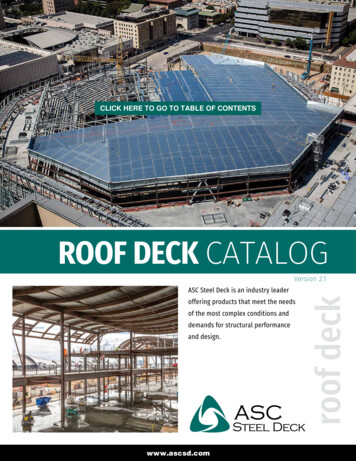
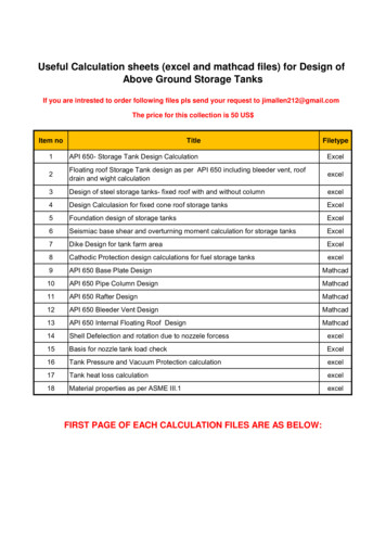
Graphical MethodAt one time, the most common method of analyzing a truss was a graphical method referred to as aMaxwell Stress Diagram. This method harkens to an age when engineers drafted the drawings for theirstructures and sat at drafting tables. The stress diagram for each load case would be included on thetruss drawings and was often required by the Building Official. The axial force in each truss membercould be determined by scaling the length of the line representing a particular truss member in thestress diagram.The Maxwell stress diagram was a very quick and efficient method once you mastered the technique.The popularity of the method faded in the 1970s with the introduction of the handheld calculator. Oncepersonal computers and cheap analytical software were introduced in the 1980s, the method becameextinct.Timber Roof Truss drawing with Maxwell stress diagrams. Source: The Design of Simple Roof Trusses inWood and Steel by Malverd A. Howe, 1903TFEC 4-2020Page 10
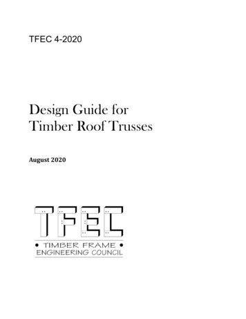
Squire Whipple (1804-1888)No authoritative treatise on trusses can fail to pay homage to SquireWhipple, who wrote the book on rational calculation of forces andstresses in trusses. In 1830, after graduating from Union College,Schenectady, NY, Whipple conducted surveys for several railroad andcanal projects and made surveying instruments. In 1840 he invented alock for weighing canal boats. In the next years he turned hisattention to bridges and invented two new truss designs employingiron as well as timber. In 1853 he completed an iron railroad bridge of146-foot (44-metre) span near West Troy (now Watervliet), NY. In thefollowing year appeared his Work on Bridge Building, the firstsignificant attempt to supply a theoretical means for calculatingstresses in place of the rule-of-thumb methods then in generalpractice. The book, which he expanded and personally printed in 1869under the title An Elementary and Practical Treatise on BridgeBuilding, facilitated the rational use of wrought and cast iron and waswidely used in railroad engineering for decades.TFEC 4-2020Page 11
Computer ModelingThere are currently several softwareoptions available for truss analysis, manyof which also incorporate moresophisticated Finite Element Analysis(FEA) and even dynamic and non-linearmodeling. The intense modeling involvedin most FEA software tends to be overkillfor the vast majority of timber trusses,particularly when compared to usingmethod of sections to quickly findmember axial loads by hand. Much aswith drafting, analytical effort performedon the computer does aid in quickrevisions, detailed record keeping, andinvestigating the structural complexitythat commonly arises in modern design.A truss can be easily and accurately modeled in two dimensions, but three-dimensional analysis ishelpful when several similar trusses resist more than just vertical gravity loads - a common situation inopen frame pavilions or where a truss serves to drag a lateral force between two shear wall segments.Ultimately, truss analysis software should be viewed as a tool available for developing proper membersizing and axial loads, which can be used for detailing joinery and specifying fasteners. Like all tools,operator knowledge, experience, and attention to detail are paramount for accurate and meaningfulstructural analysis with computer software. As with any powerful tool, in the wrong hands, structuralanalysis software can be rather dangerous.Determining the boundary conditions supporting the model are an extremely important first step inanalyzing any timber truss. A true truss resolves all outward thrust or horizontal forces internally; notrelying on support reactions. This means that gravity loading usually results in only vertical loadreactions at the truss bearing points. Just as with performing a beam analysis, the truss is usuallymodeled as sitting on a pin support on one end and a roller support on the other. Setting the model ona pin/pin connection suggests that the truss is sitting within two figurative canyon walls, which wouldyield erroneous member forces, particularly for a scissor truss.Once the member is either modeled within the software or imported from a BIM model, care should betaken to confirm that all members are the correct species, grade, size and orientation. It is also a goodidea to confirm that the software's preset design characteristics for a selected species are accurate.Review of the preset material unit density is important, since it can significantly affect the self-weightdead loads.Similar to structural boundary conditions at supports, member end fixities should be reviewed as well.As mentioned earlier, all joints are usually analyzed as a hinge or pinned connection, even though mostmortise and tenon joints do provide some moment fixity, and might most accurately be modeled asTFEC 4-2020Page 12
springs. There is some variation in how connections are labeled between software platforms, butultimately all joints should be free to rotate. Continuous members that pass-through nodes will alsoneed to be identified at this point. Some software makes each member segment independent, requiringthe analysis to fix any midspan nodes to represent a continuous member. Other software recognizescontinuous members if the member center line is drawn continuously through the node. The lattermethod can become an issue if the center line model is imported as a CAD file, as continuous lines aretypically lost in the importing process, resulting in segmenting all members at every node.Similar to analytical calculation methods performed by hand, computer software generally requires thatdiagrams be drawn as center line models if drawn within the program itself. This certainly aids insimplifying the analysis and future modification of member dimensions, but it can be problematic increating an accurate depiction of the realistic load paths through the truss. This is typically a biggerhurdle when performing three-dimensional analysis of full timber frames that incorporates trusses,rather than in the simple review of a single two-dimensional truss. Stacked timber connections orcontinuous perpendicular members bisecting truss elements, are common sources of this dilemma, andoften require finessing of the node locations with an understanding of probable axial loading.Many analysis programs provide a member offset function to handle the stacked timber connections,while maintaining proper member planes for area loading. But bisecting members, such as continuouseave and ridge beams which have become more common place in modern designs, particularly forsupporting gable overhangs, present a significant trap during analysis. Modeling software typically has adifficult time distinguishing when truss axial load path has been broken, and often will continue toanalyze the elements as an idealized or real truss even when members are not even joined together.But because the center line modeled members share a common node, the software has a difficult timedistinguishing a break in the truss continuity. This tendency is likely a result of most software's multiplematerial platform, as these types of axial load transferring through bisecting members is much lessproblematic in steel and concrete, than when dealing with the nuances and design capacities of wood.A common example to better illustrate this point is a king-post truss versus a structural ridge supportedby a segmented central post and a full span header. When initially modeled in a structural softwareboth frames will look and analyze similarly unless additional steps are taken. In this scenario thestructural ridge will likely simply load the mid-post in compression, but the analysis might often continueto show the post in tension, similar to a king-post in the true truss. This can be simply resolved byrestricting members, such as the mid-post to compression only. Failing to recognize this flawed modelglitch would create a significant misrepresentation of the realistic load path in the analysis. Part of thekey to truly understanding and performing accurate software analysis is to clearly understand when alabeled truss isn't really a truss at all.TFEC 4-2020Page 13
Example of a real king-post trusssupporting a distributed purlin roofload. The offset and non-bisectedjoinery aids in computer modeling.The upward thrust of the raftersopposing the compression of thediagonal struts forcing the king-postinto tension.An example of structural ridgesupported by a segmented post and afull span header. Many computerprograms have a difficult timedistinguishing this as a non-truss,particularly if the header is broughtup to the same plane as the eaveplate. A key warning sign is the axialloading of the segmented mid-post.If the program suggest that it istension a closer look and resultingmanipulation is required.TFEC 4-2020Page 14
The move toward better integration between Building Information Modeling (BIM) design models andstructural analytical software might reduce these types of misrepresentations, but will also inevitablycreate new hurdles to be discovered and cleared. As with all tools, a good prior understanding of theexpected results will go a long way toward proper use and accurate analysis. Being able to step backand take a deeper dive into a result that does follow truss expectations is key to truly unlocking the fullpotential of the various software platforms.Aside from proprietary engineering templates created by individual firms, there is no commerciallyavailable software that will analyze or design timber connections. When engineering timber trusses, thecomputer modeling or hand calculations to determine member forces is the easy part. The design of thetruss connections is the real challenge. Connection engineering must be done by hand and requires nosmall measure of experience and ingenuity.TFEC 4-2020Page 15
Truss Deflection and CamberMethods for calculating truss deflections were developed that could be readily done “by hand.” Theyrelied on the concept of “virtual work” and could isolate one particular deflection, at one particularnode, corresponding to a “virtual load” applied at that node. While computers generate a much widerarray of truss deflections under load, almost none of the software includes any distortion at theconnections. Modeling the connections as springs adds enough work and uncertainty as to make it veryrare. This is not to say, though, that slip and crushing at connections do not influence truss deflection.Some older texts acknowledge this and offer unsatisfying, but real, suggestions to double the deflectioncaused by axial stretch and shortening in the members.Cambering trusses is an arcane but crucial topic. Early truss patents – notably the Long – included thisability as a significant feature. Wedges and shims were intended to prestress the internal components,reducing their forces when under design loading. Threaded rods, in Pratt trusses, make for readyadjustment of the truss sag – even as it increases while dead load is being added. The recommendedtruss camber offered in Heavy Timber Construction (1963) is K1L3/H K2L2/H, where the camber ismeasured in inches, at the center of truss. L is span in feet; H is height of truss in feet, at center; K 1 0.000032 for any type of truss; K2 0.0028 for flat or pitched trusses or 0.00063 for bowstring trusses(that is trusses without splices in upper chord).TFEC 4-2020Page 16
Development of Truss FormsAs many truss designs have their origin in early timber bridges, their names are better explained first bystarting a discussion of parallel-chord trusses.To illustrate, we start with two parallel chords, withverticals that subdivide the span into generally identicalrectangles.Under load, each of these rectangular sections distorts,with one diagonal becoming shorter and the otherbecoming longer. In this case, if we assume all of theapplied loads are the same, only the middle bay remainsundistorted. If there IS a middle bay. Even numbers of bays avoid this.Two truss types – Howe and Pratt – resolve to preventthis distortion in opposite ways. In a Howe truss,diagonal web members are introduced to prevent theopposing corners of each bay from getting closer to oneanother. The result is diagonal members in compression.As the middle bay will only be loaded – and tend todistort – if the loading is unbalanced, it is typical to see aHowe truss with only an even number of bays, or withdiagonals in both directions at the center span:Where the diagonals will be in compression, these members must be stout enough to resist buckling,and so timber trusses of the Howe type include timber diagonals. As this results in the vertical membersacting in tension, with the advent of iron and steel, it is common to see steel or iron rods as verticals,and this results in an aesthetic that emphasizes the diagonals.Conversely, one could prevent the corners of eachsquare bay from getting farther apart by tying thecorners together with web members that would be intension. This is how the Pratt Truss works. Further, asdiagonal web members in tension can be thin – they donot have to resist buckling – the Pratt Truss oftenemploys steel or iron rods as diagonal web members.This results in compression in the vertical members,requiring timber members stout enough to resist buckling, and the resulting aesthetic emphasizes theverticals with light-weight diagonals. As an added bonus, the verticals are shorter than the diagonals, soshorter timbers are permissible. Further, as the vulnerability to buckling is decreased for shortermembers, the verticals can typically be smaller than they would have to be if they were orienteddiagonally. Finally, it is fairly straightforward to detail a joint between wood members when they meetat right angles. For these reasons, a Pratt Truss is often a good choice where a parallel-chord truss isdesired.TFEC 4-2020Page 17
A Warren Truss deviates from both the Howe and Prattby foregoing vertical web members, favoring instead, asimple zig-zagging diagonal pattern. In a Warren Truss,the outer diagonals are in compression and the innerones are in tension. If steel or iron rods are used for theweb members in tension, the resulting aesthetic mayreflect this.Finally, and especially for those who look at covered timber bridges, the most familiar patented truss islikely the Town Lattice Truss. In addition to their widespread use in covered bridges, these trusses canbe found supporting town hall and other building roofs. At present, approximately half of the extantcovered bridges in Vermont rely upon Town LatticeTrusses. One way of looking at a Town Lattice is toimagine superimposing three or more WarrenTrusses on top of one another as so:With this as background, in the case of roof trusses with sloping top chords, some of the names given tothe truss forms are slightly different from those assigned to the parallel-chord versions described here.However, this may serve as background for later chapters on each roof truss type.Worrall covered bridge in Rockingham, Vermont. The Town Lattice truss was patented in 1820 by IthielTown, a prominent architect from Connecticut. Town never actually built a bridge himself, but he soldthe rights to use his design to covered bridge builders. He charged a royalty of one dollar for every footof bridge span. If he caught someone building a Town Lattice bridge without having purchased the rightsto the design, he would impose a penalty of two dollars per foot of span.TFEC 4-2020Page 18
TFEC 4-2020Page 19
TFEC 4-2020Page 20
King-Post TrussesThe king-post truss is the most commontruss form for short span applications.King-post trusses are those with aprincipal vertical web member at thecenter of the span. Some havesuggested that a king-post truss musthave a heavy timber in that verticalposition and if a steel rod is usedinstead of a timber, it is no longer considered a true king-post truss.A king-post truss used for a short bridge would typically be loaded along the bottom chord, possibly witha transverse beam connected to the baseof the king post. In a roof truss,however, roof loads are typically appliedto the top chord through purlins orstructural panels. In such instances, theking post is a zero-stress member andonly serves to carry the dead load of thebottom chord unless there are loadsapplied to the bottom chord. If the kingpost truss is modified to include diagonalstruts or braces, the roof loads applied to the top chord are transferred to the king-post which becomesa tension member. The modified version of a king-post truss – as shown at left – may at once be called aking-post truss with braces, but may also be referred to as a Howe truss.In the diagram shown above, the king post is a timber, and the top has been shaped to fit between thetop chords in a manner resembling the keystone in an arch.King-post pony truss bridge. The roadway issupported by a cross beam that is suspendedfrom the king-post.TFEC 4-2020Page 21
Example of a king-post truss supporting a CLT roof deckTFEC 4-2020Page 22
Queen-Post TrussesWith similar origins in bridges, thequeen-post truss is notable for havingtwo principal verticals instead of thesingle for which the king-post gets itsname.However, unless the interior rectangle isbraced with one or two diagonals, thequeen post truss is not really a truss, but a frame, where the interior rectangle can distort underasymmetric loading. Although this diagram shows aqueen post in a gabled-roof shape, it is not uncommonto find a queen post truss without the sloping upperchords, as shown at left. It is common to have purlinsaligned with the queen-posts supporting the roofstructure.Typically, a queen post truss may be desired where there is to be an open area under the roof – a loft orattic. As such, there is likely a distributed load acting on the bottom chord and this must be sizedaccordingly for bending. Where the principal rafters extend to the peak, and under uniform andsymmetric loading, the presence of the mid-height crossing member helps support the sloping topchords but increases the tie force in the bottom chord. Under wind load or asymmetric snow load,however, the lack of diagonals in the interior rectangle causes an increase in bending in the bottomchord. It is this induced bending that explains why a queen post truss is not really a truss.TFEC 4-2020Page 23
Example of a queen-post trusssupporting the second-floor structureof a barn to provide a column freespace below. Purlins supporting roofrafters rest on the queen-posts.TFEC 4-2020Page 24
Howe TrussesThe Howe truss, patented by WilliamHowe in 1840, is the most popular,practical, and efficient truss form formoderate span applications. In itssimplest form it is really a modifiedking-post truss. The Howe truss ischaracterized by diagonal compressionstruts and vertical tension members.The advantage of a Howe Truss for use in a roof derives from the efficiency of using steel rods as thetension members. However, in the diagram above, the tension members to both sides of the middletheoretically carry no force unless the bottom chord is loaded – for example, by a ceiling or an atticfloor. Even in the absence of loads applied directly to the bottom-chord, these rods may help supportthe self-weight of the bottom chord. For structural efficiency, the slope of the diagonal struts shouldmatch the roof slope.TFEC 4-2020Page 25
Pratt TrussesAs noted above, a Pratt Truss resolves the need for triangulation through the combination of diagonalmembers in tension and vertical members in compression.The advantage of a Pratt Truss for use in a roof derives in part from the efficiency of using steel rods asthe tension members. Further, by shortening the compression web members, these elements cangenerally be smaller in cross-section than those used in a Howe Truss. Unfortunately, and especially fora roof truss with sloping top chords, the vertical web members meet the top chord at an angle, makingthe design of these joints complicated. It is likely that a Pratt Truss is better suited to use as a parallelchord structure.TFEC 4-2020Page 26
Fink TrussesThe Fink truss is a practical truss form forlong-span applications. The majoradvantage of a Fink is that each half of thetruss can be fully assembled in the shopand shipped to the site for final assembly.In some instances, the bottom chords canbe sloped similar to a scissor truss forarchitectural drama.Compound Fink truss made up of twosmaller trusses joined in the field.TFEC 4-2020Page 27
Scissor TrussThe scissor truss is a structurallyinefficient truss form that is verypopular with architects and timberframe patrons. Much like the reviledand troublesome “raised bottom chordtruss” (known as “rafter buster” morecolloquially), scissors trusses can add tothe open feeling of a space, by raising the lowest member above the most effective location – at theeave line. Characterized by sloping bottom chords that cross at mid-span, a scissor truss allows for anelevated ceiling. In early Gothic Cathedrals, where the masonry vaulting extended above the height ofthe side walls, the scissor truss made room for the vaulting by liberating the space where a horizontal,eave-level bottom chord would have interfered with the perceived stone ceiling.In considering the behavior of a scissor truss, the most important attribute is likely the change in l
Free Body Diagram 49 Steel Side Plates 50 Hardwood Pegs 53 Nuts and Bolts 55 Ogee Washers 57 . TFEC 4-2020 Page 4 Split Rings and Shear Plates 58 . Whipple, who wrote the book on rational calculation of forces and stresses in trusses. In 1830, after graduating from Union College, Schenectad