Transcription
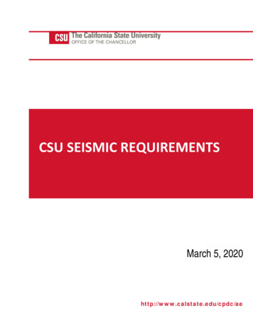
P1: JsYASCE003-12.texASCE003/SIE-v1.clsOctober 15, 2005Chapter 12SEISMIC DESIGN REQUIREMENTS FOR BUILDING STRUCTURES12.1 STRUCTURAL DESIGN BASIS12.1.1 Basic Requirements. The seismic analysis and designprocedures to be used in the design of building structures and theircomponents shall be as prescribed in this section. The buildingstructure shall include complete lateral and vertical force-resistingsystems capable of providing adequate strength, stiffness, and energy dissipation capacity to withstand the design ground motionswithin the prescribed limits of deformation and strength demand.The design ground motions shall be assumed to occur along anyhorizontal direction of a building structure. The adequacy of thestructural systems shall be demonstrated through the constructionof a mathematical model and evaluation of this model for the effects of design ground motions. The design seismic forces, andtheir distribution over the height of the building structure, shall beestablished in accordance with one of the applicable proceduresindicated in Section 12.6 and the corresponding internal forcesand deformations in the members of the structure shall be determined. An approved alternative procedure shall not be used toestablish the seismic forces and their distribution unless the corresponding internal forces and deformations in the members aredetermined using a model consistent with the procedure adopted.EXCEPTION: As an alternative, the simplified design procedures ofSection 12.14 is permitted to be used in lieu of the requirements of Sections12.1 through 12.12, subject to all of the limitations contained in Section12.14.12.1.2 Member Design, Connection Design, and Deformation Limit. Individual members, including those not part of theseismic force–resisting system, shall be provided with adequatestrength to resist the shears, axial forces, and moments determinedin accordance with this standard, and connections shall developthe strength of the connected members or the forces indicated inSection 12.1.1. The deformation of the structure shall not exceedthe prescribed limits where the structure is subjected to the designseismic forces.12.1.3 Continuous Load Path and Interconnection. A continuous load path, or paths, with adequate strength and stiffness shallbe provided to transfer all forces from the point of application tothe final point of resistance. All parts of the structure between separation joints shall be interconnected to form a continuous path tothe seismic force–resisting system, and the connections shall becapable of transmitting the seismic force (F p ) induced by the partsbeing connected. Any smaller portion of the structure shall be tiedto the remainder of the structure with elements having a designstrength capable of transmitting a seismic force of 0.133 timesthe short period design spectral response acceleration parameter, S DS , times the weight of the smaller portion or 5 percent ofthe portion’s weight, whichever is greater. This connection forcedoes not apply to the overall design of the seismic force–resistingsystem. Connection design forces need not exceed the maximumforces that the structural system can deliver to the connection.12.1.4 Connection to Supports. A positive connection for resisting a horizontal force acting parallel to the member shallbe provided for each beam, girder, or truss either directly to itsMinimum Design Loads for Buildings and Other Structuressupporting elements, or to slabs designed to act as diaphragms.Where the connection is through a diaphragm, then the member’ssupporting element must also be connected to the diaphragm. Theconnection shall have a minimum design strength of 5 percent ofthe dead plus live load reaction.12.1.5 Foundation Design. The foundation shall be designed toresist the forces developed and accommodate the movements imparted to the structure by the design ground motions. The dynamicnature of the forces, the expected ground motion, the design basis for strength and energy dissipation capacity of the structure,and the dynamic properties of the soil shall be included in thedetermination of the foundation design criteria. The design andconstruction of foundations shall comply with Section 12.13.12.1.6 Material Design and Detailing Requirements. Structural elements including foundation elements shall conform to thematerial design and detailing requirements set forth in Chapter 14.12.2 STRUCTURAL SYSTEM SELECTION12.2.1 Selection and Limitations. The basic lateral and verticalseismic force–resisting system shall conform to one of the typesindicated in Table 12.2-1 or a combination of systems as permittedin Sections 12.2.2, 12.2.3, and 12.2.4. Each type is subdivided bythe types of vertical elements used to resist lateral seismic forces.The structural system used shall be in accordance with the seismicdesign category and height limitations indicated in Table 12.2-1.The appropriate response modification coefficient, R, systemoverstrength factor, 0 , and the deflection amplification factor,Cd , indicated in Table 12.2-1 shall be used in determining thebase shear, element design forces, and design story drift.The selected seismic force-resisting system shall be designedand detailed in accordance with the specific requirements for thesystem per the applicable reference document and the additionalrequirements set forth in Chapter 14.Seismic force–resisting systems that are not contained inTable 12.2-1 are permitted if analytical and test data are submittedthat establish the dynamic characteristics and demonstrate the lateral force resistance and energy dissipation capacity to be equivalent to the structural systems listed in Table 12.2-1 for equivalentresponse modification coefficient, R, system overstrength coefficient, 0 , and deflection amplification factor, Cd , values.12.2.2 Combinations of Framing Systems in Different Directions. Different seismic force–resisting systems are permitted tobe used to resist seismic forces along each of the two orthogonal axes of the structure. Where different systems are used,the respective R, Cd , and 0 coefficients shall apply to eachsystem, including the limitations on system use contained inTable 12.2-1.12.2.3 Combinations of Framing Systems in the Same Direction. Where different seismic force–resisting systems are usedin combination to resist seismic forces in the same direction ofstructural response, other than those combinations considered as11917:48
P1: JsYASCE003-12.texASCE003/SIE-v1.clsOctober 15, 2005TABLE 12.2-1 DESIGN COEFFICIENTS AND FACTORS FOR SEISMIC FORCE–RESISTING SYSTEMSStructural System Limitationsand Building Height (ft) LimitcSeismic Force–Resisting SystemASCE 7 Section whereDetailing Requirementsare SpecifiedResponseModificationCoefficient, RaSystemOverstrengthFactor, Ω0 gDeflectionAmplificationFactor, Cd bSeismic Design CategoryBA. BEARING WALL SYSTEMS1. Special reinforced concrete shear walls2. Ordinary reinforced concrete shearwalls3. Detailed plain concrete shear walls4. Ordinary plain concrete shear walls5. Intermediate precast shear walls6. Ordinary precast shear walls7. Special reinforced masonry shear walls8. Intermediate reinforced masonry shearwalls9. Ordinary reinforced masonry shearwalls10. Detailed plain masonry shear walls11. Ordinary plain masonry shear walls12. Prestressed masonry shear walls13. Light-framed walls sheathed withwood structural panels rated for shearresistance or steel sheets14. Light-framed walls with shear panelsof all other materials15. Light-framed wall systems using flatstrap bracingB. BUILDING FRAME SYSTEMS1. Steel eccentrically braced frames,moment resisting connections atcolumns away from links2. Steel eccentrically braced frames,non-moment-resisting, connections atcolumns away from links3. Special steel concentrically bracedframes4. Ordinary steel concentrically bracedframes5. Special reinforced concrete shear walls6. Ordinary reinforced concrete shearwalls7. Detailed plain concrete shear walls8. Ordinary plain concrete shear walls9. Intermediate precast shear walls10. Ordinary precast shear walls11. Composite steel and concreteeccentrically braced frames12. Composite steel and concreteconcentrically braced frames13. Ordinary composite steel and concretebraced frames14. Composite steel plate shear walls15. Special composite reinforced concreteshear walls with steel elements16. Ordinary composite reinforcedconcrete shear walls with steelelements17. Special reinforced masonry shear walls18. Intermediate reinforced masonry shearwalls19. Ordinary reinforced masonry shearwalls20. Detailed plain masonry shear walls21. Ordinary plain masonry shear walls12014.2 and 14.2.3.614.2 and 14.2.3.45421/221/25414.2 and 14.2.3.214.2 and 14.2.3.114.2 and 14.2.3.514.2 and 14.2.3.314.4 and 14.4.314.4 and 414.414.414.1, 14.1.4.2,and 14.5CDdEdFeNL NL 160 160NL NL NP NP100NP211/24331/221/4NLNLNLNLNLNLNP NPNP NPNL 40kNP NPNL 160NL NPNPNP40kNP160NPNPNP40kNP100NP21/213/4NL 160 LNL14.1, 14.1.4.2,and 14.514.1, 14.1.4.2,and 14.5221/2414.1NPNPNPNLNPNPNP65NPNPNP65NPNPNP652NL NL35NPNP231/2NL NL656565824NL NL 160 16010014.1724NL NL 160 16010014.1625NL NL 160 16010014.131/4231/4NL NL 35 j35 jNP j14.2 and 14.2.3.614.2 and 14.2.3.46521/221/2541/2NL NL 160 160NL NL NP NP100NP14.2 and 14.2.3.214.2 and 14.2.3.114.2 and 14.2.3.514.2 and NLNLNLNLNPNP40kNP160NPNP40kNP10014.35241/2NL NL 160 16010014.3323NL NLNPNP14.314.361/2621/221/251/25NL NL 160 160NL NL 160 16010010014.3521/241/2NL NLNPNP14.414.451/2421/221/244NL NL 160 160NL NL NP NP100NP14.4221/22NL 160 NPNPNP14.414.4211/221/221/2211/4NL NPNL NPNPNPNPNPNP NPNP NPNL 40kNP NPNL 160NPNPNPNPASCE 7-0517:48
P1: JsYASCE003-12.texASCE003/SIE-v1.clsOctober 15, 2005TABLE 12.2-1 DESIGN COEFFICIENTS AND FACTORS FOR SEISMIC FORCE–RESISTING SYSTEMS (continued)Structural System Limitationsand Building Height (ft) LimitcSeismic Force–Resisting System22. Prestressed masonry shear walls23. Light-framed walls sheathed withwood structural panels rated for shearresistance or steel sheets24. Light-framed walls with shear panelsof all other materials25. Buckling-restrained braced frames,non-moment-resisting beam-columnconnections26. Buckling-restrained braced frames,moment-resisting beam-columnconnections27. Special steel plate shear wallC. MOMENT-RESISTING FRAMESYSTEMS1. Special steel moment frames2. Special steel truss moment frames3. Intermediate steel moment frames4. Ordinary steel moment frames5. Special reinforced concrete momentframes6. Intermediate reinforced concretemoment frames7. Ordinary reinforced concrete momentframes8. Special composite steel and concretemoment frames9. Intermediate composite momentframes10. Composite partially restrained momentframes11. Ordinary composite moment framesD. DUAL SYSTEMS WITH SPECIALMOMENT FRAMES CAPABLE OFRESISTING AT LEAST 25% OFPRESCRIBED SEISMIC FORCES1. Steel eccentrically braced frames2. Special steel concentrically bracedframes3. Special reinforced concrete shear walls4. Ordinary reinforced concrete shearwalls5. Composite steel and concreteeccentrically braced frames6. Composite steel and concreteconcentrically braced frames7. Composite steel plate shear walls8. Special composite reinforced concreteshear walls with steel elements9. Ordinary composite reinforcedconcrete shear walls with steelelements10. Special reinforced masonry shear walls11. Intermediate reinforced masonry shearwalls12. Buckling-restrained braced frame13. Special steel plate shear wallsASCE 7 Section whereDetailing Requirementsare SpecifiedResponseModificationCoefficient, RaSystemOverstrengthFactor, Ω0 gDeflectionAmplificationFactor, Cd bSeismic Design CategoryBCDdEdFe14.414.1, 14.1.4.2,and 14.511/2721/221/213/441/2NLNLNPNLNP65NP65NP6514.1, 14.1.4.2,and 4.1821/25NLNL16016010014.1726NLNL16016010014.1 and 12.2.5.514.112.2.5.6, 12.2.5.7,12.2.5.8, 12.2.5.9,and 14.112.2.5.6, 12.2.5.7,12.2.5.8, and 14.112.2.5.5 and 14.2874.533351/251/24NLNLNLNL NL NLNL 160 100NL 35h,i 41/2NLNLNPNPNP14.23321/2NLNPNPNPNP12.2.5.5 and 160 NL12.2.5.1Minimum Design Loads for Buildings and Other Structures12117:48
P1: JsYASCE003-12.texASCE003/SIE-v1.clsOctober 15, 2005TABLE 12.2-1 DESIGN COEFFICIENTS AND FACTORS FOR SEISMIC FORCE–RESISTING SYSTEMS (continued)Structural System Limitationsand Building Height (ft) LimitcSeismic Force-Resisting SystemASCE 7 Section whereDetailing Requirementsare SpecifiedResponseModificationCoefficient, RaSystemOverstrengthFactor, Ω0 gDeflectionAmplificationFactor, Cd bSeismic Design CategoryDdEdFe35NPNPh,kNL NL 160NL 160 NP100NP100NPNL NLNPNPNPBE. DUAL SYSTEMS WITHINTERMEDIATE MOMENT FRAMESCAPABLE OF RESISTING AT LEAST25% OF PRESCRIBED SEISMICFORCES1. Special steel concentrically bracedframes f2. Special reinforced concrete shear walls3. Ordinary reinforced masonry shearwalls4. Intermediate reinforced masonry shearwalls5. Composite steel and concreteconcentrically braced frames6. Ordinary composite braced frames7. Ordinary composite reinforcedconcrete shear walls with steelelements8. Ordinary reinforced concrete shearwallsF. SHEAR WALL-FRAMEINTERACTIVE SYSTEM WITHORDINARY REINFORCEDCONCRETE MOMENT FRAMES ANDORDINARY REINFORCEDCONCRETE SHEAR WALLSG. CANTILEVERED COLUMNSYSTEMS DETAILED TO CONFORMTO THE REQUIREMENTS FOR:1. Special steel moment frames2. Intermediate steel moment frames3. Ordinary steel moment frames4. Special reinforced concrete momentframes5. Intermediate concrete moment frames6. Ordinary concrete moment frames7. Timber .431/23314.351/221/241/2NL NL 160100NP14.314.331/2521/23341/2NL NLNL NLNPNPNPNPNPNP14.251/221/241/2NL NLNPNPNP12.2.5.10 and 14.241/221/24NL NPNPNPNP12.2.5.5 and 14.114.114.112.2.5.5 and /23535353535353535353535h NPh,iNP 235353535NP35NPNP35NL NL12.2.5.2NPNPNP35NPh,iNPh,i35NPNPNPH. STEEL SYSTEMS NOT14.1333NL NL NP NPNPSPECIFICALLY DETAILED FORSEISMIC RESISTANCE, EXCLUDINGCANTILEVER COLUMN SYSTEMSa Response modification coefficient, R, for use throughout the standard. Note R reduces forces to a strength level, not an allowable stress level.b Reflection amplification factor, C , for use in Sections 12.8.6, 12.8.7, and 12.9.2dc NL Not Limited and NP Not Permitted. For metric units use 30.5 m for 100 ft and use 48.8 m for 160 ft. Heights are measured from the base of the structureas defined in Section 11.2.d See Section 12.2.5.4 for a description of building systems limited to buildings with a height of 240 ft (73.2 m) or less.e See Section 12.2.5.4 for building systems limited to buildings with a height of 160 ft (48.8 m) or less.f Ordinary moment frame is permitted to be used in lieu of intermediate moment frame for Seismic Design Categories B or C.g The tabulated value of the overstrength factor, , is permitted to be reduced by subtracting one-half for structures with flexible diaphragms, but shall not be0taken as less than 2.0 for any structure.h See Sections 12.2.5.6 and 12.2.5.7 for limitations for steel OMFs and IMFs in structures assigned to Seismic Design Category D or E.i See Sections 12.2.5.8 and 12.2.5.9 for limitations for steel OMFs and IMFs in structures assigned to Seismic Design Category F.j Steel ordinary concentrically braced frames are permitted in single-story buildings up to a height of 60 ft (18.3 m) where the dead load of the roof does notexceed 20 psf (0.96 kN/m2 ) and in penthouse structures.k Increase in height to 45 ft (13.7 m) is permitted for single story storage warehouse facilities.dual systems, the more stringent system limitation contained inTable 12.2-1 shall apply and the design shall comply with therequirements of this section.12.2.3.1 R, Cd , and Ω0 Values for Vertical Combinations. Thevalue of the response modification coefficient, R, used for designat any story shall not exceed the lowest value of R that is usedin the same direction at any story above that story. Likewise, the122deflection amplification factor, Cd , and the system over strengthfactor, 0 , used for the design at any story shall not be less thanthe largest value of this factor that is used in the same directionat any story above that story.EXCEPTIONS:1. Rooftop structures not exceeding two stories in height and 10 percentof the total structure weight.ASCE 7-0517:48
P1: JsYASCE003-12.texASCE003/SIE-v1.cls2. Other supported structural systems with a weight equal to or lessthan 10 percent of the weight of the structure.3. Detached one- and two-family dwellings of light-frame construction.A two-stage equivalent lateral force procedure is permitted tobe used for structures having a flexible upper portion above a rigidlower portion, provided that the design of the structure complieswith the following:a. The stiffness of the lower portion must be at least 10 timesthe stiffness of the upper portion.b. The period of the entire structure shall not be greater than1.1 times the period of the upper portion considered as aseparate structure fixed at the base.c. The flexible upper portion shall be designed as a separatestructure using the appropriate values of R and ρ.d. The rigid lower portion shall be designed as a separate structure using the appropriate values of R and ρ. The reactionsfrom the upper portion shall be those determined from theanalysis of the upper portion amplified by the ratio of theR/ρ of the upper portion over R/ρ of the lower portion. Thisratio shall not be less than 1.0.12.2.3.2 R, Cd , and Ω0 Values for Horizontal Combinations.Where a combination of different structural systems is utilized toresist lateral forces in the same direction, the value of R used fordesign in that direction shall not be greater than the least valueof R for any of the systems utilized in that direction. Resistingelements are permitted to be designed using the least value of R forthe different structural systems found in each independent line ofresistance if the following three conditions are met: (1) OccupancyCategory I or II building, (2) two stories or less in height, and (3)use of light-frame construction or flexible diaphragms. The valueof R used for design of diaphragms in such structures shall not begreater than the least value for any of the systems utilized in thatsame direction.The deflection amplification factor, Cd , and the system overstrength factor, 0 , in the direction under consideration at anystory shall not be less than the largest value of this factor for theR factor used in the same direction being considered.12.2.4 Combination Framing Detailing Requirements. Structural components common to different framing systems used toresist seismic motions in any direction shall be designed usingthe detailing requirements of Chapter 12 required by the highestresponse modification coefficient, R, of the connected framingsystems.12.2.5 System Specific Requirements. The structural framingsystem shall also comply with the following system specific requirements of this section.12.2.5.1 Dual System. For a dual system, the moment framesshall be capable of resisting at least 25 percent of the designseismic forces. The total seismic force resistance is to be providedby the combination of the moment frames and the shear walls orbraced frames in proportion to their rigidities.12.2.5.2 Cantilever Column Systems. Cantilever column systems are permitted as indicated in Table 12.2-1 and as follows.The axial load on individual cantilever column elements calculated in accordance with the load combinations of Section 2.3shall not exceed 15 percent of the design strength of the columnto resist axial loads alone, or for allowable stress design, the axialload stress on individual cantilever column elements, calculatedin accordance with the load combinations of Section 2.4 shall notexceed 15 percent of the permissible axial stress.Minimum Design Loads for Buildings and Other StructuresOctober 15, 2005Foundation and other elements used to provide overturningresistance at the base of cantilever column elements shall havethe strength to resist the load combinations with over strengthfactor of Section 12.4.3.2.12.2.5.3 Inverted Pendulum-Type Structures. Regardless ofthe structural system selected, inverted pendulums as defined inSection 11.2, shall comply with this section. Supporting columnsor piers of inverted pendulum-type structures shall be designedfor the bending moment calculated at the base determined using the procedures given in Section 12.8 and varying uniformlyto a moment at the top equal to one-half the calculated bendingmoment at the base.12.2.5.4 Increased Building Height Limit for Steel BracedFrames and Special Reinforced Concrete Shear Walls. Theheight limits in Table 12.2-1 are permitted to be increased from160 ft (50 m) to 240 ft (75 m) for structures assigned to SeismicDesign Categories D or E and from 100 ft (30 m) to 160 ft (50 m)for structures assigned to Seismic Design Category F that havesteel braced frames or special reinforced concrete cast-in-placeshear walls and that meet both of the following requirements:1. The structure shall not have an extreme torsional irregularityas defined in Table 12.2-1 (horizontal structural irregularityType 1b).2. The braced frames or shear walls in any one plane shallresist no more than 60 percent of the total seismic forces ineach direction, neglecting accidental torsional effects.12.2.5.5 Special Moment Frames in Structures Assigned toSeismic Design Categories D through F. For structures assignedto Seismic Design Categories D, E, or F, a special moment framethat is used but not required by Table 12.1-1 shall not be discontinued and supported by a more rigid system with a lower responsemodification coefficient, R, unless the requirements of Sections12.3.3.2 and 12.3.3.4 are met. Where a special moment frame isrequired by Table 12.1-1, the frame shall be continuous to thefoundation.12.2.5.6 Single-Story Steel Ordinary and IntermediateMoment Frames in Structures Assigned to Seismic DesignCategory D or E. Single-story steel ordinary moment framesand intermediate moment frames in structures assigned to Seismic Design Category D or E are permitted up to a height of 65 ft(20 m) where the dead load supported by and tributary to the roofdoes not exceed 20 psf (0.96 kN/m2 ). In addition, the dead loadstributary to the moment frame, of the exterior wall more than35 ft above the base shall not exceed 20 psf (0.96 kN/m2 ).12.2.5.7 Other Steel Ordinary and Intermediate MomentFrames in Structures Assigned to Seismic Design CategoryD or E. Steel ordinary moment frames in structures assigned toSeismic Design Category D or E not meeting the limitations setforth in Section 12.2.5.6 are permitted within light-frame construction up to a height of 35 ft (10.6 m) where neither the roofnor the floor dead load supported by and tributary to the momentframes exceeds 35 psf (1.68 kN/m2 ). In addition, the dead load ofthe exterior walls tributary to the moment frame shall not exceed20 psf (0.96 kN/m2 ). Steel intermediate moment frames in structures assigned to Seismic Design Category D or E not meeting thelimitations set forth in Section 12.2.5.6 are permitted as follows:1. In Seismic Design Category D, intermediate moment framesare permitted to a height of 35 ft (10.6 m).2. In Seismic Design Category E, intermediate moment framesare permitted to a height of 35 ft (10.6 m) provided neitherthe roof nor the floor dead load supported by and tributary12317:48
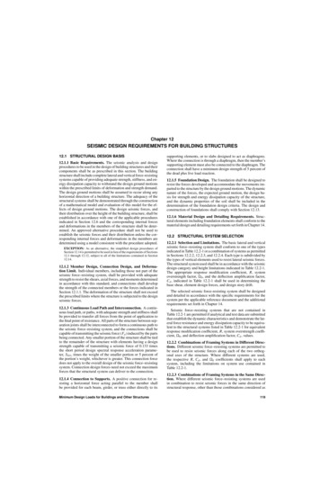
P1: JsYASCE003-12.texASCE003/SIE-v1.clsOctober 15, 2005DeMAXIMUM DIAPHRAGMDEFLECTION (MDD)SEISMIC LOADINGAVERAGE DRIFT OF VERTICAL ELEMENT(ADVE)SNote: Diaphragm is flexible if MDD 2(ADVE).FIGURE 12.3-1 FLEXIBLE DIAPHRAGMto the moment frames exceeds 35 psf (1.68 kN/m2 ). In addition, the dead load of the exterior walls tributary to themoment frame shall not exceed 20 psf (0.96 kN/m2 ).12.2.5.8 Single-Story Steel Ordinary and IntermediateMoment Frames in Structures Assigned to Seismic DesignCategory F. Single-story steel ordinary moment frames and intermediate moment frames in structures assigned to Seismic Design Category F are permitted up to a height of 65 ft (20 m)where the dead load supported by and tributary to the roof doesnot exceed 20 psf (0.96 kN/m2 ). In addition, the dead loads ofthe exterior walls tributary to the moment frame shall not exceed20 psf (0.96 kN/m2 ).12.2.5.9 Other Steel Intermediate Moment Frame Limitations in Structures Assigned to Seismic Design Category F. Inaddition to the limitations for steel intermediate moment framesin structures assigned to Seismic Design Category E as set forthin Section 12.2.5.7, steel intermediate moment frames in structures assigned to Seismic Design Category F are permitted inlight-frame construction.12.2.5.10 Shear Wall-Frame Interactive Systems. The shearstrength of the shear walls of the shear wall-frame interactivesystem shall be at least 75 percent of the design story shear ateach story. The frames of the shear wall-frame interactive systemshall be capable of resisting at least 25 percent of the design storyshear in every story.12.3 DIAPHRAGM FLEXIBILITY, CONFIGURATIONIRREGULARITIES, AND REDUNDANCY12.3.1 Diaphragm Flexibility. The structural analysis shall consider the relative stiffnesses of diaphragms and the vertical elements of the seismic force–resisting system. Unless a diaphragmcan be idealized as either flexible or rigid in accordance with Sections 12.3.1.1, 12.3.1.2, or 12.3.1.3, the structural analysis shallexplicitly include consideration of the stiffness of the diaphragm(i.e., semirigid modeling assumption).12.3.1.1 Flexible Diaphragm Condition. Diaphragms constructed of untopped steel decking or wood structural panels arepermitted to be idealized as flexible in structures in which thevertical elements are steel or composite steel and concrete bracedframes, or concrete, masonry, steel, or composite shear walls.Diaphragms of wood structural panels or untopped steel decksin one- and two-family residential buildings of light-frame construction shall also be permitted to be idealized as flexible.12.3.1.2 Rigid Diaphragm Condition. Diaphragms of concreteslabs or concrete filled metal deck with span-to-depth ratios of1243 or less in structures that have no horizontal irregularities arepermitted to be idealized as rigid.12.3.1.3 Calculated Flexible Diaphragm Condition. Diaphragms not satisfying the conditions of Sections 12.3.1.1 or12.3.1.2 are permitted to be idealized as flexible where the computed maximum in-plane deflection of the diaphragm under lateralload is more than two times the average story drift of adjoiningvertical elements of the seismic force–resisting system of the associated story under equivalent tributary lateral load as shown inFig. 12.3-1. The loadings used for this calculation shall be thoseprescribed by Section 12.8.12.3.2 Irregular and Regular Classification. Structures shallbe classified as regular or irregular based upon the criteria inthis section. Such classification shall be based on horizontal andvertical configurations.12.3.2.1 Horizontal Irregularity. Structures having one ormore of the irregularity types listed in Table 12.3-1 shall be designated as having horizontal structural irregularity. Such structuresassigned to the seismic design categories listed in Table 12.3-1shall comply with the requirements in the sections referenced inthat table.12.3.2.2 Vertical Irregularity. Structures having one or moreof the irregularity types listed in Table 12.3-2 shall be designatedas having vertical irregularity. Such structures assigned to theseismic design categories listed in Table 12.3-2 shall comply withthe requirements in the sections referenced in that table.EXCEPTIONS:1. Vertical structural irregularities of Types 1a, 1b, or 2 in Table 12.3-2do not apply where no story drift ratio under design lateral seismicforce is greater than 130 percent of the story drift ratio of the next storyabove. Torsional effects need not be considered in the calculation ofstory drifts. The story drift ratio relationship for the top two stories ofthe structure are not required to be evaluated.2. Irregularities Types 1a, 1b, and 2 of Table 12.3-2 are not required tobe considered for one-story buildings in any seismic design categoryor for two-story buildings assigned to Seismic Design Categories B, C,or D.12.3.3 Limitations and Additional Requirements for Systemswith Structural Irregularities.12.3.3.1 Prohibited Horizontal and Vertical Irregularities forSeismic Design Categories D through F. Structures assigned toSeismic Design Category E or F having horizontal irregularityType 1b of Table 12.3-1 or vertical irregularities Type 1b, 5a, or5b of Table 12.3-2 shall not be permitted. Structures assigned toSeismic Design Category D having vertical irregularity Type 5bof Table 12.3-2 shall not be permitted.ASCE 7-0517:48
P1: JsYASCE003-12.texASCE003/SIE-v1.clsOctober 15, 2005TABLE 12.3-1 HORIZONTAL STRUCTURAL IRREGULARITIESIrregularity Type and Description1a.Torsional Irregularity is defined to exist where the maximum story drift, computed including accidentaltorsion, at one end of the structure transverse to an axis is more than 1.2 times the average of the story drifts atthe two ends of the structure. Torsional irregularity requirements in the reference sections apply only tostructures in which the diaphragms are rigid or semirigid.1b.Ex
SEISMIC DESIGN REQUIREMENTS FOR BUILDING STRUCTURES 12.1 STRUCTURAL DESIGN BASIS 12.1.1 Basic Requirements. . and Building Height (ft) Limitc Seismic Design Category B C Dd Ed Fe A. BEARING WALL SYSTEMS 1. Special reinforced concrete shear walls 14.2 and 14.2.3.6 5 21/2 5 NL NL 160 160 100 2. Ordinary reinforced concrete shearFile Size: 563KBPage Count: 24