Transcription
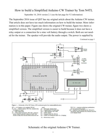
Adafruit Motor ShieldCreated by lady dLast updated on 2021-11-15 05:50:46 PM EST Adafruit IndustriesPage 1 of 50
Table of ContentsOverview5FAQ6Make It!11 Lets go!11Preparation11 Tutorials Tools1112Parts List15Solder It18Use It!34Library Install34 First Install the Arduino LibraryPower Usage Powering your DC motors, voltage and current requirements How to set up the Arduino Shield for powering motors34353536Using RC Servos38Using Stepper Motors39Using DC Motors41 DC motors are used for all sort of robotic projects.42AF DCMotor Class AF DCMotor motorname(portnum, freq) setSpeed(speed) run(cmd)AF Stepper Class AF Stepper steppername(steps, portnumber)step(steps, direction, style)setSpeed(RPMspeed)onestep(direction, stepstyle)release()Resources Motor ideas and tutorialsDownloads Schematics & Layout Firmware Adafruit Industries434345454646474848494949494949Page 2 of 50
Forums Adafruit Industries50Page 3 of 50
Adafruit IndustriesPage 4 of 50
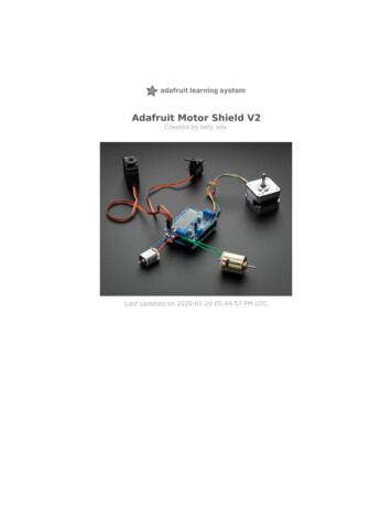
OverviewThis tutorial is for the now ancient V1 Motor shield. Chances are you have a V2,check out the tutorial 2-forarduino This tutorial is for historical reference and previous customers only!Arduino is a great starting point for electronics, and with a motor shield it can also bea nice tidy platform for robotics and mechatronics. Here is a design for a full-featuredmotor shield that will be able to power many simple to medium-complexity projects. 2 connections for 5V 'hobby' servos connected to the Arduino's high-resolutiondedicated timer - no jitter! Up to 4 bi-directional DC motors with individual 8-bit speed selection (so, about0.5% resolution) Up to 2 stepper motors (unipolar or bipolar) with single coil, double coil,interleaved or micro-stepping. 4 H-Bridges: L293D chipset provides 0.6A per bridge (1.2A peak) with thermalshutdown protection, 4.5V to 25V Pull down resistors keep motors disabled during power-up Big terminal block connectors to easily hook up wires (10-22AWG) and power Arduino reset button brought up top 2-pin terminal block to connect external power, for seperate logic/motorsupplies Tested compatible with Mega, Diecimila, & Duemilanove Full kit available for purchase from the Adafruit shop. (http://adafru.it/81) Adafruit IndustriesPage 5 of 50
Download the easy-to-use Arduino software libraries and you're ready to go! (https://adafru.it/aON)FAQThis tutorial is for the now ancient V1 Motor shield. Chances are you have a V2,check out the tutorial 2-forarduino This tutorial is for historical reference and previous customers only!How many motors can I use with this shield?You can use 2 DC servos that run on 5V and up to 4 DC motors or 2 steppermotors (or 1 stepper and up to 2 DC motors)Can I connect more motors?No, at this time it is not possible to stack the shield or otherwise connect it upeasily to control 4 steppers, for example.HELP! My motor doesnt work! - HELP! My motor doesntwork!.But the servos work FINE!Is the LED lit? The Stepper and DC motor connections wont do a single thing if theLED is not lit Adafruit IndustriesPage 6 of 50
Don't bother writing up uploading code or wiring up motors if the LED doesn't lightup, its not going to work.What is the LED for?The LED indicates the DC/Stepper motor power supply is working. If it is not lit,then the DC/Stepper motors will not run. The servo ports are 5V powered anddoes not use the DC motor supply.I'm trying to build this robot and it doesn't seem to run ona 9V battery.Please read the user manual (https://adafru.it/aOz) for information aboutappropriate power supplies.Can this shield control small 3V motors?Not really, its meant for larger, 6V motors. It does not work for 3V motors unlessyou overdrive them at 6V and then they will burn out fasterWhat is the power connector on the shield for? How do Ipower my motors?Please read the user manual (https://adafru.it/aOz) for information aboutappropriate power supplies.My Arduino freaks out when the motors are running! Is theshield broken?Motors take a lot of power, and can cause 'brownouts' that reset the Arduino. Forthat reason the shield is designed for seperate (split) supplies - one for theelectronics and one for the motor. Doing this will prevent brownouts. Please readthe user manual (https://adafru.it/aOz) for information about appropriate powersupplies.I have good solid power supplies, but the DC motorsseem to 'cut out' or 'skip'.Try soldering a ceramic or disc 0.1uF capacitor between the motor tabs (on themotor itself!) this will reduce noise that could be feeding back into the circuit(thanks macegr (https://adafru.it/clc)!) Adafruit IndustriesPage 7 of 50
What if I need more than 600mA per motor?You can subsitute SN754410's (at your risk) or piggyback solder some more L293Ddrivers on top of the existing ones. (https://adafru.it/aOz)What pins are not used on the motor shield?All 6 analog input pins are available. They can also be used as digital pins (pins #14thru 19)Digital pin 2, and 13 are not used.The following pins are in use only if the DC/Stepper noted is in use:Digital pin 11: DC Motor #1 / Stepper #1 (activation/speed control)Digital pin 3: DC Motor #2 / Stepper #1 (activation/speed control)Digital pin 5: DC Motor #3 / Stepper #2 (activation/speed control)Digital pin 6: DC Motor #4 / Stepper #2 (activation/speed control)The following pins are in use if any DC/steppers are usedDigital pin 4, 7, 8 and 12 are used to drive the DC/Stepper motors via the 74HC595serial-to-parallel latchThe following pins are used only if that particular servo is in use:Digitals pin 9: Servo #1 controlDigital pin 10: Servo #2 controlWhich pins are connected to the DC/Stepper motors?The DC/Stepper motors are NOT connected to the Arduino directly. They areconnected to the 74HC595 latch which is spoken to by the Arduino. You CANNOTtalk directly to the motors, you MUST use the motor shield library.Huh? I don't understand.You can try reading this nice overview written by Michael K (https://adafru.it/aO9)How can I connect to the unused pins?The analog pins (analog 0-5 also known as digital pins 14-19) are broken out in thebottom right corner.Pin 2 has a small breakout since its the only truly unused pin Adafruit IndustriesPage 8 of 50
The remaining pins are not broken out because they could be used by the motorshield. If you are sure that you are not using those pins then you can connect tothem by using stacking headers when assembling the kit or soldering onto the topof the header with wires, or using a "Wing shield"I get the following error trying to run the example code:"error: AFMotor.h: No such file or directory."Make sure you have installed the AFMotor libraryHow do I install the library?Read our tutorial on libraries (https://adafru.it/aYG)I have two stepper motors and I want to run themsimulaneously but the example code can only control oneand then the other?The stepper motor library step() routine does not have the ability to run bothmotors at a time. Instead, you will have to 'interleave' the calls. For example, tohave both motors step forward 100 times you must write code like this:for (i 0; i 100; i ) {motor1.step(1, FORWARD, SINGLE);motor2.step(1, FORWARD, SINGLE);}If you want more intelligent control, check out the AccelStepper library (in theDownloads section) which has some concurrent stepper motor control examplesWhat are some 'suggested motors'?Most people buy motors from surplus shops and no motor will make everyonehappyHowever, since its a popular question, I suggest buying motors from Pololu (DCServos (https://adafru.it/aOa), DC motors (https://adafru.it/aOb)) or Jameco (allsorts (https://adafru.it/aOc)!) As well as the many surplus webshops (https://adafru.it/aOd). Adafruit IndustriesPage 9 of 50
Is the motor shield compatible with the UNO R3 or MegaR3? What about the extra pins?The motor shield is compatible with the R3 UNO and MEGA. The R3s have 2 extrapins on each header. These are duplicates of other pins on the header and are notneeded by the shield.I'm using a 4WD robot platform and I can't get anything towork.The motors used in the 4WD robot platforms from Maker Shed, DF Robotics,Jameco and others have a lot of "brush noise". This feeds back into the Arduinocircuitry and causes unstable operation. This problem can be solved by soldering3 noise suppression capacitors to the motor. 1 between the motor terminals, andone from each terminal to the motor casing. Adafruit IndustriesPage 10 of 50
But my motor already has a capacitor on it and it stilldoesn't work.These motors generate a lot of brush noise and usually need the full 3-capacitortreatment for adequate suppression.Why don't you just design capacitors into the shield?They would not be effective there. The noise must be suppressed at the source orthe motor leads will act like antennae and broadcast it to the rest of the system.Make It!This tutorial is for the now ancient V1 Motor shield. Chances are you have a V2,check out the tutorial 2-forarduino This tutorial is for historical reference and previous customers only!Lets go!This is a vey easy kit to make, just go through each of these steps to build the kit1. Tools and preparation (https://adafru.it/aOv)2. Check the parts list (https://adafru.it/aOw)3. Solder it (https://adafru.it/aOx)PreparationThis tutorial is for the now ancient V1 Motor shield. Chances are you have a V2,check out the tutorial 2-forarduino This tutorial is for historical reference and previous customers only!Tutorials Learn how to solder with tons of tutorials! (https://adafru.it/aOm)(https://adafru.it/aOm) Don't forget to learn how to use your multimeter too! (https://adafru.it/aOy) Adafruit IndustriesPage 11 of 50
ToolsThere are a few tools that are required for assembly. None of these tools areincluded. If you don't have them, now would be a good time to borrow or purchasethem. They are very very handy whenever assembling/fixing/modifying electronicdevices! I provide links to buy them, but of course, you should get them where ever ismost convenient/inexpensive. Many of these parts are available in a place like RadioShack or other (higher quality) DIY electronics stores.Soldering ironAny entry level 'all-in-one' soldering ironthat you might find at your local hardwarestore should work. As with most things inlife, you get what you pay for.Upgrading to a higher end soldering ironsetup, like the Hakko FX-888 that westock in our store (http://adafru.it/180),will make soldering fun and easy.Do not use a "ColdHeat" soldering iron!They are not suitable for delicateelectronics work and can damage the kit(see here (https://adafru.it/aOo)).Click here to buy our entrylevel adjustable 30W 110V solderingiron. (http://adafru.it/180)Click here to upgrade to a GenuineHakko FX-888 adjustable temperaturesoldering iron. (http://adafru.it/303) Adafruit IndustriesPage 12 of 50
SolderYou will want rosin core, 60/40 solder.Good solder is a good thing. Bad solderleads to bridging and cold solder jointswhich can be tough to find.Click here to buy a spool of leadedsolder (recommended forbeginners). (http://adafru.it/145)Click here to buy a spool of lead-freesolder. (http://adafru.it/734) Adafruit IndustriesPage 13 of 50
MultimeterYou will need a good quality basicmultimeter that can measure voltage andcontinuity.Click here to buy a basicmultimeter. (http://adafru.it/71)Click here to buy a top of the linemultimeter. (http://adafru.it/308)Click here to buy a pocketmultimeter. (http://adafru.it/850)Flush Diagonal CuttersYou will need flush diagonal cutters totrim the wires and leads off ofcomponents once you have solderedthem in place.Click here to buy our favoritecutters. (http://adafru.it/152) Adafruit IndustriesPage 14 of 50
Solder SuckerStrangely enough, that's the technicalterm for this desoldering vacuum tool.Useful in cleaning up mistakes, everyelectrical engineer has one of these ontheir desk.Click here to buy a one. (http://adafru.it/148)Helping Third Hand With MagnifierNot absolutely necessary but will makethings go much much faster, and it willmake soldering much easier.Pick one up here. (http://adafru.it/291)Parts ListThis tutorial is for the now ancient V1 Motor shield. Chances are you have a V2,check out the tutorial 2-forarduino This tutorial is for historical reference and previous customers only!Image Adafruit IndustriesNameDescriptionDistributorQtyPCBPrinted CircuitBoardAdafruit1Page 15 of 50
L293DDual H-bridgeIC1,IC2IC3IC1'andIC2'LED1R1 Adafruit Industries*See note onL293Dusage page forreplacing withSN75441074HC595NSerial toparallel outputlatch274HC595N116 pin sockets(OPTIONAL!)GenericThese areincluded in kitsas of July 20103mm LED, anycolorMotor powerindicator23mm LED1.5K resistor for 1/4W 5%LED1resistor11Page 16 of 50
Adafruit IndustriesR210K pulldownresistorBrown, Black,Orange, Gold1/4W 5%resistor1RN110-pin 2,C4, C60.1uF ceramiccapacitorGeneric3C1, C3,C5100uF / 6Vcapacitor (orbigger)100uF/6Vcap3C7, C847uF / 25Vcapacitor (orbigger)47uF/25Vcap2Page 17 of 50
X15-position3.5mm terminalblock3.5mm(Or a 3-position terminals2and a 2position)X22-position3.5mm3.5mm terminalterminalsblock1RESET6mm tactileswitch6mm tactswitch1PWRJumper/shunt0.1" jumper136 pin maleheader (1x36)Generic1Solder ItThis tutorial is for the now ancient V1 Motor shield. Chances are you have a V2,check out the tutorial 2-forarduino This tutorial is for historical reference and previous customers only! Adafruit IndustriesPage 18 of 50
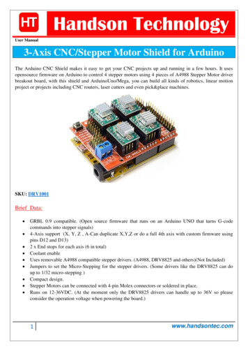
First, check that you have all the parts!Look over the parts list here (https://adafru.it/aOw) and shown on the left.Also check to make sure you have thenecessary tools for assembly. (https://adafru.it/aOv)Place the motor shield PCB in a vise orother circuit-board holder and turn onyour soldering iron to 700 degrees.The first parts to go in are the tworesistors, R1 (Brown Green Red Gold)and R2 (Brown Black Orange Gold). Bendthe resistors so that they look likestaples, as seen in this photo.Next, slip the resistors into the PCB asshown, so that they sit flat against thecircuit board. Bend the wire legs out a bitso that when the board is flipped overResistors are not polarized, that meansyou can put them in "either way" andthey'll work just fine. Adafruit IndustriesPage 19 of 50
Using your soldering iron tip, heat theresistor wire lead and the metal ring (pad)at the same time, after a few seconds,poke a little solder in so that it melts intoa nice cone. Remove the solder and thenremove the soldering iron. Do this for all4 wires.Check your work, you should have cleansolder joints. Adafruit IndustriesPage 20 of 50
Clip the long leads, just above the solderjoint using diagonal cutters.Next place the three yellow ceramiccapacitors C4, C2 andC6. Ceramiccapacitors are not polarized so you canput them in "either way" and they workfine.Bend the leads out just like you did withthe resistors. Adafruit IndustriesPage 21 of 50
Solder all 6 wires, then clip them as youdid with the resistors.Next is the 6mm tactile switchRESET andthe resistor networkRN1. The tact switchis used to reset the Arduino since its notpossible to reach the reset button oncethe motor shield is on.The resistor network is used topulldown the pins on the motor driver chipsso that they don't power up the motorsbefore the Arduino sketch tells them to.The tactile switch can go in 'either way'.The resistor network, however, must goin a certain way. Make sure the end witha dot is posititioned so it is at the sameend as the X in the silkscreened image ofthe resistor network. (See picture on left). Adafruit IndustriesPage 22 of 50
Flip the board over and solder in theresistor network and switch. You won'tneed to clip the leads as they are quiteshort aleady.Next are the three integrated circuits(ICs) IC1, IC2 and IC3. When ICs comefrom the factory, the legs are angled outsomewhat which makes it difficult toinsert them into the PCB. Prepare themfor soldering by gently bending the legsagainst a flat tabletop so that they areperfectly straight.The latest kits from Adafruit come with 216-pin sockets for the L293D motordrivers. They are OPTIONAL and notnecessary for operation.If you are not experienced with drivingmotors ( your likelyhood of wiring up amis-specified motor is high) you shouldinstall these so if the L293Ds aredestroyed you can easily replace themIf you are experienced with drivingmotors, you may want to skip the socketsas the decrease the chips' heat-sinkingabilities. Adafruit IndustriesPage 23 of 50
ICs must be placed in the correctorientation to work properly. To help withplacement, each chip has a U notch atthe top of the chip. On the circuit boardthere is a printed out image of the chipoutline and one end has a U notch. Makesure the chip notch is on the same endas the image notch. In this PCB, all arefacing the same way.Gently insert the three chips. Check tomake sure none of the legs got bent orbroken.The 74HC595 goes in the middle, andthe two L293Ds go on either side. Adafruit IndustriesPage 24 of 50
Solder each pin of the chips.The four 'middle' pins of the L293Dmotor driver chips are tied to a large heatsink and thus may end up getting'bridged' with solder as shown in thesecond image. Adafruit IndustriesPage 25 of 50
Next are the three 100uF electrolyticcapacitors C1, C3and C5. Electrolyticcapacitors are polarized and must beplaced in the correct orientation or theycould pop! The long leg of the capacitoris the positive ( ) leg and goes into thehole marked with a . The close-upimages shown here indicate with hole isthe one.Capacitors are not color-coded. Thebody color can vary from blue to violet togreen to black sobe sure to read thevalue on the side, don't depend on thecolor!After double-checking their polarity,solder and clip the three capacitors. Adafruit IndustriesPage 26 of 50
Place the two 47uF remaining electrolyticcapacitors, C7 andC8These are also polarized so make surethe long lead is inserted into the hole inthe silkscreened image.Capacitors are not color-coded. Thebody color can vary from blue to violet togreen to black sobe sure to read thevalue on the side, don't depend on thecolor! Adafruit IndustriesPage 27 of 50
Solder and clip the two capacitors.Next is the 3mm LED used to indicatemotor power. LEDs are polarized, just likecapacitors, and the long lead is thepositive ( ) lead.Make sure the LED is placed correctlyotherwise it wont work! Adafruit IndustriesPage 28 of 50
Solder and clip the LED leads. Adafruit IndustriesPage 29 of 50
Next its time to make the headers for thejumper, servos and arduino.We use one stick of 36-pin 'breakaway'header, and break it apart to makesmaller strips. You can use diagonalcutters or pliers to snap off the pieces.Break the 36-pin header into 2 8-pin, 2 6pin, 2 3-pin and 1 2-pin headers.If you have an NG arduino, you may want1 6-pin header and 1 4-pin header insteadof 2 6-pin headers. Adafruit IndustriesPage 30 of 50
The 2 3-pin pieces go in the servoconnections in the top left corner. The 2pin piece goes in the PWR jumper in thebottom center.Also, place the 3 large screw terminalsfor the motor and external motor-powerwires. If you received only 2 and 3position terminal blocks, slide themtogether so that you have 2 5-positionterminals and 1 2-position terminal. Adafruit IndustriesPage 31 of 50
Solder in the 3 pieces of header and thethree terminal blocks. Adafruit IndustriesPage 32 of 50
Next, place the 8-pin and 6-pin headersinto the Arduino board. This will makesure that the headers are perfectly linedup. Make sure the Arduino is not pluggedin or powered!Place the motor shield on top of theArduino, making sure that all the headerlines up.Solder in each pin of the header. Adafruit IndustriesPage 33 of 50
You're done!Now go read the user manual. (https://adafru.it/aOz)Use It!This tutorial is for the now ancient V1 Motor shield. Chances are you have a V2,check out the tutorial 2-forarduino This tutorial is for historical reference and previous customers only!The Adafruit Motor Shield kit is a great motor controller for Arduino, but it does a littlecare to make sure it's used correctly. Please read through all the User manualsections at left, especially the section about library installation and powerrequirements!Library InstallThis tutorial is for the now ancient V1 Motor shield. Chances are you have a V2,check out the tutorial 2-forarduino This tutorial is for historical reference and previous customers only!First Install the Arduino LibraryBefore you can use the Motor shield, you must install the AF Motor Arduino library this will instruct the Arduino how to talk to the Adafruit Motor shield, and it isn'toptional!Open up the Arduino library manager: Adafruit IndustriesPage 34 of 50
Search for Adafruit Motor library and install it. Make sure it is the library for the V1motor shield.We also have a great tutorial on Arduino library installation duino-libraries-install-use (https://adafru.it/aYM)Power UsageThis tutorial is for the now ancient V1 Motor shield. Chances are you have a V2,check out the tutorial 2-forarduino This tutorial is for historical reference and previous customers only!Powering your DC motors, voltage andcurrent requirementsMotors need a lot of energy, especially cheap motors since they're less efficient. Thefirst important thing to figure out what voltage the motor is going to use. If you'relucky your motor came with some sort of specifications. Some small hobby motors areonly intended to run at 1.5V, but its just as common to have 6-12V motors. The motorcontrollers on this shield are designed to run from 4.5V to 25V.MOST 1.5-3V MOTORS WILL NOT WORKCurrent requirements: The second thing to figure out is how much current your motorwill need. The motor driver chips that come with the kit are designed to provide up to Adafruit IndustriesPage 35 of 50
600 mA per motor, with 1.2A peak current. Note that once you head towards 1A you'llprobably want to put a heatsink on the motor driver, otherwise you will get thermalfailure, possibly burning out the chip.On using the SN754410: Some people use the SN754410 (https://adafru.it/aOB) motordriver chip because it is pin-compatible, has output diodes and can provide 1A permotor, 2A peak. After careful reading of the datasheet and discussion with TI techsupport and power engineers it appears that the output diodes were designed forESD protection only and that using them as kickback-protection is a hack and notguaranteed for performance. For that reason the kit does not come with theSN754410 and instead uses the L293D with integrated kickback-protection diodes. Ifyou're willing to risk it, and need the extra currrent, feel free to buy SN754410's andreplace the provided chips.Need more power? Buy another set of L293D drivers and solder them right on top ofthe ones on the board (piggyback) (https://adafru.it/aOC). Voila, double the currentcapability! You can solder 2 more chips on top before it probably isnt going to get youmuch benefitYou can't run motors off of a 9V battery so don't even waste your time/batteries! Usea big Lead Acid or NiMH battery pack. Its also very much suggested that you set uptwo power supplies (split supply) one for the Arduino and one for the motors. 99% of'weird motor problems' are due to noise on the power line from sharing powersupplies and/or not having a powerful enough supply!How to set up the Arduino Shield forpowering motorsServos are powered off of the same regulated 5V that the Arduino uses. This is OK forthe small hobby servos suggested. If you want something beefier, cut the trace goingto on the servo connectors and wire up your own 5-6V supply!The DC motors are powered off of a 'high voltage supply' and NOT the regulated5V. Don't connect the motor power supply to the 5V line. This is a very very very badidea unless you are sure you know what you're doing! Adafruit IndustriesPage 36 of 50
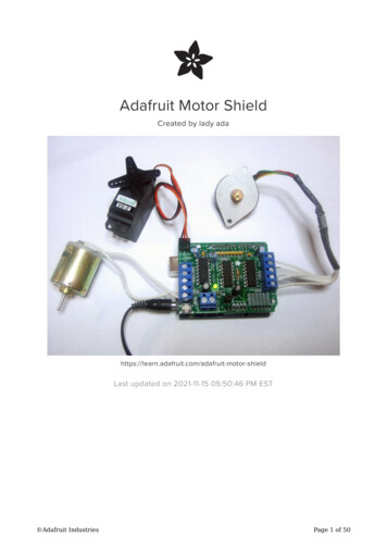
There are two places you can get your motor 'high voltage supply' from. One is theDC jack on the Arduino board and the other is the 2-terminal block on the shield thatis labeled EXT PWR. The DC Jack on the Arduino has a protection diode so you won'tbe able to mess things up too bad if you plug in the wrong kind of power. Howeverthe EXT PWR terminals on the shield do not have a protection diode (for a fairly goodreason). Be utterly careful not to plug it in backwards or you will destroy the motorshield and/or your Arduino!Here's how it works:If you would like to have a single DC power supply for the Arduino and motors, simplyplug it into the DC jack on the Arduino or the 2-pin PWR EXT block on the shield.Place the power jumper on the motor shield.If you have a Diecimila Arduino, set the Arduino power source jumper to EXT.Note that you may have problems with Arduino resets if the battery supply is not ableto provide constant power, and it is not a suggested way of powering your motorprojectIf you would like to have the Arduino powered off of USB and the motors powered offof a DC power supply, plug in the USB cable. Then connect the motor supply to thePWR EXT block on the shield. Do not place the jumper on the shield. This is asuggested method of powering your motor project(If you have a Diecimila Arduino, don't forget to set the Arduino power jumper to USB.If you have a Diecimila, you can alternately do the following: plug the DC powersupply into the Arduino, and place the jumper on the motor shield.)If you would like to have 2 seperate DC power supplies for the Arduino and motors.Plug in the supply for the Arduino into the DC jack, and connect the motor supply to Adafruit IndustriesPage 37 of 50
the PWR EXT block. Make sure the jumper is removed from the motor shield.If you have a Diecimila Arduino, set the Arduino jumper to EXT. This is a suggestedmethod of powering your motor projectEither way, if you want to use the DC motor/Stepper system the motor shield LEDshould be lit indicating good motor powerUsing RC ServosThis tutorial is for the now ancient V1 Motor shield. Chances are you have a V2,check out the tutorial 2-forarduino This tutorial is for historical reference and previous customers only!Hobby servos are the easiest way to get going with motor control. They have a 3-pin0.1" female header connection with 5V, ground and signal inputs. The motor shieldsimply brings out the 16bit PWM output lines to two 3-pin headers so that its easy toplug in and go. They can take a lot of power so a 9V battery wont last more than afew minutes!The nice thing about using the onboard PWM is that its very precise and goes aboutits business in the background. You can use the built in Servo libraryUsing the servos is easy, please read the official Arduino documentation for how touse them and see the example Servo sketches in the IDE (https://adafru.it/aOD). Adafruit IndustriesPage 38 of 50
Power for the Servos comes from the Arduino's on-board 5V regulator, powereddirectly from the USB or DC power jack on the Arduino. If you need an externalsupply, cut the trace right below the servo pins (on v1.2 boards) and connect a 5V or6V DC supply directly. Using an external supply is for advanced users as you canaccidentally destroy the servos by connecting a power supply incorrectly!When using the external supply header for servos, take care that the bottom ofthe header pins do not contact the metal USB port housing on the Arduino. Apiece of electrical tape on the housing will protect against shorts.Using Stepper MotorsThis tutorial is for the now ancient V1 Motor shield. Chances are you have a V2,check out the tutorial 2-forarduino This tutorial is for historical reference and previous customers only!Stepper motors are great for (semi-)precise control, perfect for many robot and CNCprojects. This motor shield supports up to 2 stepper motors. The library worksidentically for bi-polar and uni-polar motorsFor unipolar motors: to connect up the stepper, first figure out which pins connectedto which coil, and which pins are the center taps. If its a 5-wire motor then there willbe 1 that is the center tap for both coils. Theres plenty of tutorials online on how toreverse engineer the coils pinout. (https://adafru.it/aOO) The center taps should bothbe connected together to the GND terminal on the motor shield output block. then Adafruit IndustriesPage 39 of 50
coil 1 should connect to one motor port (say M1 or M3) and coil 2 should connect tothe other motor port (M2 or M4).For bipolar motors: its just like unipolar motors except theres no 5th wire to connectto ground. The code is exactly the same.Running a stepper is a little more intricate than running a DC motor but its still veryeasy1. Make sure you #include AFMotor.h 2. Create the stepper motor object with AF Stepper(steps, stepper#) to setup themotor H-bridge and latches. Steps indicates how many steps per revolution themotor has. a 7.5degree/step motor has 360/7.5 48 steps. Stepper# is whichport it is connected to. If you're using M1 and M2, its port 1. If you're using M3and M4 it's port 23. Set the speed of the motor using setSpeed(rpm) where rpm is how manyrevolutions per minute you want the stepper to turn.4. Then every time you want the moto
Nov 15, 2021 · Arduino is a great starting point for electronics, and with a motor shield it can also be a nice tidy platform for robotics and mechatronics. Here is a design for a full-featured motor shield that will be able to power many simple to medium-complexity projects. 2 connections for 5V 'hobby' servos co