Transcription
Solar Hydroponics Monitoring VehiclesFinal Research Project ReportSAC Undergraduate Research ProjectDesign and Drive Team:Tepher WardJuli WilliamsMichelle MataSubmitted: August 19, 2016
SURP – Hydroponics Monitor VehiclesTABLE OF CONTENTSAbstract . 3Participants and Acknowledgements . 4Introduction . 5Materials and Methods. 6V1 – Tetrix Vehicle . 7V2 – Hybrid Vehicle . 10Results and Discussion . 13V1 – Tetrix Vehicle . 13V2 – Hybrid Vehicle . 14Conclusions . 17References . 19Appendicies . 21Appendix A – Parts and Materials Lists by Vehicle . 21Appendix B – Image Views of Vehicles . 24Appendix C – V2 Speed Tests . 26Page 2
SURP – Hydroponics Monitor VehiclesABSTRACTThe ReEnergize Solar Hydroponics project at the SAC Eco Centro needs tools to enable monitoring ofgrowing plants while minimizing entry and exit from the outside (Lewis). A mobile robot that can staywithin the container while allowing remote control and transmission of visual and sensor data wouldhave substantial benefit. Two remote monitoring vehicle prototypes were built to test the feasibility ofan affordable, expandable and rugged mobile robot to be used within a hydroponic shipping container.The first vehicle was built from Tetrix parts and uses an Arduino microcontroller. The second vehicle,built from PVC and other common materials, is controlled by a Raspberry Pi single board computer.Both vehicles can be controlled remotely and stream video from an on-board camera, and both are largeenough to accommodate additional equipment to extend functionality. The first vehicle is more rugged,but the second vehicle offers more flexibility at half the cost of the first. The project has met its primaryobjectives of having remote control drivability and camera visibility via WiFi. Future enhancementsinclude the line sensors for the vehicles to follow pre-programmed paths for sensor readings and theswivel-mount for the camera to view objects from left to right or up and down without repositioning thevehicle. Adding a camera hoisting mechanism to view higher plant racks will require retesting thevehicles’ balance and weight distribution to ensure consistent traction. As sensor equipment is added,the WiFi will need to transmit the additional data readings. The final enhancement recommended is tomake all systems moisture-proof.Page 3
SURP – Hydroponics Monitor VehiclesPARTICIPANTS AND ACKNOWLEDGEMENTSTeam ParticipantsStephanie (Tepher) Ward – Team Leader; V1 & V2 Design & ConstructionJuli Williams – V2 Lead, V2 programmerMichelle Mata – V1 Lead, V1 programmerTeam Advisors and SupportersMr. Steven Lewis – Director of Eco Centro, Project AdvisorMr. Klaus Bartels – Adjunct Faculty, Physics, Engineering, and Architecture Department, Project AdvisorMr. Ben Uresti – Academic Lab Technician for the MESA Center, Technical AdvisorMs. Bly Korseau – Engineering Administrative AssistantMs. Barbara Knotts – Adelante Tejas Project Grant DirectorMs. Patty Medina – Exitos Grant DirectorMs. Dee Dixon – MESA Center CoordinatorMs. Sylvia San Miguel – Administrative AssistantMs. Susan Paddock – LSAMP/CIMA Grant Co-PIMs. Susan Espinoza – Director of College Grants and DevelopmentDr. Robert Vela – SAC PresidentSponsorsExitos grant (Award No. 031S140099) – Grantor and SupporterAdelante Tejas (Award No. PO31C110039) – Grantor and SupporterSan Antonio College – Contributor and SupporterPage 4
SURP – Hydroponics Monitor VehiclesINTRODUCTIONSan Antonio College works with Texas State University through the ReEnergize program, which aimsto research renewable energy alternatives and to share green technology solutions (ReEnergize Overview). San Antonio College’s Eco Centro is the home for one of the ReEnergize projects focused ondeveloping a low-cost, solar-powered hydroponic shipping container that could grow and supply foodfor local food deserts, global climate-challenged areas, or urban areas where food supplies are limited.In working with the ReEnergize Solar Hydroponics team, they discovered that the hydroponicsshipping container at Eco Centro should only be accessed on a minimal basis to reduce exposure topests and maintain optimal air, light, and water conditions for growing plants (Lewis). As costcontainment and long-term adaptability are essential for the hydroponic shipping container program,these concerns were incorporated into the goals of this project. Additionally, since the hydroponicsteams would have limited access to the shipping container for on-going monitoring and periodicsurveillance, the solution needed to be controlled remotely and to be programmable for scheduledsensor reading in various locations in the shipping container. While the shipping container will have aventilation system, the atmospheric conditions will range from 70 - 90 F and from 60% - 85% humidity.Based on the climatic extremes of the environment, the vehicle needs to be corrosion resistant inthe humid environment, energy efficient to minimize charging and down time, provide a platform forattaching and running various sensor equipment and monitors, and provide wireless video capability forvisual checks. The base of the vehicle needs to be large enough to accommodate future enhancementsthat would include a hoisting camera mechanism to view higher plant racks or to raise interchangeableattachments for harvesting or other functions. These enhancements must accommodate reaching up to8 ft., which is the interior height of the shipping container.After assessing the requirements, it was determined that a remote-controlled monitoring vehiclenot only met the needs of the ReEnergize Solar Hydroponics team but also addressed the environmentalconstraints and challenges. While there were robotic kits available, the concern was that they wouldPage 5
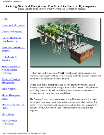
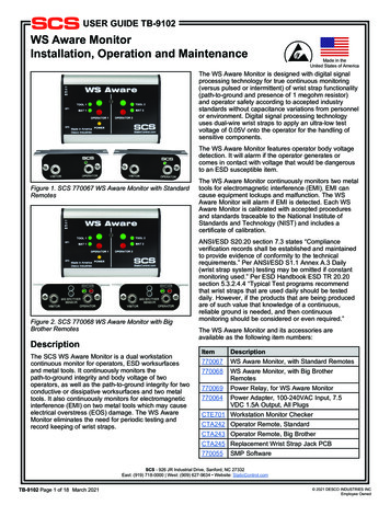
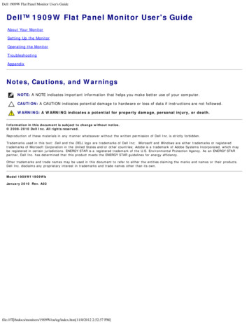
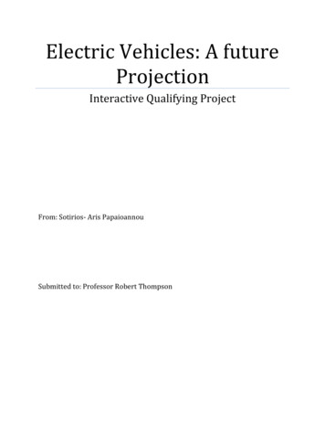
SURP – Hydroponics Monitor Vehiclesnot meet the program requirements of being cost efficient and adaptable. The Hydroponics MonitoringVehicles team set out to compare two vehicles to determine which would be better suited to meet allneeds, including end-user, environmental, and program requirements.Given time constraints and very limited team expertise in robotics, some features were deferred asnot key in determining the viability of the goals of the project. These included the elimination of linesensors for the vehicles to follow pre-programmed paths for sensor readings, and the elimination ofswivel-mounted cameras for viewing objects from left to right or up and down without repositioning thevehicle.MATERIALS AND METHODSTwo vehicles with similar functionality were designed and constructed to move forwards andbackwards as well as to turn on command. The Tetrix vehicle (V1) was made with Tetrix parts with anArduino controller (Figure 1). The hybrid vehicle (V2) was made of PVC and other off-the-shelfFigure 1: Tetrix Vehicle Design for V1Figure 2: Hybrid Vehicle Design for V2components available at hardware stores (Figure 2) and is controlled by a Raspberry Pi single boardcomputer. The centers of both vehicles remained open for the addition of sensors or othercomponents. Since the PVC pipe could be cut to any size, V2 was designed a bit larger to allow forPage 6
SURP – Hydroponics Monitor Vehiclesbetter balance for a future enhancement arm that would extend to the full height in the shippingcontainer of 8 feet (i.e., a camera hoisting or harvesting mechanism harvesting).The total cost to build the two vehicles was 1,298.64. Some of these costs were deferred as SanAntonio College provided two existing Tetrix Prime Kits at no cost as an alternative to the Tetrix UrbanChallenge Set. Total cost of parts and materials for V1 was 879.17 (Appendix A, Table A1), and for V2was 419.47 (Appendix A, Table A2).V1 – Tetrix VehicleConstruction (Appendix B, Images B1 – B3)The frame of the main body of V1 was constructed in a square using 288 mm beams and extendedfrom the center of the front to mount the camera. A plastic container was attached at the back tohouse the controllers and future sensors. The total length is 22.5 in. from front to back. Wheels extendout on the sides for a total width of 14 in. The height including the plastic container was 8.25 in. Thecamera was attached on a fixed mount 7 in. from the floor, which provided enough visible range to viewthe floor at approximately 12 in. in front of the vehicle.The motors were connected to the rear wheels with the battery pack for the motors in the center todistribute weight evenly. The weight of V1 including its components was 6 lbs. 15.2 oz. The 9V batteryfor the camera was secured to the frame by electrical tape.ElectronicsV1 uses an Arduino UNO microcontroller, an Arduino WiFi Shield 101 that creates an interface tocontrol theArduino UNO, a Pololu motor shield that has the capability to control two 12V motors, and anattachable wireless camera that has built-in IR LEDs for night vision.The Arduino UNO is a board that includes an ATmega328P microcontroller with a USB connection, apower jack, an ICSP header, a reset button, and a 16MHz quartz crystal. The Arduino UNO contains pinswhich are attached to the microcontroller which include 14 digital input/output pins for which 6 ofPage 7
SURP – Hydroponics Monitor Vehiclesthose can be used as a pulse-width modulation (PWM) pins, and 6 analog inputs. The Arduino UNO is asmall board of 68.6mm in length, 53.4mm in width and only weighs 25g. Technical specs of the ArduinoUNO include a 5V operating voltage, 7-12V recommended input voltage, 6-20V input voltage limit, 20mADC current per I/O pin, 50mA DC current for 3.3V pin, 2KB SRAM, 1KB EEPROM, a Clock Speed of 16MHzand a Flash Memory of 32KB which is stored in the microcontroller and of which 0.5KB is used by thebootloader (Arduino - Overview).The WiFi Shield 101 allows the Arduino UNO board to connect to a local network using IEEE 802.11wireless specifications. The shield is mounted on top of the Arduino UNO and contains an AMTELSmartConnect WINC1500 module that is a network controller capable of TCP and UDP protocols,features a hardware encryption/decryption security protocol included in the ATECC508ACryptoAuthentication chip, and includes its own downloadable library of the Arduino software. Theshield uses digital pins 5, 7, and 10. Pin 5 is used as a reset pin between the shield and Arduino, pin 7 isused as a handshake between the shield and Arduino, and pin 10 is used as an SPI to the Arduino(Arduino WiFi Shield 101).The Pololu Motor Shield included a MC33926 Motor Driver that can control up to two motors. Themotor shield was stacked on top of the WiFi Shield 101 and was separately powered from the ArduinoUNO and WiFi shield. The motor shield has a 5V minimum operating voltage, 28V maximum operatingvoltage, 3A of continuous output current per motor, 0.525 V/A current sense, 20kHz of maximum PWMfrequency, 2.5V of minimum logic voltage, 5.5V maximum logic voltage and includes reverse voltageprotection included in the MOSFET. The shield uses many pins which include digital pins 4, 7, 8, 9, 10,12, and analog pins A0 and A1. Pins 7-10 are used to control the motor’s power and speed while pin 4 isthe "if fault" command that stops the motors if a fault occurs and pin 12 disables motor output inputswhen low. Below is the truth table for the Motor shield (Table 1).Page 8
SURP – Hydroponics Monitor keHLXCoastLXXTable 1: Logic Controls for Arduino Motor Shield ProgrammingMxAMxBNotSFHLLZLHLZHHHLThe wireless camera used on V1 is the SecurityMan CUcam1 that features colored video and audio,a night vision range of 23 ft., video transmission up to 330 ft. from the receiver, and a 3.3 mm fish eyelens. It is weatherproof so it can easily be used indoors or outdoors. The website indicates it is a WiFiinterference-free camera indicating that the device will not interfere with other wireless devices(SecurityMan).ProgrammingThe Arduino software was installed and run using Windows 10 OS. The Arduino software can befound on the official Arduino site and many downloadable libraries are within the software (ArduinoSoftware). For this project it was necessary to download the WiFi Shield 101 library and the PololuMotor Shield library, which can only be obtained in the motor shield's GitHub page (Pololu / DualMC33926 Motor Shield).After mounting the WiFi shield on the Arduino, the first programming done for the project was toconnect it to a local network. The WiFi shield library contained an example of connecting the shield tothe network and in using this it was successfully connected. The WiFi shield library also contained anexample to control an LED over a web server which was also a success. The Pololu motor shield wasinitially tested directly mounted to an Arduino without the WiFi Shield 101, and it ran successfully. ThePololu motor shield had only one sample code called "DEMO" that moved both motor channels forwardand in reverse. The motor shield was then tested mounted on the WiFi shield, but then it only ran onemotor successfully with the WiFi Shield due to a pin conflict.Page 9
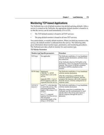
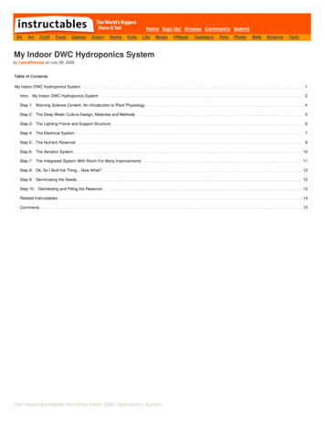
SURP – Hydroponics Monitor VehiclesTo simulate a remote environment, we attached a phone charger to provide battery power to theArduino as opposed to a direct connection of power through a PC. The Arduino powered up andexecuted the code successfully using the phone charger.V2 – Hybrid VehicleConstruction (Appendix B, Images B4 – B6)V2’s frame was constructed from a 10 ft., 0.75 in. Schedule 40 PVC pipe. Four pieces were cut to 9in. for the sides and three pieces were cut to 12 in. for the cross beams. The four 9 in. pieces make upthe side beams and were attached between ¾-inch 90-degree fittings at the ends and to a ¾-inch Teefitting at the center. The side beams were then attached with the 12 in. PVC pipes to complete theframe (Figure 2). The total length was 26.25 in. with a width of 17.5 in. and height of 8 in. to the top ofthe closed flip-top box.There are two motor-driven wheels in the rear of the vehicle held by a #2 conduit hanger with a bolttightened to prevent the motor from slipping. The top of the conduit hanger is mounted to the chassisby a 1.25 in. hose repair clamp. For the wheels without motors, thread spools of a similar size to themotors were used with the wheel axle run through the center spool keeping the vehicle balanced fromfront to back.The battery pack was placed at the rear to add weight for keeping the tires in contact with the floor.Plastic hanger straps were wound around theback frame and attached by 5 in. zip ties (Figure3). Then, a 1.5 in. by 9 in. steel plate was affixedto the lower strap with the upper strap used tocompartmentalize the battery pack. Standoffswere used to add stability between the strapsand steel plate. The weight of V2 including all itscomponents was 7 lbs. 2.7 oz.Figure 3: V2 battery holderPage 10
SURP – Hydroponics Monitor VehiclesElectronicsVehicle 2 uses a Raspberry Pi 3 single board computer, a Pololu dual motor driver add-on boardcontrolling two 12V DC motors for movement, and a Pi NoIR(no infrared) camera module providing a video feed.The Raspberry Pi 3 (RPi) features a Broadcom BCM2837 system-on-chip, combining a quad-core 64bit ARM Cortex processor at 1.2GHz clock speed, 1GB RAM, and 400MHz VideoCore IV GPU. The boardalso includes a microSD slot, built-in Bluetooth 4.0 and 802.11n WiFi connectivity, 4 USB ports, 10/100Ethernet port, HDMI connector and 3.5mm audio/video jack. Its small size, low cost, 40-pin generalpurpose input/output (GPIO) header, and large user community contributing code, project ideas, andcompatible hardware, make it ideal for inexpensive robotics projects with plenty of expansionopportunities. It is powered by a standard 5V micro USB supply, such as a cellphone charger, with atotal current draw typically under 1A (Raspberry Pi FAQs).The Pololu expansion board is capable of driving two DC motors between 5-28V and providing up to3A continuous, 5A peak current per channel, with current limiting and over-temperature protection. Ininitial testing, the 12V Tetrix DC motors each drew up to 0.15A under no load, 0.38A with a light tomoderate load, and 3.9A to start the motor. The board is plugged into the pins directly on top of theRPi, held securely with screws, and includes terminal blocks for connecting the motors and separatepower supply.The connection between the motor driver board and the RPi uses 8 GPIO pins, with each motorhaving a status flag output, enable pin (EN), direction pin (DIR), and speed input using pulse-widthmodulation (PWM). For basic operation, EN must be set to High to turn the motor on while polarity,which controls the direction the shaft turns, is set by DIR. Setting this pin to High will enablecounterclockwise rotation, while Low switches the direction to clockwise rotation (Table 2).Page 11
SURP – Hydroponics Monitor VehiclesDirectionM1EN:pin 22M1DIR:pin 24M2EN:pin 23M2DIR:pin 25ForwardHighHighHighLowM1 counterclockwise, M2 clockwiseReverseHighLowHighHighM1 clockwise, M2 counterclockwiseLeftHighLowHighLowM1 and M2 counterclockwiseRightHighHighHighHighM1 and M2 clockwiseStopTable 2: DC Motor controlsStateSpeed, PWM set to zeroThe Pi NoIR camera module uses a Sony IMX219 8M sensor and lacks an infrared filter, making itsuitable for measuring plant health when used with a blue filter (What's That Blue Thing). It connects tothe RPi through a camera serial interface (CSI) port, providing a direct connection to the GPU, andprovides video at resolutions of 1080p30, 720p60 and 640x480p90, or stills up to 3280x2464.ProgrammingThe OS used is the March 2016 release of MINIBIAN, a minimal implementation of Raspbian"Jessie" which fits on a 2GB SD card along with a selection of applications required for web-basedcontrols and streaming video. Raspbian is an operating system tailored for Raspberry Pi and derivedfrom the Debian Linux operating system.The RPi uses Apache2, a Linux-based web server software, with the mod wsgi plugin to serve anHTML file that includes a video stream from the NoIR camera with buttons to control the direction ofmovement and a text input field for setting the movement time in seconds. The webpage can beaccessed by a computer on the same local area network by opening a browser and pointing it to thestatic address given for the RPi.Video streaming is managed by Userspace Video4Linux (UV4L), which provides a web-basedstreaming server that can be accessed through port 8080 at the RPi's static address (e.g.,172.16.8.1:8080) and allows direct access to the configuration file for the video feed with appropriatecredentials. The live stream can be viewed by selecting MJPEG/Stills stream.Page 12
SURP – Hydroponics Monitor VehiclesVehicle movement uses python scripts adapted from a tutorial with code provided on the Linux User& Developer Magazine website by Liam Fraser. The basis of this code is open-source under the Apache2license, including the Bootstrap web framework which integrates a plugin allowing user interactionwithout disturbing the video feed. The scripts used to manipulate the GPIO pins associated with themotors work by setting up a Python Remote Objects (Pyro) server that allows remote access. The"movement server" script defines the GPIO pins to be used, the functions called to manipulate them,and enables the Pyro server to wait for these commands. The application script takes the argumentspassed to it from the web page and calls the assigned function to execute the command.RESULTS AND DISCUSSIONV1 – Tetrix VehicleConstructionThe design was intended to provide adaptability for the addition of future sensors along with anextended camera hoisting mechanism in the center while still remaining balanced. No holes were addedto the controller container, so wires were draped over the edge with electrical tape as an anchor. Whilethe design was original, its simplicity in structure resulted in no changes to the initial build design.ElectronicsThe initial design had included the use of Pitsco’s Tetrix PRIME Arduino Hardware Kit, whichincluded an Arduino UNO and Tetrix Motor shield at a cost of 160. This shield could only support servomotors, which are not powerful enough for moving vehicles. The final version used the Pololu motorshield, which did overcome the limitations and only cost 29.95.ProgrammingFollowing the successful programming controls for the motor shield, the WiFi shield was thenadded. A problem was encountered when the motor shield and WiFi shield were both mounted on theArduino. Both shields were interrupting the program to work properly because they used some similarpins. Adding shields on top of shields seems to be a very common problem in the Arduino community.Page 13
SURP – Hydroponics Monitor VehiclesWith the current problem there were different options to proceed with the project. One was torearrange the mapping of the motor shield pins to not make an interference; but, it would also not allowthe use of the motor shield library. Another option was to only power one motor, meaning the designof V1 would need to change. Michelle looked for help on online forums to get any advice on whichoption would be a better fit.Writing up the code to control the motors over a web server was the most difficult part of theproject. Having a beginner programmer do this kind of programming took hours of research and manyhours of self-taught advanced programming. The challenge was incorporating HTML code into theArduino programming. Even if the program compiled fine the web server would not appear because ofa small mistake. Once the web server was up and buttons and dialogue appeared on screen theprogramming moved faster. The code that was created was meant to move both motors forward,reverse and to stop both motors. With a deadline approaching we were able to only make one motorbe controlled over WiFi.V2 – Hybrid VehicleConstructionThe initial design matched fully with a single exception in attaching of the motors. The first buildincluded 0.75 in. plastic tube clamps. While they held the motors firmly, they would rotate around thePVC pipe frame. Two options were assessed: adding a screw through the tube clamp and the PVC pipeor changing the part to a stronger clamp. Based on durability and relatively comparable prices, the finaldesign used a galvanized steel conduit hanger with a bolt that adjusts to provide a secure hold on themotor. That was then attached to the PVC pipe using the hose repair clamp. If a smaller motor needs tobe used in the future, the conduit hanger can be easily and inexpensively replaced with a smaller size.Like V1, no holes were added to the controller box, so wires were draped over the edge withelectrical tape as an anchor. Since the camera is a chip about the size of a quarter, it is taped to thefront of the box with the wires preventing the box from closing on it.Page 14
SURP – Hydroponics Monitor VehiclesThe initial plan included 6 in. square grates located in the center of each of the sections to serve asthe base for the camera hoisting mechanism. This was not included in the project and can be added as afuture enhancement. By excluding this, the weight was reduced significantly and likely resulted in thewheels not having sufficient traction with the floor to move the vehicle properly. To add weight nearthe motors, a second steel plate was added at the holding bin.ElectronicsThe initial motor driver did not have enough capacity to support the Tetrix DC motors being used.After researching alternative motor drivers, it was determined that Pololu provided a RPi compatiblemotor driver board. This did successfully power the motors. As Pololu had an Arduino-compatibleshield, both vehicles used this motor driver.ProgrammingThe vehicle does not require a full desktop environment with graphical user interface (GUI) andstandard user applications; so, these programs are not installed. Instead, the basic system provides acommand line interface with a Secure Shell (SSH) server enabled to allow remote login. Additionalservices that need to be installed and configured include a web server, video camera streamer, WiFiaccess point and Python 2.7 programming language. Other useful, optional services include an emailsystem and scheduler. All software used is available under some variant of free open source software(FOSS) license, with the most restrictive being the GNU General Public License (GPL), which requires thatderivative works carry the same license (Morin, Urban and Sliz). However, when dealing with FOSSdistributions it is important to note that some packages may not be backwards-compatible with GPLcode and should be installed separately.In order to have a video streaming connection without requiring an external network, the RPi has itsown wireless access point (WAP) using Hostapd and Dhcpd. These daemons, or non-interactivebackground processes, control authentication and IP address assignment for the connecting clientmachines. The default configuration for this WAP uses the reserved private address range of 172.16.8.1-Page 15
SURP – Hydroponics Monitor Vehicles22. This range was chosen to minimize potential conflicts with the more commonly used 10.0.0.0/8 and192.168.0.0/16 spaces.The web controls present live video streamed from the attached camera and buttons for selectingcommands to move the vehicle: forward, back, left, right, and stop. A text box is provided to input thenumber of seconds to run the motor.Vehicle movement was originally attempted using code provided by Pololu Robotics and Electronicsfor use with their motor driver board. However, this code used tools requiring root (administrator)privileges to access within what should be web-accessible controls, so another approach was sought. Toget the controls working as quickly as possible, the framework previously described was used, withmodifications to the scripts to access the correct pins and define the functions appropriately. Morecomplex control will require different methods for manipulating the pins.To determine the speed of the vehicle in testing, distance traveled was measured at intervals of 2, 4and 6 seconds (Appendix C, Table C1). These measurements were taken at different speed constantsdeclared in the movement python script: 50, 60, and 80%. At the default speed of 50%, the vehicleaveraged 0.29 m/s. At 60% the average speed was 0.35 m/s, and at 80% the speed was 0.48 m/s.Rotation angle was planned to be determined by noting the number of seconds required to turn in acomplete circle. Left and right turning were not the same, and required a weight to be added on the rearleft to balance the battery pack which had been placed at the rear right. A complete rotation at thedefault speed took approximately 9.5 seconds leftward, but failed to make a full rotation to the right attest values below 80% speed.A mail system, Postfix, and a scheduler, Cron, are included to aid future task automation.Predefined movements for routine sensor readings can be defined in a script which is called by thescheduler, with reports generated and sent using the mail system. Many maintenance tasks can beautomated with the scheduler while logs, reports and summaries are routed to an external network.Page 16
SURP – Hydroponics Monitor VehiclesPigpio is also installed to prepare for more complex control of the motors using PWM to vary the speedand facilitate the development of advanced scripts for autonomous movement.CONCLUSIONSAs expected, both vehicles proved to be capable of meeting the end-user needs for remote controland WiFi transmission of sensor readings. While these were not programmed or tested specifically, theWiFi connections to run motors were. Both Arduino UNO and Raspberry Pi R3 are capable of additionalfunctionality and/or added controller boards. As for the environmental requirements of handlingsomewhat extreme climatic conditions with high temperatures and humidity, both Arduino andRaspberry Pi have sensors and components that are waterproof or water resistant. As alternatives,there are many moisture-resistant, fit
used as a handshake between the shield and Arduino, and pin 10 is used as an SPI to the Arduino (Arduino WiFi Shield 101). The Pololu Motor Shield included a MC33926 Motor Driver that can control up to two motors. The motor shield was stacked on top of the WiFi Shield 101 and was separately powered from the Arduino UNO and WiFi shield.