Transcription
DensGlassShaftliner for Area Separation Walls
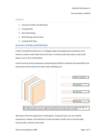
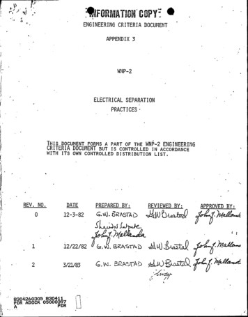
DensGlass Shaftliner Area Separation WallsProduct OverviewCoatedFiberglass MatsMoisture-ResistantGypsum CoreDensGlass Shaftliner 2014 Georgia-Pacific Gypsum LLCDensGlass Shaftliner has fiberglass mats for superior mold and moisture resistancecompared to paper-faced shaftliners. Fiberglass mats eliminate a potential food source for mold and may reduce remediationand scheduling delays associated with paper-faced shaftliners. Replaces traditional paper-faced shaftliner in area separation wall systems. Backed with a limited warranty against delamination and deterioration for up to 12 monthsof exposure to normal weather conditions.**For complete warranty details, visit www.gpgypsum.com.When tested, as manufactured, in accordance with ASTM D 3273, DensGlass Shaftlinerpanels have scored a 10, the highest level of performance for mold resistance under theASTM D 3273 test method.Table of ContentsOverview . . . . . . . . . . . . . . . . 2ArchitecturalSpecifications . . . . . . . . . . . . 3Installation Instructions . . . . . 5Special Conditions . . . . . . . . . 6Fire-Rated Assemblies. . . . . . 7Details . . . . . . . . . . . . . . . . . . 8Delivery, Handlingand Storage . . . . . . . . . . . . . 14Commonly UsedMetric Conversions . . . . . . . 152 For latest information and updates:The score of 10, in the ASTM D 3273 test, indicates no mold growth in a 4-weekcontrolled laboratory test. The mold resistance of any building product, when used inactual job site conditions, may not produce the same results as were achieved in thecontrolled, laboratory setting. No material can be considered mold proof. When properlyused with good design, handling and construction practices, Dens Brand gypsum productsprovide increased mold resistance compared to standard paper-faced wallboard. Foradditional information, go to www.buildgp.com/safetyinfo.DensGlass Shaftliner is listed as a GREENGUARD microbial-resistant product by ULEnvironment. This listing means DensGlass Shaftliner, which features fiberglass matsinstead of the paper facings used on the surface of traditional gypsum board products,resists mold growth. The microbial-resistant test is based on ASTM D 6329, a guide setby ASTM International, which develops testing guidelines and procedures for buildingmaterials, products, systems and services.Technical Service Hotline 1.800.225.6119 or www.gpgypsum.comCAUTION: For product fire, safety and use information,go to buildgp.com/safetyinfo.
DensGlass Shaftliner Area Separation WallsThe Area Separation Wall assembly using Georgia-Pacific Gypsum DensGlass Shaftliner is designed for use in multi-family,multi-story townhouses as a firewall with a total height up to 68’ (20,726 mm) or a total height of up to 44’ (13,411 mm) forUL ITS/WHI. Because it is constructed using gypsum board, the assembly is easy to erect, secure and provides economicalfire protection and sound control. DensGlass Shaftliner conforms to the requirements of the IRC and IBC for use in the AreaSeparation Wall assembly.The Area Separation Wall is constructed once the framing for one townhouse unit is complete and prior to the construction ofthe adjacent unit. The assembly is constructed at the foundation and continues either to the underside of the protected roofsheathing or through the roof to form a parapet. The assembly is linked to the adjacent framing with aluminum breakaway clipsthat allow for collapse of the fire-exposed unit without collapse of the solid Area Separation Wall.Because the assembly will be exposed to the elements during construction, Georgia-Pacific Gypsum offers increased protectionto the owner, builder and architect with a moisture- and mold-resistant shaftliner panel: DensGlass Shaftliner.Georgia-Pacific Gypsum and SustainabilityGeorgia-Pacific Gypsum’s definition of sustainability is meeting the needs of society today without jeopardizing our ability to do soin the future. We are committed to using resources efficiently to provide innovative products and solutions that meet the needsof customers and society, while operating in a manner that is environmentally and socially responsible, and economically sound.We continue to focus on: Improving energy efficiency at our manufacturing plants Seeking out opportunities to reduce water use, and to reuse water more efficiently Finding cost effective ways to further reduce air emissions Recovering and reusing materials that otherwise would end up in landfills.Green building codes, standards, and programs are establishing themselves across the country. They promote the use of productsthat contribute to the performance of the building, along with minimizing environmental and human health impacts over the lifeof the building or home. Because we embrace product performance and operate in an environmentally, socially, and economicallysound manner, owners and architects can feel good about the structures they build using our products.Many of our products contribute to LEED and other green building codes, standards, or program credits or requirements. To findout more, please refer to the Sustainable Materials Data Sheets (SMDS) at www.gpgypsum.com for recycled content, regionalmaterials, and low emitting materials information or use our on-line LEED calculator to calculate contribution for a specific credit.For general information on sustainability, click the “Sustainability” tab on the website.Architectural SpecificationsGeorgia-Pacific Gypsum’s 3-part guide specifications are downloadable, as rewritable Microsoft Word documents, in bothCSI and ARCOM MasterSpec formats. Georgia-Pacific Gypsum specifications and 3-D Revit compatible models can befound at www.gpdesignstudio.com. Downloadable specifications are also available online from Building Systems Design, Inc. atwww.bsdsoftlink.com, and ARCOM Product Masterspec at www.masterspec.com.CAUTION: For product fire, safety and use information,go to buildgp.com/safetyinfo.For latest information and updates:Technical Service Hotline 1.800.225.6119 or www.gpgypsum.com3
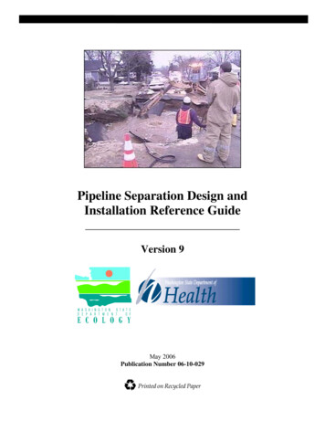
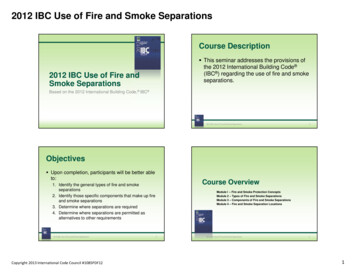
DensGlass Shaftliner Area Separation WallsComponents2x4 Wood FramingTwo 1” (25.4 mm) DensGlass Shaftliner PanelsBatt InsulationMin. 3/4” (19 mm) air space between 2” (51 mm)Area Separation Wall and Wood Framing2” (51 mm) H-Studs 24” (610 mm) o.c.1/2” (12.7 mm) DensArmor Plus Interior Panel or 1/2” (12.7 mm) ToughRock Gypsum BoardBack-to-back C-TracksAluminum Breakaway ClipFire Blocking per CodeThe Area Separation Wall is constructed using 1” (25.4 mm) thick, 24” (610 mm) wide DensGlass Shaftliner panels, 25-gauge(18 mils) steel H-studs, 25-gauge (18 mils) steel C-track and 2” (51 mm) aluminum breakaway clips. DensGlass Shaftliner panelsconsist of a moisture-resistant core with coated fiberglass mats front and back instead of paper facings like traditional shaftlinerpanels. DensGlass Shaftliner panels are backed by a limited warranty against delamination and deterioration for up to 12 monthsof exposure to normal weather conditions and a limited warranty against manufacturing defects for five years from date ofpurchase. For additional warranty details, go to www.gpgypsum.com.Fire Testing and Building Code ComplianceThe Area Separation Wall has been fire tested to ASTM E 119 and CAN/ULC S-101. The 2-hour fire-rated Area Separation Wallassembly, using DensGlass Shaftliner panels, is listed by UL, ULC and ITS/WHI and meets the requirements of the InternationalBuilding Code (IBC) Section 706, “Fire Walls.” The Area Separation Wall assembly using DensGlass Shaftliner panels is listed inthe UL Fire Resistance Directory under UL Design U373, the ULC Fire Resistance Directory ULC Design No. W312 and the WHIFire Resistance Directory under WHI GP/WA 120-04. Consult the applicable fire resistance directory for additional information.4 For latest information and updates:Technical Service Hotline 1.800.225.6119 or www.gpgypsum.comCAUTION: For product fire, safety and use information,go to buildgp.com/safetyinfo.
DensGlass Shaftliner Area Separation WallsInstallation InstructionsThe Area Separation Wall is constructed once the framing for one townhouse unit is complete and prior to the construction of theadjacent unit. The solid 2” (51 mm) Area Separation Wall is constructed a minimum 3/4” (19 mm) away from the adjacent framing,which is typically constructed from wood. In many cases the area separation wall is positioned 1” (25.4 mm) away from the wallframing to accommodate the 1” (25.4 mm) DensGlass Shaftliner panels used as fireblocking between the floor levels. TheUL Design U373 Area Separation Wall assembly was evaluated at a height up to 44’ (13,411 mm) and the ITS/WHI GP/WA 120-04Area Separation Wall assembly was evaluated at a height up to 68’ (20,726 mm). To view installation video, visithttp://www.gpgypsum.com (DensGlass Shaftliner).Erecting the 2” (51 mm) Area Separation Wall1. Position 2” (51 mm) C-Track a minimum 3/4” (19 mm) from the framed wall of the adjacent unit. Fasten C-Track to foundation withfasteners spaced a maximum of 24” (610 mm) o.c. When specified, apply a minimum 1/4” (6 mm) bead of acoustical sealant under theC-Track to maximize acoustical privacy. Run the C-Track to the end of the foundation. In case of offset units, see 15 under Special Conditions.2. Start the wall with a vertical C-Track at one end. Install two 1” (25.4 mm) shaftliner panels vertically with either side facing out* into theC-Track at one end of the area separation wall. Install the H-stud over the double beveled edges of the shaftliner panels and continuealternately until the wall has reached the opposite end of the foundation. Terminate the wall using a C-Track. The vertical C-Tracks ateach end of the wall should be attached in the corners to the horizontal sections of the C-Track using a minimum of one 3/8” (9 mm)minimum length pan head screw.* Note: Some authorities may require labeling to be visible.3. Cap the first section of the Area Separation Wall with a C-Track and attach to the vertical C-Track in the corners using a minimum ofone 3/8” (9 mm) minimum length pan head screw.4. Breakaway clips span the minimum 3/4” (19 mm) air space and provide a fusible link between the H-studs and the adjacent wallframing. Attach the breakaway clips to the flange of the H-stud using a minimum of one 3/8” (9 mm) minimum length pan head screwand to the adjacent wood framing using a minimum of one 1” (25.4 mm) minimum length drywall screw.* When the UL Design U373 Area Separation Wall assembly is specified, the breakaway clips should be located vertically at each floorlevel 10’0” (3048 mm) o.c. and horizontally on every H-stud 24” (610 mm) o.c. When the total height of the Area Separation Wallexceeds 23’ (7010 mm), breakaway clips shall be installed every 5’0” (1524 mm) for the lower 20’ (6096 mm) and every 10’0” (3048 mm)for the upper 24’0” (7315 mm) of the wall assembly. Breakaway clips are installed on both sides of the Area Separation Wall.* When the ITS/WHI Design WHI GP/WA 120-04 Area Separation Wall assembly is specified, the breakaway clips should be locatedvertically at each floor level 10’0” (3048 mm) o.c. and horizontally on every other H-stud or 48” (1219 mm) o.c. When the total heightof the Area Separation Wall exceeds 20’0” (6096 mm), breakaway clips shall be installed vertically every 8’0” (2438 mm) maximum forthe lower 20’0” (6096 mm) and every 10’0” (3048 mm) maximum for the upper 48’0” (14630 m) of the wall assembly.5. Fireblocking is installed on both sides of the Area Separation Wall at each floor level as defined in the IBC. (See Details section.) Forapproved fire-blocking materials, see Special Conditions, Item 8.6. To continue the wall, install a C-Track over the C-Track used to cap the lower section, placed back to back and attached together withtwo 3/8” (9 mm) pan head screws at ends and spaced 24” (610 mm) o.c. Stagger back-to-back C-Track joints a minimum of 12” (305 mm).7. If a parapet is not specified, see Special Conditions, Item 11 for two methods for installing a gypsum board roof underlayment. Consultwith local code authority for proper method.8. Once the 2” (51 mm) Area Separation Wall is erected, construction of the adjacent interior wall framing can begin. Breakaway clip andfire-blocking installation is identical for both sides of the 2” (51 mm) Area Separation Wall.9. Do not install insulation in the system until the building has been properly closed in.* Consult the fire resistancedirectory or test report forcomplete assembly information.For additional fire safety informationconcerning DensGlass Shaftliner,visit www.buildgp.com/safetyinfo.Aluminum Angle Clip2-1/2”(64 mm)CAUTION: For product fire, safety and use information,go to buildgp.com/safetyinfo.C-Track, Cap, Edgeor End Closure2-1/4”(57 mm)H-Stud, 25-Gauge (18 mils)2”(51 mm)For latest information and updates:Technical Service Hotline 1.800.225.6119 or www.gpgypsum.com5
DensGlass Shaftliner Area Separation WallsSpecial Conditions1. When an H-Stud does not align with the adjacent wood framing, insert blocking between wood framing members andattach breakaway clip to blocking using one 1-1/4” (32 mm) drywall screw and to the H-Stud using a minimum of one3/8” (9 mm) minimum length pan head screw.2. If gaps are present between back-to-back C-Tracks, caulk using appropriate fire caulking material.3. When wall framing is spaced greater than 1” (25.4 mm) away from the solid 2” (51 mm) Area Separation Wall, aluminumclips with longer legs are permitted. Contact clip manufacturers for modified clips. Additional wood blocking can beadded between the wood studs to provide clip support. Space wood blocking minimum 3/4” (19 mm) away from AreaSeparation Wall.4. The solid 2” (51 mm) Area Separation Wall is non-load bearing. The adjacent framed wall can be designed as load bearing.5. The wall located adjacent to the solid 2” (51 mm) Area Separation Wall, a minimum of 3/4” (19 mm) away, can beconstructed of wood or steel framing. When constructed using steel framing, use a minimum of one 3/8” (9 mm)minimum length pan head screw to attach the aluminum breakaway clip.6. The support walls located adjacent to, and on each side of the solid 2” (51 mm) Area Separation Wall protect and maintainthe required 3/4” (19 mm) air space, offer increased acoustical privacy and provide necessary aesthetics. These walls can bedesigned as load bearing and readily accommodate electrical and plumbing systems. These systems should not impede therequired 3/4” (19 mm) air space. Apply acoustical sealant around penetrations for maximum acoustical privacy.7. The required 3/4” (19 mm) air space can be eliminated if the metal framing is covered on both faces with 6” (152 mm)wide, 1/2” (12.7 mm) DensArmor Plus Fireguard C or 1/2” (12.7 mm) ToughRock Fireguard C or 5/8” (15.9 mm)ToughRock Fireguard X or 5/8” (15.9 mm) DensArmor Plus Fireguard gypsum board strips. The gypsum board stripsare attached with 1” (25.4 mm) drywall screws spaced 12” (305 mm) o.c. to the metal framing. This primarily occurs inaccessible attic areas. Attic areas not accessible do not require the 6” (152 mm) wide gypsum board strips.8. The required fireblocking between floor levels may consist of 2” (51 mm) nominal lumber, or two thicknesses of 1” (25.4 mm)nominal lumber with broken lap joints, or one thickness of 0.719” (18.3 mm) wood structural panel with joints backed by0.719” (18.3 mm) wood structural panel, or one thickness of 0.75” (19 mm) particleboard with joints backed by 0.75” (19 mm)particleboard. Gypsum board, including 1” (25.4 mm) DensGlass Shaftliner and 5/8” (15.9 mm) DensArmor Plus interiorpanel, batts or blankets of mineral wool or fiberglass or other approved materials installed in such a manner as to besecurely retained in place shall be permitted as an acceptable fireblock (per Chapter 7 of the IBC).9. The Area Separation Wall assembly can be constructed with or without a parapet.10. At the intersection of the solid 2” (51 mm) Area Separation Wall and the underside of the structural roof sheathing, cut linerpanels at an angle to provide a tight fit to the structural sheathing. The 2” (51 mm) Area Separation Wall is not requiredto be capped using a C-Stud. Where the shaftliner panels are not tight to the structural sheathing, apply an approvedfireblocking material (see Special Conditions, Item #8) to both sides of the Area Separation Wall.11. There are two methods for installing a fire-resistant roof underlayment: the ledger strip method and the partial roofunderlayment method. Consult with local code authority for proper method. In the ledger strip method, one layer of 5/8” (15.9mm) DensArmor Plus Fireguard interior panel or 5/8” (15.9 mm) ToughRock Fireguard X gypsum board is placed 4’ (1219mm) on both sides of the Area Separation Wall. The gypsum board is cut to fit tight between the roof framing members.Nominal 2” (51 mm) x 2” (51 mm) wood ledger strips hold the gypsum board snug to the underside of the roof sheathing andflush with the top of the roof framing. The ledgers are attached to the roof framing and form a continuous strip. The secondmethod is using fire-treated plywood at least 4’ (1219 mm) on both sides of the Area Separation Wall.12. Penetrations through the solid 2” (51 mm) Area Separation Wall should be protected in accordance with Chapter 7 of theIBC. For specific installation details consult UL category XHEZ Through-penetration Firestop Systems.13. Size and protection of openings in the solid 2” (51 mm) Area Separation Wall shall be in accordance with the IBC,Section 706. When the Area Separation Wall is designed as a Party Wall (“Any wall located on a property line betweenadjacent buildings, which is used or adapted for joint service between the two buildings.”) as listed in the IBC, Section706, openings are not permitted.14. For specialized end-use areas, such as bathrooms, the adjacent framed walls can be covered with DensShield TileBacker from Georgia-Pacific in lieu of standard paper-faced gypsum board or fiberglass mat-faced interior panels.6 For latest information and updates:Technical Service Hotline 1.800.225.6119 or www.gpgypsum.comCAUTION: For product fire, safety and use information,go to buildgp.com/safetyinfo.
DensGlass Shaftliner Area Separation WallsSpecial Conditions continued15. An offset occurs when one unit extends past the front or back edge of an adjacent unit. The H-studs of the Area SeparationWall are not designed for hanging sheathing and cladding, so planning is required before construction begins. There aretwo ways to deal with the offset. The first option is to pour enough concrete so that the Area Separation Wall and adjacentframed wall can extend to the furthest most point. Sheathing and cladding can then be installed to the adjacent framed wall.The second option is to terminate the Area Separation Wall at the end of the shared wall and then construct a one-hour wallto the end of the offset unit. Both scenarios are shown in the Details section of this brochure.16. Provide for deflection of live loaded floor assemblies by using relief joints or floating trim.Fire-Rated AssembliesDensGlass Shaftliner is UL and ULC classified as Type DGUSL and included in numerous assembly designs investigated byUL and ULC for hourly fire resistance ratings.In addition, DensGlass Shaftliner is classified as “Type X” in accordance with ASTM C 1658. “Type X” as used in this technicalguide designates gypsum board manufactured and tested in accordance with specific ASTM standards for increased fireresistance beyond regular gypsum board. Please consult the ASTM standard for the specific product (for example, ASTM C1658 for glass mat interior panels) for further information and significance of use.The following design assemblies are for illustrative purposes only. Consult the fire resistance directory or testreport for complete assembly information. For additional fire safety information concerning DensGlass Shaftliner,visit www.buildgp.com/safetyinfo.System Assemblies – 2-Hour Ratings – Area Separation Walls2-Hour Fire RatingDesign Reference: UL U373, ULC W312,WHI GP/WA 120-03, cUL U37359 STC Sound Trans.Test Reference: RAL TL 10-290Two layers 1” (25.4 mm) DensGlass Shaftliner inserted in H-Studs 24” (610 mm)o.c. Min. 3/4” (19 mm) air space between liner panels and adjacent wood ormetal framing.Sound Tested with 2”x 4” stud wall with 1/2” (12.7 mm) ToughRock wallboardor DensArmor Plus interior panels and 3-1/2” (89 mm) fiberglass insulation instud space.2-Hour Fire RatingDesign Reference: UL U373, ULC W312,WHI GP/WA 120-04, cUL U373, GA ASW 081066 STC Sound Trans.Test Reference: RAL TL 10-291Two layers 1” (25.4 mm) DensGlass Shaftliner inserted in H-Studs 24” (610 mm)o.c. Min. 3/4” (19 mm) air space on both sides must be maintained between linerpanels and adjacent framing.Sound Tested with 2”x 4” stud wall with 1/2” (12.7 mm) ToughRock gypsumwallboard or DensArmor Plus interior panels each side of assembly and 3-1/2”(89 mm) fiberglass insulation in stud space both sides.2-Hour Fire RatingDesign Reference: WHI 495-074338 STC Sound Trans. Est.Part. Thickness: 3” (76 mm)Weight per Sq. Ft.: 9.5 (46 Kg/m2)Two layers 1” (25.4 mm) DensGlass Shaftliner inserted in H-Studs 24” (610 mm) o.c.Metal covered using 6” (152 mm) wide 1/2” (12.7 mm) DensArmor Plus Fireguard C interior panels or 1/2” (12.7 mm) ToughRock Fireguard C gypsum board.CAUTION: For product fire, safety and use information,go to buildgp.com/safetyinfo.For latest information and updates:Technical Service Hotline 1.800.225.6119 or www.gpgypsum.com7
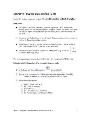
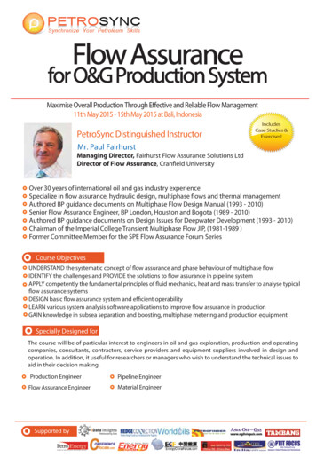
DensGlass Shaftliner Area Separation WallsDetailsThe following assemblies and details are for illustration purposes only. Please consult design authority and confirm codecompliance. Georgia-Pacific Gypsum does not provide design services.ABCNivel delsueloGroundLevelSótano de2286-2438 mmBasement(7’6” – 8’)7’6”- de8’ altura(2286-2438 mm)HighDMuro de concreto vertidoPoured Concrete WallA. Roof-Ceiling 2014Georgia-PacificGypsumParapet CapB. Exterior Wall IntersectionLLCFire BlockingExterior WallMinimum height as required by codeFiberglassBatt Insulation3/4" (19 mm)minimumAir Space2 Sheets of 1"(25.4 mm) DensGlass Shaftliner(Firewall)RoofingFlashingBreakaway Clip1/2" (12.7 mm) DensArmor Plus Panel or1/2" (12.7 mm) ToughRock gypsum boardFloor JoistBreakaway ClipFiberglassBatt Insulation8 For latest information and updates:2" (51 mm) H-StudFiberglassBatt InsulationCladding1/2" (12.7 mm) DensArmor Plus Panel or1/2" (12.7 mm) ToughRock WallboardD. Wall-to-Slab2 Sheets of1" (25.4 mm) DensGlassShaftliner(Firewall)Double C-ShapedMetal Track ScrewedBack to BackSubfloorSpace for AcousticalSealant (as required)3/4" (19 mm) minimumAir SpaceC-Shaped MetalTrack Set in Sealantto Create aSmoke-Tight Joint(as required)C. Floor Intersection2 Sheets of1" (25.4 mm) DensGlassShaftliner (Firewall)1/2" (12.7 mm) DensArmor Plus Panel or1/2" (12.7 mm) ToughRock gypsum board2 Sheets of1" (25.4 mm) DensGlass Shaftliner (Firewall)3/4" (19 mm) minimumAir SpaceFire Blocking(as required by code)TopPlate1/2" (12.7 mm) DensArmor Plus Panel(Ceiling) or 1/2" (12.7 mm) ToughRock gypsum board (Ceiling)3/4" (19 mm) minimum Air SpaceTechnical Service Hotline 1.800.225.6119 or www.gpgypsum.com1/2" (12.7 mm) DensArmor Plus Panelor 1/2" (12.7 mm) ToughRock gypsum boardFiberglassBatt Insulation2x4 PlateC-shapedMetal TrackSpace for AcousticalSealant (as required)Concrete SlabCAUTION: For product fire, safety and use information,go to buildgp.com/safetyinfo.
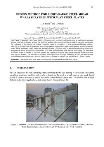
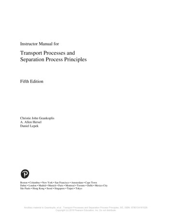
DensGlass Shaftliner Area Separation WallsDetailsFull WallFire blocking as requiredRoof deck per code requirementRoof truss2 x 4 Stud framingIntersection at roofAluminum breakaway clipBack-to-back C-tracks3/8” (9.5 mm) Pan head screwSealant1-1/4” (31.8 mm) Drywall screwIntermediate floorAcoustic sealant (as required)Joist1” (25.4 mm) DensGlass Shaftliner panels2” (51 mm) C-track fastener24” (610 mm) o.c.Sealant, as requiredCAUTION: For product fire, safety and use information,go to buildgp.com/safetyinfo.FoundationFor latest information and updates:Technical Service Hotline 1.800.225.6119 or www.gpgypsum.com9
DensGlass Shaftliner Area Separation WallsDetailsAttic–Adjacent to Trusses*1” (25.4 mm) DensGlass Shaftliner panelsH-studNo minimum air spaceWood truss*Only applies if solid wall is accessible.If not accessible, the strips are not required.6” (152 mm) wide 1/2” (12.7 mm)DensArmor Plus Fireguard C panels or1/2” (12.7 mm) ToughRock Fireguard C or5/8” (15.9 mm) DensArmor Plus Fireguard or5/8” (15.9 mm) ToughRock Fireguard X or1” (25.4 mm) DensGlass Shaftliner panelsTypical Roof Junction1 Layer of 5/8” (15.9 mm)DensArmor Plus Fireguard gypsumpanel (or as required by codes)2” (51 mm) x 2” (51 mm)ledger stripsCaulk (smoke tight joint)RoofingRoof deckBreakaway clipFire blockingInsulation1/2” (12.7 mm) DensArmorPlus gypsum panel or1/2” (12.7 mm)ToughRock gypsum board3/4” (19 mm) Minimum air space1” (25.4 mm) DensGlassShaftliner panels10 For latest information and updates:Technical Service Hotline 1.800.225.6119 or www.gpgypsum.comCAUTION: For product fire, safety and use information,go to buildgp.com/safetyinfo.
DensGlass Shaftliner Area Separation WallsDetailsTypical Offset Roof—1 HourRoofingExternal Cladding5/8” (15.9 mm) DensGlass Fireguard SheathingFlashingRoof Deck5/8” (15.9 mm)DensArmor Plus Fireguard panel or 5/8” (15.9 mm)ToughRock Fireguard X Insulation3/4” (19 mm) airspaceFire blocking(as required by code)1” (25.4 mm)DensGlass Shaftliner panelsTypical Offset Roof—2 HourRoofingRoof deckExternal CladdingBreakaway clip5/8” (15.9 mm) DensGlass Fireguard SheathingFlooring1/2” (12.7 mm) DensArmorPlus panel or 1/2” (12.7 mm)ToughRock gypsum board3/4” (19 mm) Minimumair space1” (25.4 mm) DensGlassShaftliner panelsCAUTION: For product fire, safety and use information,go to buildgp.com/safetyinfo.Roof DeckInsulation (optional)Fire blocking(as required by code)For latest information and updates: 11Technical Service Hotline 1.800.225.6119 or www.gpgypsum.com
DensGlass Shaftliner Area Separation WallsDetailsTypical Offset Wall—1 Hour1” (25.4 mm) DensGlass Shaftliner panels3/4” (19 mm) airspace1/2” (12.7 mm) DensArmor Plus panel or1/2” (12.7 mm) ToughRock gypsum boardC-Track5/8” (15.9 mm)DensArmor Plus Fireguard panel or 5/8” (15.9 mm)ToughRock Fireguard X 5/8” (15.9 mm)DensGlass Fireguard Sheathing5/8” (15.9 mm)DensGlass Fireguard SheathingExteriorCladding5/8” (15.9 mm)DensGlass SheathingTypical Offset Wall—2 Hour5/8” (15.9 mm) DensGlassFireguard Sheathing1” (25.4 mm) DensGlassShaftliner panels3/4” (19 mm)Minimum air spaceDensGlass Sheathing1/2” (12.7 mm) DensArmor Pluspanel or 1/2” (12.7 mm)ToughRock gypsum boardInsulation12 For latest information and updates:Technical Service Hotline 1.800.225.6119 or www.gpgypsum.comBreakaway clipInsulation optionalCAUTION: For product fire, safety and use information,go to buildgp.com/safetyinfo.
DensGlass Shaftliner Area Separation WallsDetailsCantilever DetailBack-to-back C-Tracks mechanically attached witha 3/8” (9 mm) pan head screw 24” (610 mm) o.c.C-TrackCeiling2” (51 mm) wide 25-gauge (18 mils) steel strapmechanically attached to each H-stud.It crosses with a 3/8” (9 mm) pan head screwon both sides of solid 2” (51 mm) gypsum shaftwall. Use two screws at ends.H-Studs spaced 24” (610 mm)1” (25.4 mm) DensGlass Shaftliner panels2 layers 5/8” (15.9 mm) DensGlass Fireguard Sheathing gypsum board for thesoffit within 4’ (1219 mm) of property line.C-TrackBack-to-back C-Track screen mechanically attachedwith a 3/8” (9 mm) pan head screw 8” (203 mm) o.c.Use two screws at top near corners.3’ (914 mm) max.CAUTION: For product fire, safety and use information,go to buildgp.com/safetyinfo.For latest information and updates: 13Technical Service Hotline 1.800.225.6119 or www.gpgypsum.com
DensGlass Shaftliner Area Separation WallsDelivery, Handling and StorageAll materials shall be delivered in original bundles bearing the brand name, if any; applicable standard designation; and name ofthe manufacturer or supplier for whom the product is manufactured. The plastic packaging used to wrap gypsum panel productsfor rail and/or truck shipment is intended to provide temporary protection from moisture exposure during transit only and is notintended to provide protection during storage after delivery. Such plastic packaging shall be removed immediately upon receiptof the shipment. WARNING: Failure to remove protective plastic shipping covers can result in condensation which can lead todamage, including mold.All materials should be kept dry. Gypsum panel products shall be neatly stacked flat with care taken to prevent sagging ordamage to edges, ends and surfaces. Gypsum panel products and accessories shall be properly supported on risers on a levelplatform, and fully protected from weather, direct sunlight exposure and condensation. Gypsum panel products shall be stackedflat rather than on edge or end. WARNING: Gypsum panel products stacked on edge or end can be unstable and present aserious hazard in the workplace should they accidentally topple.Refer to Handling Gypsum Panel Products, GA-801, for proper storage and handling requirements.Reference: Application and Finishing of Gypsum Panel Products, GA-216, Gypsum Association.14 For latest information and updates:Technical Service Hotline 1.800.225.6119 or www.gpgypsum.comCAUTION: For product fire, safety and use information,go to buildgp.com/safetyinfo.
DensGlass Shaftliner Area Separation WallsCOMMONLY USED METRIC CONVERSIONSGypsum Board Thickness1/4 in. – 6 mm1/2 in. – 12.7 mm5/8 in. – 15.9 mm1 in. – 25.4 mmGypsum Board Width2 ft. – 610 mm4 ft. – 1219 mm32 in. – 813 mmGypsum Board Length4 ft. – 1219 mm5 ft. – 1524 mm8 ft. – 2438 mm9 ft. – 2743 mm10 ft. – 3048 mm12 ft. – 3658 mmCAUTION: For product fire, safety and
DensGlass Shaftliner Area Separation Walls For latest information and updates: Tec