Transcription
FORM meENG INEERINGCoPV CRITERIADOCUf'1ENTAPPENDIX 3WNP-2ELECTRICAL SEPARATIONPRACTICESTHIS DOCUMENT FORMS A PART OF THE WNP-2 ENGINEERINGCRITERIA DOCUf'lENT BUT IS CONTROLLED IN ACCORDANCEWITH ITS OWN COiVTROLLED DISTRIBUTION LIST,REV. NO,DATE12-3-82PREPARED BY;c'.a).Gents)ERAS tt'D12/22/823/21/838304260305 8304%iPDR ADOCK 05000397AIPDRQg, 1/s,Btl i, I4REVIEWED BY:APPROVED BY:g[tJ iz g4L'UMMg)PaJ8
tlpIl) I)
WNP-2ELECTRICAL SEPARATION PRACTICES PeI.PurposeXI.Electrical Separation CriteriaA.DefinitionsBEClass .1E Redundant1.2.CircuitDesign RequirementsSpatial Separation Between RacewaysSpatial Separation Within EnclosuresandEquipmentC.3.4.5.Separation for Fail-Safe SystemsSeparation Within DivisionsRaceway, Cable, Equipment, and Enclosures6.7.8.Transient Data Acquisition System1.2.3 D.III IdentificationGeneral Plant/PGCC InterfaceIsolation DevicesAssociatedPrimeCircuitDesign RequirementsCircuits1ECircuitDesign RequirementsCri teri a on-Class 1E, Non-DivisionalE.General Plant/PGCC Interface1E'A14141415151617182021Circuits.Tables and FiguresAppendix1010121220CircuitsA.IV. Ref erencesV.(TDAS)Proximity CircuitsPrime and Proximity Circuit IdentificationNon-Classe Ne.- Field VerificationCircuits22222223A-1/A-13
I.Purposeof this document is to clarify the WNP-2 electrical separation criteria, describe practices used to implement the criteria, and to provide sufficient information in a manner to simplify verification of implementation inthe field. There are no differences in the design criteria between this docu-The purpose-ment and the WNP-2 FSAR.This document should be used by engineers,sonnel and operations personnel.II. ion CriteriaDefinitionsClass1Eis the safety classification of the electrical circuits,components, equipment and systems that are essential to emergencyreactor shutdown, containment isolation, reactor core cooling, andClass lEcontainment and reactor heat removal, or otherwise preventcant release of radioactive material to the environment.20Powersignifi-CizcuitsPower circuits provide electrical energy for component motive powerand heating requiring 14.4 kV, 6.9 kV, 4.16 kV, 480 volts, 240 volts,for details) 120/208 V AC, 250 and 125 V DC (see TableI3 Control CircuitsControl circuits use 120 V AC (or below) or 125 V DC (or below), andare designed to supply control power for plant systems. The largestcontrol circuit protective device (fuse/breaker) has .a 35 amp rating.The majority of the control circuits are intermittent in operation'.Control circuits include the following functions (see Table I fordetails):.a.125 VDCorlocal panels,orcontrol to switchgear, controllogic interlock circuits.120 V ACandb.125 Vc.Annunciator/computerSpaceDC120 V ACcontroldigitalpower tozoom andsolenoids.circuits'.heaters including motor heaters.to the 35 amp maximum rating exist; two 100 ampbreakers and a 60 amp breaker for circuits in the ReactorProtection System and the Reactor Manual Control System. Within theGeneral Plant Areas these circuits are routed separately in rigidconduit. Within PGCC these circuits are routed separately 'nflexible conduits with an attached ground conductor.Three exceptionscircuit4.Instrumentation CircuitsInstrumentation circuits are low level analog ordigital signals.
5.Low EnergyCircuitsLow energycircuitsare control and instrumentationcircuits'.Isolation DeviceAnisolation device preventsancircuit from causing unacceptablethe circuit or other circuits.7.electricalevent in one section ofconsequencesain other sections ofRacewayFor the purposes of this document, raceways shall include open or.enclosed cable trays, flexible and rigid conduit (not EMT) and PGCCmodular flooi dupts. Device/component nipples and conduits up to thefirst tee are not included in this definition but shall be consideredas part of the device/component.8.Associated CircuitsAssociatedasa.follows:Primecircuitsare defined aseither prime or proximity circuitsCircuitsNonMlass 1E circuit which receives power from a Class 1EsourceThe circuit begins at the load side of the source circuitprotective device (isolation device), through the interconnecting .cables, and up to the final connected load. The portion of aprime circuit which is routed in a Class 1E raceway is additionally termed "Associated By Proximity".Ab.Proximity Circuitsproximity circuit is a NonWlass lE circuit which is routed(along any portion of its length) in a raceway with a Class lEcircuit or is contained in an enclosure with Class lE circuits andphysically routed less than 6" from a Class 1E circuit (withoutbarrier) The portion of the proximity circuit whichis routed in a Class 1E raceway is termed "Associated ByProximity". Ef the circuit leaves the Class 1E raceway, the circuit is termed and treated as Non&lass lE unless the circuit isalso prime (see Figure 4).A 9.an'ppropriateRedundantFor the purposes of this document redundant, shall refer to the collection of Class 1E circuits, components, equipment, etc. (system(s ) )performing a specific plant safety function which is a backup to otherClass 1E system(s) independently performing the same safety function.Safety functions, are Emergency Reactor Shutdown, ContainmentIsolation, Reactor Core Cooling, Containment, and Reactor Heat Removal,and Offsite Radioactive Release prevention.For example, the LowPressure Core Spray System is redundant to the Residual"Heat RemovalSystem (Low Pressure Coolant injection mode) Loop C for the "ReactorCore Cooling" safety function.
10.'ntruding CircuitsIntruding circuits are of two types: 1) Class 1E or prime circuitswhich enter equipment or an enclosure or an area (either subenclosures or as defined by lines of demarcation) of an enclosureassigned to a redundant Class 1E or prime division, 2) Redundantprime circuits which enter common equipment or enclosures assigned toa NonMlass 1E divisions one of these becomes intruding. Forexample, Division A prime and Division B prime circuits within aDivision A panel requires the Division B prime circuit be treated asan11intruder.'arrierbarrier is material or a structure placed between redundant ClasslE or prime equipment or circuits to limit damage to Class 1E circuits from internally generated fires. Within enclosures and equipment barriers are Haveg Siltemp tape or sleeving, conduits (flexibleor rigid) and sheet metal enclosures or metal plates. Outside enclosures and equipment barriers are solid steel tray covers and bottoms,sheet metal panels, Thermolag insulation, and conduits (flexible inminiducts, PGCC periphery, or where flexibility is necessary, orArigid).12.Power GenerationControl Complex(PGCC)PGCC located in the Main Control Room is defined for the purposesof this document as a modular assembly of termination cabinets interconnected'y floor sections comprised of multiple, separate cableducts on which are mounted control room panels. The„PGCC forms aninterface between the incoming plant cables and control zoom panels.ThePeriphery of13.PGCCperiphery of the PGCC is defined as the subfloor area between thetermination cabinets and the Main Control Room wall.TheDirect Bridging14.Direct bridging is defineddantClass1Eracewaysas acircuit(see Figurewhich routes between redun-lA). Direct bridging is prohi-bited'5."Secondary Bridging By ProximitySecondaz'ya.b.bridgingbyproximity is defined as:Bridging of redundant, Class 1E1E (Division A, B, XXX1, XXX2,together in a common enclosureof their routing in a redundantcircuitsby two (or more) NonMlassproximity circuits, routedor raceway, and each having partorXXX3)Class1Eraceway (See Figure 1B).Bridging of redundant Class 1E circuits by Non-Class 1E (DivisionA, B, XXX1, XXX2, or XXX3) proximity circuits within enclosuresoz equipment.These proximity circuits may also be extensions ofcircuits originating from Class 1E raceways (See Figure 1C)
,16.Fail»Safe Systemsfail-2Systems used to shutdown (SCRAM) the reactor are designed tosafe upon loss of power(de-energize-to perate) These systems arethe Reactor Protection System (RPS) and those portions of the NeutronSource Range Monitoring (SRH), InterHonitoring System (NHS)mediate Range Monitoring (ZRM), Average Power Range Monitoring (APRM) f,and Local Power Range Monitoring (LPRM) providing input to the RPS.In addition, system inputs and logic'associated with the containmenti.e.,isolation function are designed to17.fail-safe.beEquipment and Enclosuresof this document equipment and enclosures aredefined as panels, racks including open faced instrument racks, terminal boxes, etc. Individual device/component housings which includethe conduit nipple up'to the first tee are not included in thisFor the purposes2definition18.Residing/Compatible Division Wiringsame division as that designated for theequipment/enclosure (residing) or is acceptable to be routed withequipment or enclosure residing wires (compatible) All other wiringWiring of theis intruding.B.Classf1ERedundantCircuitDesign RequirementsEach Class 1E component and interconnecting cabling shall be assigned toone of seven Class lE divisions as noted in Table 'IZ. Class lE componentsof one division are separated from Class 1E components of other redundantdivisions. .Minimum separation distances for trays, conduits, cables, andcables/wires within enclosures are described below. Note that the separation distances specified are to preclude internally generated fire propagation between redundant Class 1E divisions and do not consider effects of'externally generated fires or pipe'reaks1 Spatial Separationa)andmissiles.Between RacewaysGeneral Plant Areas (OutsidePGCC)'Distances shown consider the ideal arrangement of two (2)raceways only. If more than two (2) raceways exist in any particular arrangement, physical separation distances chosen must bebasedon'hecomplete configuration.Additionally,'istances are shown assuming that there are .nomaterials in that distance that can aid in thefire.(1)minimumequipment orpropagation ofhorizontal separation requirement between any tworedundant Class 1E divisions is 3 feet. This is also applione raceway is enclosed and the enclosed raceway iscablenot lower than the open raceway.MinimumifII24
0lIIrIt
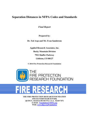
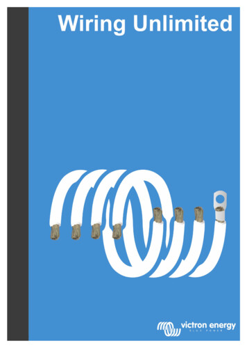
I DIVDIVOPEN TRAY(TYP ICAL)II(2} Minimum vertical seeparation requirements between any tworedundant Class 1E divisions are shown belo .BDIVI8'IVIOPEN ORENCZDSEDTRAY ORCONDUCT DIV ZITHREE OR NOREPER TIER ANDDIVarriersolidbottomor 7 DXVIzzzzzz.mMiz;SDIV Xf CONDUIT(TYP ICAL)'WOQR LESSXZAUIMATICNODIV IX DIV IXFXRE DETECTIONEXTINGUISHINGAVAILABLEfcDIV IX(3)! )"Where minimum separation re qu irembetween two racewaysrementsnof redundantn an Cl ass 1E divisions are not met, one of thefollowinq methods shall be implemented.(a)Horizontal Separation1.Open/Enclosed Race ayehInstalled ParallelhDZY DIVIIDIVI CBarrier (Typical)6
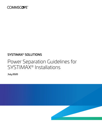
zz,,I)zi v2.Enclosed RacewaysDZVI(aIIIIIIIIIDIVInstalled ParallelIITray Covers or BarriersI'nstalled(Typical)Top' Dzv zz bzv zBottomIIIDIVII12" Minimum or Flush to Ceiling12" Minimum or Flush to Floor 1" MinimumB C DNote1- Noseparation distance is required bedivision conduits or enclosednot, physically touch.butmusttheytraysminimumtween redundant(b)Vertical Separation1.Open/Enclosed vzvRacewaysInstalled Parallelz vzvDIV ZIAzlA.zzlA
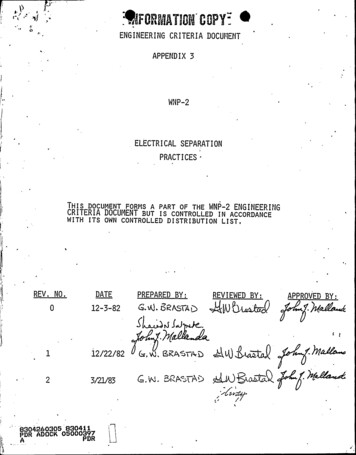
Sj1DIV,Note(4)1-DIVPara11e1II0II12" MinimumA InstalledEnclosed Raceways2.or Flush to Wall.No minimum separation distance is required between redundant division conduits or enclosedtrays but they must not physically touch.,Tray covers shall be used for all crossovers of redundant division raceway systems (where minimum verticalseparation distance i's not met), except when the bottomraceway is a conduit. The schemes shown below shall beused regardless of the voltage level of the cables in a.crossover raceway system.3W3WW DZVIDIUIDIVII1" MinDIV,IIis defined as the nominaltray width of the widest tray"W"involved.times the nominal traywidth or flush to a wall3W 3SECTION A-A
12n12NDZVDIVIDZVZII1" t4inB oiV rrSFCTION 8-RDIVIDIV1" MinIDIV IZ12"DIV ZISECTION(5)b)CMassigned to route Non-Class 1E powercables (Division A or B) shall be separated from allClass lE raceways using the separation criteria specified in a) (1) through (4) above.Open racewaysUnique Requirements1)12"For Certain General Plant AreasCable Spreading Room and Cable Chasesseparation distance between open trays of xedundant Class 1E divisions shall be one foot horizontally andthree feet vertically. The minimum separation distance between conduits and open trays of redundant Class 1Eone-inch with a barrier provided when the conduit isbelow or to the side of the open tray and three feet whenthe conduit is located above the open raceways. Where thesedistances cannot be maintained, fire barriers shall beinstalled. Automatic fire detection and suppression must beprovided or these ax'eas become General Plant Areas.The minimumdivisions's2)Periphery ofPGCCfloorraceway system is not provided in this area.this floor area shall be routed in groundedflexible conduit with 3 feet; horizontal separation main-A modularCables intained between redundant Class 1E flexible conduits. Wherethis distance cannot be maintained, one of the redundantdivisions shall be routed in rigid conduit. The redundantconduits shall not touch (a barrier may be used to physically separate the two conduits ).3)Class1EUnderground Duct SystemClass 1E equipment located remotely from the plant (e.g.,equipment located at the ultimate heat sink) is serviced bydivi-sionally separated Class lE underground duct systemsand manholes.The underground duct system for Class 1Esystems is constructed of steel encased in reinfoxcedconcrete.The minimum9hoxizontal separation between
j, \(a 3)Class 1E:Underground Duct, System (Cont'd)redundant duct banks measured from the bank edges is 18inches. Redundant duct banks do not crossover. Separationwithin manholes is provided by barriers.c)Control
Minimum separation distances for trays, conduits, cables, and cables/wires within enclosures are described below. Note that the separa-tion distances specified are to preclude internally generated fire propa-gation between redundant Class 1E divisions and do not consider effects of 'externally generated fires or pipe'reaks and missiles. 2 1 Spatial Separation Between Raceways