Transcription
ESP-LXIVM ControllerTroubleshooting Guide
For product manuals, instructional videos and FAQs,please visit: www.rainbird.com/esplxivmFor free professional support for programming andtroubleshooting, please call: 1-866-544-1406Local Rain Bird Contact InformationDistributor Mgr:Email:Phone:Area Specification MgrPublic Agency Manager:Email:Phone:Contractor Account Mgr:Email:Phone:Water Conservation Mgr:Email:Phone:2ESP-LXIVM Controller Troubleshooting GuideTable ofContents
ContentsLocal Rain Bird Contact Information.2Tools. 4Recommended.4Useful.5LX-IVM Compatible Valves. 5Controller Features. 6Front Panel.62-Wire Settings.7Diagnostics.7Cabinet Components.8Basic Programming. 9Troubleshooting Flow Charts.10Getting Started.102-Wire Mapping.11No Water Days, No Run Times, .13Shorted Paths.14Shorted Path (Manual Method).15Duplicate Address.19Flow Alarm.20Ping Valve / Sensor (Ping Test).22Field Wiring Diagnostics. 23Tools and Equipment.23Total System Milliamp Draw.233ESP-LXIVM Controller Troubleshooting GuideTable ofContents
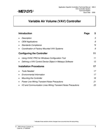
Field Wiring Issues.23Broken Wire (Open Circuit) List Not Responding.24Short Circuit.25Ground Fault.26Relay Wiring.27IVM Power Filter Connection.29Controller Diagnostics. 30IVM Interface Module. 37LED Indicators.37LED Status.38Module Status.382-Wire Path Status.38Individual Path Status.38ToolsRecommended MAXI Cable 2-Wire communications cable. Rain Bird WC20 splice kits for ALL electrical wiring connections. Rain Bird genuine Wire StripperFor video showing proper wire splice instructions and otherinstallation tips, please visit:www.rainbird.com/esplxivmB4NOTE: If installing or repairingcommunications wiring forIQ Software, do not installthe communicationscables in the same conduitas the 2-Wire path wiring.ESP-LXIVM Controller Troubleshooting GuideRain BirdWire StripperTable ofContents
Useful Milliamp MeterRecommended Model: Armada Pro 93 As-Built DrawingIf you don’t have it, make it using a cable locator LX-IVM Troubleshooting ToolsA list of ESP-LXIVM Controller Troubleshooting Videoscan be found here:https://www.rainbird.com/esplxivmLX-IVM CompatibleValvesMilliampMeterVideos for ESP-LXIVM compatible valves ,connecting and troubleshootingcan be found here: PGA Serieshttps://www.rainbird.com/products/pga-series PEB ries EFB-CP ies BPE 5NOTE: Rain Bird HV, DV, and JTV Series residential valves are notcompatible with IVM-SOL. Use only Rain Bird commercial seriesvalves for ESP-LXIVM installations:NOTE: Physical intereference on any valves can be addressedthrough “clocking” to avoid being “in-line” with IVM-SOL orremoving the component (e.g. Flow Control).ESP-LXIVM Controller Troubleshooting GuideTable ofContents
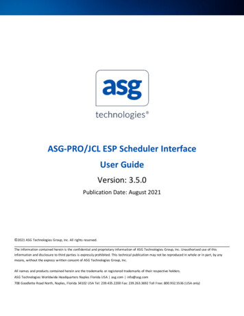
Controller FeaturesFront HTBACK BUTTONPROGRAMSELECT BUTTON6LANGUAGESELECT BUTTONINFORMATIONBUTTONESP-LXIVM Controller Troubleshooting GuideTable ofContents
2-Wire SettingsDiagnostics7ESP-LXIVM Controller Troubleshooting GuideTable ofContents
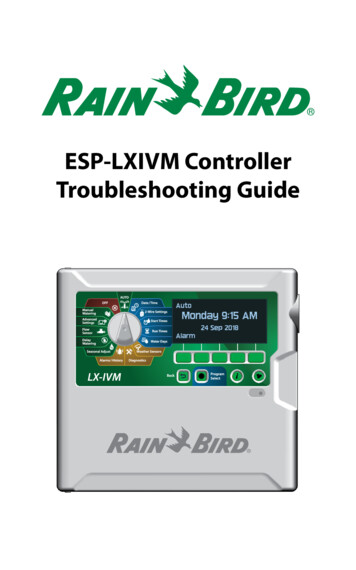
Cabinet ComponentsIVM 2-WIRE INTERFACE MODULEJUNCTIONBOXCONNECTORTRANSFORMER8ESP-LXIVM Controller Troubleshooting GuideTable ofContents
Basic ProgrammingThe ESP-LXIVM Controller has 2-Wire Settings to help get you startedand guide you through each step of the installation and hardwaresetup process.It’s most effective to use the 2-Wire Settings in the order they appear in the2-Wire Settings menu, as follows:1.2.3.4.Master ValvesWeather Sensors (if present)Station SetupFlow Sensors (if present)Installation, Programming & Operation GuideFor more information see the LX-IVM Field Device Installation Guide thatcame with the LX-IVM Controller.Or download the LX-IVM User Manual at:www.rainbird.com/esplxivm9ESP-LXIVM Controller Troubleshooting GuideTable ofContents
Troubleshooting Flow ChartsGetting StartedYESIs the LX-IVMfront panelAlarm Light on?NOTurn the dial to AUTO andpress the Alarm buttonWhat doesthe screendisplay?No Water DaysNo Run TimesNo Start TimesNo PGM will.More ExitGo topage13ShortedPathsGo topage14YESCall the ESP-LXSeriesHOTLINE at 1-866-544140610DuplicateAddressGo topage19FlowAlarmGo topage20Is the LX-IVMfront panelAlarm Lightstill on?Device NotRespondingGo topage22NOESP-LXIVM Controller Troubleshooting GuideGo topage23END - JobWell Done!Table ofContents
2-Wire Mapping2-Wire Mapping “maps” or records information on the wire-path of anyconnected IVM devices. A total of 4 wire paths are available in a LX-IVMController.BNOTE: While this information is helpful for diagnostics, not doing2-wire mapping WILL NOT affect irrigation functions. But if 2-wiremapping is NOT done, it will raise an alarm at the controller.To initiate 2-wire mapping, follow the steps below:Turn the Dial to 2-Wire Settings1. At the Advanced Station Settings screen, press the Down Arrowkey to select 2-Wire Mapping, then press Next.2. At the 2-Wire Device Mapping screen, press the and – keys toset the desired hour (from 0 to 23), then press the Right Arrowkey.Advanced Station SettingsCycle & SoakInter-Station DelaySimulStationsStation Sequencing2-Wire Mapping2-Wire Device MappingStart Device Mapping In00 : 00HH:MMNextNext3. Press the and – keys to set the desired minute (from 1 to 59),then press Next.4. At the confirmation screen, press Start to begin DeviceMapping.BNOTE: All irrigation is disrupted during the mapping process.2-Wire Device MappingStart Device Mapping InAttentionDevice Mapping willinterrupt all irrigationand could take severalminutes01 : 05HH:MMNext11ESP-LXIVM Controller Troubleshooting GuideStartTable ofContents
5. A confirmation screen shows the process is set to run.MappingMapping will beginIn 1 Hrs and 5Mins.CancelDoneThe following pictures show the List Not responding screen withoutand with 2-wire mapping done.Without 2-wire mappingLIST NOT RESPONDINGLIST NOT RESPONDINGPingPingAT 01/01/18Type#STA002STA004STA008STA01012With 2-wire mapping12 : 00 PMPath---------AT 01/01/18Type#STA002STA004STA008STA010ESP-LXIVM Controller Troubleshooting Guide12 : 00 PMPath2222Table ofContents
No Water Days, No Run Times, Turn the dial to Date/Time andensure time and date are correctTurn the dial to Start Times,Run Times and Water Daysand follow programmingdirections in the User ManualTest LX-IVM system usingManual Watering or AutoCheck the displayfor Alarms, seepage 10NOIs theLX-IVM systemworking?YESEND - JobWell Done!Troubleshooting13ESP-LXIVM Controller Troubleshooting GuideTable ofContents
Shorted PathsThe controller has automatically entered Short FindingMode to protect itself against a short on the 2-wire pathTurn the dial to Diagnostics and selectDiagnostics from the menu, then press NextPress the Down Arrow button to selectTest Shorted Paths, then press NextPress the Down Arrow button to selectthe Path (1-4) to test, then press NextBNOTE: Shorted Path willdisplay “Fault”.Press and hold the Yes buttonto energize the selected pathNote: Irrigation will be disabledTrouble Shoot in the Field using a milliamp meter.A sharp increase in current should be observedright before the Short Condition in 2-wire Path.If issue cannot be resolved using the Shorted Paths Test, referto the Shorted Path (Manual Method) on the next page.Next Page14ESP-LXIVM Controller Troubleshooting GuideTable ofContents
Shorted Path (Manual Method)Open the front panel and checkthe two indicator lights on theIVM 2-Wire Interface Module.The top indicator light shouldbe green and the bottomindicator light should bedark. This indicates that thecontroller put the module inShort Finding ModeIf there are more than one 2-wire pathsconnected, disconnect the first 2-wire pathDisconnect the second/third/fourth 2-wire pathBDid thecontroller exit ShortNOFinding Mode and areboth Indicator Lightsilluminated?NOTE: In “looped”systems, cut the loop inthe middle to create twoindependent paths.YESReconnect the Maxi-Cable to verify thecontroller goes back into Short Finding ModeNext Page15ESP-LXIVM Controller Troubleshooting GuideTable ofContents
Shorted Path (Manual Method) cont.Reconnect theMaxi-Cable to verifythe controller goesback into ShortFinding ModeRepair damagedMaxi-Cableusing MaxiCable and DRB/YconnectorsYESNOWalk the length ofthe 2-wire path andlook for signs of recentconstructions (trenching,new fence, sign, tree, etc.)Connect all2-wire paths atthe controllerand observescreenWhat doesthe displayshow?Go back toTroubleshooting,page 10Wiresdamaged, or foundrepairs of theMaxi-Cable?NOGo to an IVM device approx.50% the length of the 2-wirepath. Disconnect the IVM device2-wire splice to disconnect thesecond half of the 2-wire path.BNOTE: Instead ofphysically disconnectingthe 2-wire path, youcould instead usea clamp meter. Seepage 18.Next Page16ESP-LXIVM Controller Troubleshooting GuideTable ofContents
Shorted Path (Manual Method) cont.YESCheck thecontroller display tosee if it has exitedShort FindingModeThe problem is downstreambetween this point and theend of the 2-wire pathRe-connect the 2-wire pathand go to an IVM deviceapprox. 50% between thispoint and the end of the2-wire path. Disconnect the2-wire splice to disconnect thesecond half of the 2-wire path.BNOThe problem isupstream between thispoint and the controllerRe-connect the 2-wire pathand go to an IVM deviceapprox. 50% between thispoint and the controller.Disconnect the 2-wire spliceto disconnect the secondhalf of the 2-wire path.NOTE: Once a small section 2-wire path is identified as having anissue, use “Energize Path for Testing” and Milliamp Meter to trackfor a sharp increase in test current before the location of the short.For video instructions on Automatic ShortFinding Mode, please visit:www.rainbird.com/esplxivmNext Page17ESP-LXIVM Controller Troubleshooting GuideTable ofContents
Shorted Path (Manual Method) cont.Alternatively you can measure current draw in your system usingDiagnostics/ Diagnostics/Controller Output:BNOTE: Before measuring the amperage, calculate the approximatecurrent that the 2-wire path is consuming.System Amperage CalculationQuantity of IVM-SOLX0.67 mA Quantity of IVM-OUTX0.67 mAQuantity of other IVM-SENX6 mA Approximate total system amperage in mAIf there is a mismatch, follow a process similar to page 10 to disconnect50% of devices and redo calculation above. Continue todisconnect 50% ofdevices until you identify section of 2-wire Path with issues.BNOTE: Self-healing: Note that IVM Controller tracks the healthof the 2-wire Path to see if shorts are resolved and thenautomatically resumes irrigation. You do not need go back to theController to reset or restart.For video instructions on Locating a Shorton the Two-Wire Path, please visit:www.rainbird.com/esplxivm18ESP-LXIVM Controller Troubleshooting GuideTable ofContents
Duplicate AddressThe controller will Alarm if duplicatedevice addresses are entered for one ormore of IVM-SOL, IVM-SEN and IVM-OUT.Turn the dial to 2-Wire SettingsPress the Down Arrow button toselect Station Setup, then press NextUse the and - buttons to cycle through allthe stations. Verify that all 2-wire addressesare correct and there are no duplicates.BNOTE: Only the first twoduplicates will be shown,so you may need to repeatthis process until all ofthe duplicates have beenaddressed.Test LX-IVM system usingManual Run or Auto RunCheck the displayfor Alarms,see page 10Troubleshooting19NOIs theLX-IVM systemworking?YESESP-LXIVM Controller Troubleshooting GuideEND - JobWell Done!Table ofContents
Flow AlarmAlarms are issued when flow conditionsexceed your High or Low Flow settings.CONTINUEDTurn the dial to Alarms/HistoryFROM NEXTPAGE (21)Press the Down Arrow button toselect Flow Alarms, then press NextPress the Down Arrow button to selectStation Flow Alarms, then press NextTroubleshoot and fix anystation that shows an alarmGo Back and select FloZone Flow AlarmsTroubleshoot and fix anyFloZone that shows an alarmNext Page20ESP-LXIVM Controller Troubleshooting GuideTable ofContents
Flow Alarms cont.After fixing any station or FloZone issues,go Back and select Clear Flow AlarmsRun all zones manuallyCheck the Alarms screen to see if previous alarm clearedNOAlarm iscleared onthe displayYESEND - JobWell Done!GO BACKTO PREVIOUSPAGE (20)21ESP-LXIVM Controller Troubleshooting GuideTable ofContents
Ping Valve / Sensor (Ping Test)Assumption: A valve or sensor may not be workingTurn the dial to DiagnosticsPress the Down Arrow button to selectPing Valve/Sensor then press NextPress the and - buttons to select the type of device to test(Station, Master Valve, Flow Sensor, Weather Sensor, etc.)Press the button to select the numberof the device to test, then press PingThe controller will ping the selected device andreport a voltage reading if the device respondsInterpreting Ping ResultsIf the device does not respond verify the address and check the wiresplices. The voltage reading is a measurement of the charge of thedevice capacitors.If the voltage is low, wait a minute then ping again.If the voltage is still low (below 23 volts), disconnect the devicefrom the 2-wire path and connect directly to an unused wire path atController and repeat Ping Test. If the voltage is fine, the issue is with2-wire path / splicing. If the voltage is still bad, replace the device.22ESP-LXIVM Controller Troubleshooting GuideTable ofContents
Field Wiring DiagnosticsThe ESP-LXIVM Controller includes multiple diagnostic functions to helpyou determine the cause of a field wiring issue.Tools and Equipment An accurate “as-built” showing wire path and 2-wire device locations,the number and type of the 2-wire devices on each wire path, and2-wire addresses Filled out LX-IVM Controller Programming Guide with 2-wireaddresses and station/MV/sensor assignments A Volt/Ohm Meter (multi-meter) capable of reading 0 to 50 volts AC/DC and resistance from 0 to 1,000,000 Ohms A Clamp Meter for measuring AC current with a precision of 1.0 mA(milliamp) Wire tracing and fault finding equipment Spare system components and tools including: spare IVM-SOL, IVMSEN device, WC20 Splice Kits and wire strippersTotal System Milliamp DrawBefore troubleshooting a field wiring issue, calculate the expected totalsystem draw in milliamp (mA). This value can be compared to actualreadings during troubleshooting. Each IVM-SOL, IVM-OUT draws 0.67mA IVM-SEN draws 6 mA Add up the total devices of each type for each wire path andcalculate the wire path mA draw Add the mA for each wire path together for the total system mAdrawField Wiring IssuesField wiring issues are typically caused by a broken wire, a short circuit or aground fault in the 2-wire path. Refer to the section that best describes theobserved symptoms to troubleshoot. Broken Wire (Open Circuit) Short Circuit Ground Fault23Next PageESP-LXIVM Controller Troubleshooting GuideTable ofContents
BBNOTE: A majority of field wiring issues are caused by poor wiresplices. Use only WC20 Splice Kits. All splices should be made insplice boxes.NOTE: If the 2-wire path is Looped, disconnect the loop half wayout before troubleshooting.Broken Wire (Open Circuit) List Not RespondingIf there is a broken wire causing an open circuit in the 2-wire path, youwill notice one or more stations are not running even though they areprogrammed to operate. If the system is using flow sensing, you willreceive a low (zero) flow alarm for each disconnected 2-wire station.Controller Diagnostics1. Turn the dial to Test All Stations / Check System. Select 2-WireDiagnostics.2. Select the List Not Responding. The results will indicate thatone or more devices have an open circuit and you will beprompted to Check Wiring. Go to the location of the 2-wiredevices that are not responding and check all wire splices.2-Wire Path Diagnostics1. Note the “List Not Responding” displays and correspondingwire paths. If you notice that all the 2-wire devices that are notresponding are in a single leg of the 2-wire path, the opencircuit exists between the last working 2-wire device andthe first non-working 2-wire device. Check the splices at thatlocation first. Also look for signs of recent construction/diggingbetween the working and non-working 2-wire devices.BNOTE: If 2-Wire mapping is not done, the wire path column willnot include any information.2. Turn the controller dial to 2-Wire Diagnostics; Select ShortFinding; Turn Short Finding Mode On. Use a Clamp Meter tomeasure the Amp Draw of the 2-wire path cable conductors atthe last working device and the first non-working device. Noteany discrepancies in the readings. You must know the numberand type of each device downstream to know what the mAreading up should be reading (see the Total System MilliampDraw section for more information).24ESP-LXIVM Controller Troubleshooting GuideTable ofContents
Short CircuitIf there is a short circuit (can be caused by crossed red and black wires)in the 2-wire path, the controller Alarm light will be illuminated and thealarm will inform you the controller has switched to Short Finding Mode.You must fix the short circuit before the controller will switch back tonormal irrigation mode.2-Wire Path Diagnostics1. Disconnect each 2-wire path cable one at a time from thecontroller IVM 2-Wire Interface Module until the controller exitsShort Finding Mode. Reconnect that 2-wire path cable, and ifthe Short Finding Mode returns you know the short is on thatleg of the 2-Wire path.2. Refer to the as-built to see the location of the 2-wire path. Walkthe route of the 2-wire path cable and check for signs of recentconstruction/digging.3. Find a device location about half-way down the 2-wire pathcable. Disconnect the splices. See if the controller is still inShort Finding Mode. If the Short Finding Mode has cleared, theproblem is downstream of this location. If the controller is stillin Short Finding Mode, the problem is between this locationand the controller. Keep disconnecting segments of the 2-wirepath until you isolate the problem.4. Use a Clamp Meter to measure the Amp Draw of the 2-wirepath cable conductors at the last working device and the firstnon-working device. Note any discrepancy in the readings. Youmust know the number and type of each device downstream toknow what the mA reading up should be reading (see the TotalSystem Milliamp Draw section for more information).5. The problem may be caused by a device that was damaged bya lightning power surge. The controller will exit Short FindingMode when the damaged device is disconnected from the2-wire path.25ESP-LXIVM Controller Troubleshooting GuideTable ofContents
Ground FaultA ground (earth) fault can be caused when a 2-wire path conductoris leaking to ground, possibly due to a bad wire splice, or a nicked ordamaged cable. This issue may come and go depending on the soilmoisture level. When the soil is very wet the problem will be worse thanwhen the soil is dry.Controller Diagnostics1. Turn dial to Diagnostics / Diagnostics / Control Output.2. Select Controller. Note the Milliamp (mA) reading. The mAreading will be higher than normal when current is leakingto ground. You must know the number and type of eachdevice in the system to know what the mA reading should bereading (see the Total System Milliamp Draw section for moreinformation).3. Disconnect each 2-wire path cable one at a time from thecontroller IVM 2-Wire Interface Module. Recheck the ControlOutput to isolate which segment of the 2-wire path has theground fault.4. Find a device location about half-way down the 2-wire pathcable. Disconnect the splices.5. Check the Control Output to see if the ground fault has beenisolated. If the Control Output is normal, the problem isdownstream of this location. If the Control Output still showsthe ground fault, the problem is between this location and thecontroller. Keep disconnecting segments of the 2-wire pathuntil you isolate the problem.2-Wire Path Diagnostics1. Turn the controller dial to Diagnostics / Diagnostics / TestShorted Path.2. Use a Clamp Meter to measure the Amp Draw of the 2-wirepath cable conductors at various splice locations. Note anydiscrepancy in the readings. You must know the number andtype of each device downstream to know what the mA readingup should be reading (see the Total System Milliamp Drawsection for more information).26ESP-LXIVM Controller Troubleshooting GuideTable ofContents
Relay WiringFor valves without compatible latching solenoids.IVM-SOL device can be used to connect any Rain Bird Commercial Valveto the LX-IVM Controller. For Non-Rain Bird Valve, use IVM-OUT device inconjunction with a compatible DC latching solenoid to connect to a LX-IVMcontroller. In the event, a compatible DC latching solenoid is not available,you can use the Rain Bird Pump Start Relay with following modifications topower the AC Solenoid.1. Connect 110V relay to the or - 24VAC terminals at thecontroller’s IVM 2-wire Interface Module.BNOTE: Do not connect 2-wire path to the 110V relay terminals.2. Unplug PSR relay coil wires and output to AC Solenoid.BNOTE: Feed the solenoid wires through bottom of the PSRenclosure.ABC27ESP-LXIVM Controller Troubleshooting GuideTable ofContents
3. Connect the red and white IVM-OUT wire to the red wire of theDC Latching Relay. Connect the black and white IVM-OUT wire tothe black wire of the DC Latching Relay.4. Connect the red IVM-OUT wire to the red wire on the 2-Wirepath. Then connect the black IVM-OUT wire to the black wire onthe 2-Wire path.Input Powerfrom 24VACOut Terminalat ControllerAC SolenoidModel Nos.PSR110-IVMand PSR220-IVMDIVM-OUTCAllow 3 ft. (1 m)Extra CableLength28AC SolenoidESP-LXIVM Controller Troubleshooting GuideTable ofContents
IVM Power Filter ConnectionElectrical Noise in the input power can cause undesirable behavior of theLXIVM Controllers. Sources of Electrical Noise include VFD Pump and otherElectrical Equipment.Rain Bird recommends the GSP-IVM Filter to filter the noise from the inputpower and ensure normal operation of the Controller. Symptoms can includeinconsistent operation of the stations (stations not running as programmed)and inability read flow from a compatible flow sensor.Rain Bird recommends the following modification to the controller to “filterout” the noise and ensuring normal operations of the Controller.Choke: SchaffnerP/N: RD5122-6-9M6Terminal Blockon LX-IVM(24VAC IN)ORANGEYELLOWBLUEORANGEYELLOWBROWNGROUNDGREEN or GREEN YEL.(not connected)LX-IVM Transformer(26.5VAC Out)BCapacitor, Kemet P/N:C274ACF5100SA0JNOTE: IVM Filter Kit can be sourced from Rain Bird GSP via theonline services store (link er.html29ESP-LXIVM Controller Troubleshooting GuideTable ofContents
Controller DiagnosticsUse this table to troubleshoot issues using the built-in diagnostic featuresof the ESP-LXIVM controller.CategoryIssuePotential CauseSolutionControllerAlarmsRed alarmlight on thecontrollerfront panel isilluminated.The controller isreporting an alarmcondition.Turn dial to Auto, press the Alarm button,review the alarm conditions, and addressthe issue(s).ControllerThe IVM 2-Wirealarm; NoInterface Module2-Wire Module. is not properlyattached to thecontroller moduleslots.Controlleralarm; 2-Wirepath Off.Check the upper status light on the IVM2-Wire Interface Module. It should be solidgreen if it is properly connected to thecontroller. Remove and reinstall the modulemaking sure it is fully seated in the moduleslots.Someone hasTurn dial to Off, press the 2-Wire Path button,manually turned the and turn the 2-wire path On.2-wire path Off.ControllerDuplicate DeviceNote the duplicate Device Addresses postedalarm;addresses have been in the alarm screen, verify and enter theDuplicateentered.correct Device addresses.Device Address.Controlleralarm; ShortFinding Mode.2-wire path isshorted and thecontroller hasautomaticallyswitched to theShort Finding Mode.The lower leftstatus light on thecontroller is dark.Disconnect the 2-wire cables from the IVM2-Wire Interface Module one at a time untilthe alarm condition clears. The lower leftstatus light on the controller will alternatebetween red and green when the wire pathwith the short is removed.Trace the path of this 2-wire cable and lookfor source of issue (disturbed soil, new tree orfence post, etc).Disconnect the 2-wire cable halfway betweenthe controller and end of cable and check tosee if the alarm clears to help identify shortlocation on the cable.Use a volt/ohm and clamp meter to identifywhich devices are receiving power.Fix the short and check that the alarm iscleared.Controlleralarm; NoDeviceAddresses.30Device addresseshave not beenentered for anystations.Turn dial to 2-Wire Settings / Station Setup.Enter the address (see label on each Device)for each station. Addresses are also requiredfor Master Valves, Weather Sensors and FlowSensor.ESP-LXIVM Controller Troubleshooting GuideTable ofContents
CategoryControllerAlarmsIssueControlleralarm; ZeroLearnedFlow.Potential CauseThe Learn FlowUtility has recordeda zero (0) flow ratefor one or morestation.SolutionTurn dial to Flow Sensor / Set Flow Rates /View Flow Rates / View Station Rates. Check forstations that have a 0 flow rate and are labeledLearned. If all stations have learned a 0 flow check flowsensor/ input connections, Flow Sensor configuration, FloZone assignments, etc. If only one or a few stations have learned a0 flow rate check the valve operation (flowcontrol stem position, solenoid, wiring, etc.). If just small flow rate valves/stations (like dripzones) have learned a 0 flow rate the flowsensor may be too large for the lower flowrates. Check the product technical specs for theminimum flow rate of the flow sensor.ControllerFloWatch (flowalarm; Flow sensing utility) hasAlarm.detected a high orlow flow condition.Turn dial to Alarms / History / Flow Alarms,and review the posted Station and/or FloZone(mainline) flow alarms. Note the station(s) orFloZone(s) that were identified. If you configuredFloWatch to Diagnose & Eliminate or Alarm &Shut Down, the problem station(s) or FloZone(s)will be quarantined. Clear the Flow Alarms andtest the system. Station flow alarms – Manually turn on thestation. Turn dial to Flow Sensor / View CurrentFlow. The current and expected flow rateswill be listed. Check the valve & sprinklers toidentify the issue and correct it. If sprinklers ornozzles have been replaced, relearn the stationflow rate. FloZone alarms - Manually start a program.Turn dial to Flow Sensor, View Current Flow. Thecurrent and expected flow rates will be listed.Check the water source(s) and mainline toidentify the issues and correct it. If FloZone high flow alarms are being triggeredby manual watering (QCV, manually bleedingvalves, etc.) consider using the MV WaterWindow located under the Manual Wateringdial position. Configure window open andclose times, days of the week, MV(s) you wantopen, and theexpected additional flow rate to allow for themanual watering.31ESP-LXIVM Controller Troubleshooting GuideTable ofContents
CategoryControllerAlarmsIssuePotential CauseSolutionController alarm; A non-compatible Remove any recently added modules, one at aInvalid Modulemodule has been time, until the alarm condition clears.Config.inserted into oneof the controller ESP-LXME/-LXMEF Controller 4-, 8-, &module slots.12-Station Modules, FSM Flow SmartModules, M50 and SM75 Modules are notcompatible.Controller alarm; IncompleteNo PGM will Auto programming.Run.ControllerAlarm; NoPower – IrrigationFunctions areDisabled.2-Wire Path CommunicationIssueswith 2-wiredevices isintermittent.Turn dial to Diagnostics / Confirm Programs/ Program Summary. Missing progr
IQ Software, do not install the communications cables in the same conduit as the 2-Wire path wiring. . Ping STA0 08 ---STA0 10 ---LIST NOT RESPONDING AT 01/01/18 Type STA STA 002 004 # 2 2 Path 12 : 00 PM Ping STA0 08 2 . tree, etc.) Wires damaged, or found repairs of the Maxi-Cable? Repair damaged Maxi-Cable using Maxi Cable and DRB/Y .