Transcription
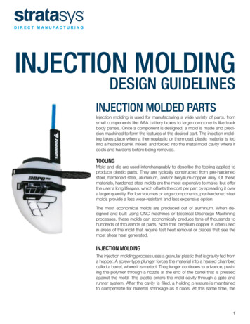
INJECTION MOLDINGDESIGN GUIDELINESINJECTION MOLDED PARTSInjection molding is used for manufacturing a wide variety of parts, fromsmall components like AAA battery boxes to large components like truckbody panels. Once a component is designed, a mold is made and precision machined to form the features of the desired part. The injection molding takes place when a thermoplastic or thermoset plastic material is fedinto a heated barrel, mixed, and forced into the metal mold cavity where itcools and hardens before being removed.TOOLINGMold and die are used interchangeably to describe the tooling applied toproduce plastic parts. They are typically constructed from pre-hardenedsteel, hardened steel, aluminum, and/or beryllium-copper alloy. Of thesematerials, hardened steel molds are the most expensive to make, but offerthe user a long lifespan, which offsets the cost per part by spreading it overa larger quantity. For low volumes or large components, pre-hardened steelmolds provide a less wear-resistant and less expensive option.The most economical molds are produced out of aluminum. When designed and built using CNC machines or Electrical Discharge Machiningprocesses, these molds can economically produce tens of thousands tohundreds of thousands of parts. Note that beryllium copper is often usedin areas of the mold that require fast heat removal or places that see themost shear heat generated.INJECTION MOLDINGThe injection molding process uses a granular plastic that is gravity fed froma hopper. A screw-type plunger forces the material into a heated chamber,called a barrel, where it is melted. The plunger continues to advance, pushing the polymer through a nozzle at the end of the barrel that is pressedagainst the mold. The plastic enters the mold cavity through a gate andrunner system. After the cavity is filled, a holding pressure is maintainedto compensate for material shrinkage as it cools. At this same time, the1
screw turns so that the next shot is moved into a readyposition, and the barrel retracts as the next shot is heated.Because the mold is kept cold, the plastic solidifies soonafter the mold is filled. Once the part inside the mold coolscompletely, the mold opens, and the part is ejected. Thenext injection molding cycle starts the moment the moldcloses and the polymer is injected into the mold cavity.INJECTION MOLDING MATERIALSMaterials Selection: Many types of thermoplastic materials are available. Selection depends on the specificapplication. The chart below shows some of the mostcommon materials being used.INJECTION MOLDING ENGINEEREDTHERMOPLASTIC MATERIALSNylonsPolyphenylene SulfidePPSPolycarbonatesPolyehter ropolymersPolypropylenesPolyether ImidePEIPolyethylenesPolyphenylene OxidePPOAcrylonitrile omersPolyphthalamidePPAWALL SECTIONCONSIDERATIONSWALL THICKNESSCost savings are highest when components have amini-mum wall thickness, as long as that thickness iscon-sistent with the part’s function and meets all moldfilling considerations. As would be expected, parts coolfaster with thin wall thicknesses, which means thatcycle times are shorter, resulting in more parts per hour.Further, thin parts weigh less, using less plastic per part.On average, the wall thickness of an injection moldedpart ranges from 2mm to 4mm (.080 inch to .160inch). Thin wall injection molding can produce wallsas thin as .05mm (.020 inch).UNIFORM WALLSParts with walls of uniform thickness allow the moldcavity to fill more easily since the molten plasticdoes not have to be forced through varyingrestrictions as it fills.If the walls are not uniform the thin section coolsfirst, then as the thick section cools and shrinks itbuilds stresses near the boundary area between thetwo. Be-cause the thin section has already hardened,it doesn’t yield. As the thick section yields, it leads towarping or twisting of the part, which, if severeenough, can cause cracks.Figure 1:Uniform wall thickness can reduce or eliminate warping2STRATASYSDIRECT.COM 888-311-1017
What if you cannot have uniform walls(due to design limitations)?If design limitations make it impossible to have uniformwall thicknesses, the change in thickness should be asgradual as possible.VOIDS AND SHRINKAGETroublesome shrinkage problems can be caused by theintersection of walls that are not uniform in wall thickness. Examples might include ribs, bosses, or any otherprojection of the nominal wall. Since thicker walls solidifyslower, the area they are attached to at the nominal wallwill shrink as the projection shrinks. This can result ina sunken area in the nominal wall. Such shrinkage canbe minimized if a rib thickness is maintained to between50 and 60 percent of the walls they are attached to. Tofurther our example, bosses located into a corner willproduce very thick walls, causing sink, unless isolated asin the illustration below.Figure 2: Transition of wall thicknessCoring is a method where plastic is removed from thethick area, which helps to keep wall sections uniform,eliminating the problem altogether.Figure 5: Boss design to eliminate sinksWARPAGEFigure 3: Coring to eliminate sinksThe dynamic of thin and thick sections and their coolingtimes creates warping as well. As would be expected, asa thick section cools it shrinks, and the material for theshrinkage comes from the unsolidified areas causing thepart to warp.Gussets are support structures that can be designedinto the part to reduce the possibility of warping.Other causes for warping might include the molding process conditions, injection pressures, cooling rates, packingproblems, and mold temperatures. Resin manufacturers’process guidelines should be followed for best results.Figure 4: Gusseting to reduce warpingFigure 6: Warpage caused by non-uniform wall thickness3
BOSSESBosses are used to facilitate the registration of matingparts, for attaching fasteners such as screws, or for accepting threaded inserts.Figure 7: Boss design guidelinesWall thicknesses for bosses should be less than 60 percent of the nominal wall to minimize sinking. However,if the boss is not in a visible area, then the wall thickness can be increased to allow for increased stressesimposed by self-tapping screws.RIBSRibs are used in a design to increase the bending stiffness of a part without adding thickness. Ribs increasethe moment of inertia, which increases the bendingstiffness.Bending Stiffness E (young’s Modulus) x I (Momentof Inertia)Rib thickness should be less than wall thickness to minimize sinking effects. The recommended rib thicknessshould not exceed 60 percent of the nominal thickness.Plus, the rib should be attached with corner radii asgenerous as possible.Figure 8: Boss strengthening techniqueThe base radius should be a minimum of 0.25 X thickness. Bosses can be strengthened by incorporating gussets at the base or by using connecting ribs attaching tonearby walls.Figure 9: Proper rib design reduces sinking4STRATASYSDIRECT.COM 888-311-1017
RIB INTERSECTIONSBecause the thickness of the material will be greater atthe rib intersections, coring or another means of material removal should be employed to avoid excessivesinking from occurring on the opposite side.Figure 12: Rib/ load orientation affects part stiffness;Draft angles for ribs should be a minimum of 0.25 to 0.5degree of draft per sideFigure 10: Coring at rib intersectionsRIB GUILDELINESThe height of a rib should be limited to less than threetimes its thickness. It is better to use multiple ribs toincrease bending stiffness than to use one very tall rib.DRAFT AND TEXTUREMold drafts facilitate part removal from the mold. Thedraft must be in an offset angle that is parallel to themold opening and closing. The ideal draft angle fora given part depends on the depth of the part in themold and its required end-use function.Figure 12: Draft AngleFigure 11: Design guidelines for ribsRIB/LOAD AFFECT ON STIFFNESSA rib is oriented in such a way as to provide maximumbending stiffness to the part. By paying attention to partgeometry, designers must be conscious of the orientation of the rib to the bending load or there will be noincrease in stiffness.Allowing for as much draft as possible will permit partsto release from the mold easily. Typically, one to twodegrees of drafts with an additional 1.5 degrees per0.25mm depth of texture is enough to do the trick.The mold part line will need to be located in a way thatsplits the draft in order to minimize it. If no draft is acceptable due to design considerations, a side actionmold may be required.5
TEXTURES AND LETTERINGWhether to incorporate identifying information or to include as an aesthetic addition, textures and lettering canbe included onto mold surfaces for the end user or factory purposes. Texturing may also hide surface defectssuch as knit lines and other imperfections. The depth ofthe texture or letters is somewhat limited, and extra draftneeds to be provided to allow for part removal from themold without dragging or marring the part.Draft for texturing is somewhat dependent on the partdesign and specific texture desired. As a general guideline, 1.5 min. per 0.025mm (0.001 inch) depth of texture needs to be allowed for in addition to the normaldraft. Usually for general office equipment such as laptop computers a texture depth of 0.025 mm (0.001 inch)is used and the minimum draft recommended is 1.5 .More may be needed for heavier textured surfaces suchas leather (with a depth of 0.125 mm/0.005 inch) thatrequires a minimum draft of 7.5 .Figure 13: Stress Concentration Factor, KAt corners, the suggested inside radius is 0.5 times thematerial thickness and the outside radius is 1.5 timesthe material thickness. A bigger radius should be usedif part design allows.SHARP CORNERSSharp corners greatly increase stress concentration,which, when high enough, can lead to part failure.Sharp corners often come about in non-obviousplaces, such as a boss attached to a surface, or astrengthening rib. The radius of sharp corners needsto be watched closely because the stress concentration factor varies with radius for a given thickness. Asillustrated in the chart to the left, the stress concentration factor is high for R/T values less than 0.5, butfor R/T values over 0.5 the concentration lowers. Thestress concentration factor is a multiplier that greatlyincreases stress. It is recommended that an insideradius be a minimum of one times the thickness.In addition to reducing stresses, the fillet r adius p rovides a streamlined flow path for the molten plastic, resulting in an easier fill of the mold.6STRATASYSDIRECT.COM 888-311-1017Figure 14: Radius RecommendationINSERTSInserts used in plastic parts provide a place for fastenerssuch as machine screws. The advantage of using insertsis that they are often made of brass and are robust. Theyallow for a great many cycles of assembly and disassembly. Inserts are installed in injection molded parts using one of the following methods:
LIVING HINGESFigure 15: Threaded InsertULTRASONIC INSERTIONUltrasonic insertion is when an insert is “vibrated” intoplace by using an ultrasonic transducer called the “horn”that is mounted into the ultrasonic device. For optimumperformance, the horn is specially designed for each application. Ultrasonic energy is converted to thermal energy by the vibrating action, which allows the insert to bemelted into the hole. This type of insertion can be donerapidly, with short cycle times, and low residual stresses.Good melt flow characteristics for the plastic is necessary for the process to be successful.THERMAL INSERTIONThis method uses a heated tool, like a soldering iron,to first heat the insert until it melts the plastic, and thenpresses the insert into place. As the plastic cools itshrinks around the insert, capturing it. The advantageof this method is that the special tooling is inexpensiveand simple to use. Care does need to be taken not tooverheat the insert or plastic, which could result in a nonsecure fit and degradation of the plastic.Living hinges are thin sections of plastic that connect twosegments of a part to keep them together and allow thepart to “hinge” open and closed. Typically these hingesare incorporated in containers that are used in high volume applications such as toolboxes and CD cases.Figure 16: Box with Living HingeMaterials used in molding living hinges must be veryflexible, such as polypropylene or polyethylene. A welldesigned living hinge typically flexes more than a millioncycles without failure.MOLDED-INTo mold inserts into place during the molding cycle, corepins are used to hold the inserts. The injected plasticcompletely encases the insert, which provides excellentretention. This process may slow the molding cycle because inserts have to be hand loaded, but it also eliminates secondary operations such as the ultrasonic andthermal insertion methods. Finally, for high volume production runs, an automatic tool can load the inserts butthis increases the complexity and cost of the mold.Figure 17:Living Hinge Design for Polypropylene and Polyethylene7
GAS ASSIST MOLDINGOVERMOLDINGThis process is used to hollow out thick sections of apart where coring is not an option and sink is not acceptable. Gas assist molding can be applied to almost anythermoplastic, and most conventional molding machinescan be adapted for gas assist molding.The overmolding process is when a flexible material ismolded onto a more rigid material called a substrate. Ifproperly selected, the overmolded (flexible material) willform a strong bond with the substrate. Bonding agentsare no longer required to achieve optimum bond between the substrate and overmold.INSERT MOLDINGThe most widely used overmolding process is insertmolding. This is where a pre-molded substrate is placedinto a mold and the flexible material is shot directly overit. The advantage of this process is that conventional,single shot injection molding machines can be used.TWO SHOT MOLDINGThis is a multi-material overmolding process that requiresa special injection molding machine that incorporatestwo or more barrels. This allows two or more materialsto be shot into the same mold during the same moldingcycle. The two shot molding is usually associated withhigh volume production of greater than 250,000 cycles.Figure 18: Gas Assist Molding8STRATASYSDIRECT.COM 888-311-1017Copyright 2015 Stratasys Direct, Inc. All rights reserved.Proprietary information do not distribute without prior consentfrom Stratasys Direct Manufacturing.
INJECTION MOLDING. DESIGN GUIDELINES. INJECTION MOLDED PARTS. Injection molding is used for manufacturing a wide variety of parts, from small components like AAA battery boxes to large components like truck body panels. Once a component is designed, a mold is made and preci-sion machined to f