Transcription
Computer Aided Machine DrawingLAB MANUAL(18ME36A)DEPARTMENT OF MECHANICAL ENGINEERINGBAPUJI INSTITUTE OF ENGINEERING AND TECHNOLOGYDAVANGERE- 577 004
DEPARTMENT OFMECHANICAL ENGINEERINGCOMPUTER AIDED MACHINE DRAWING(18ME36A/46A)As per VTU Syllabus CBCS scheme for III SemesterName: USN: Semester: Batch No. .Mohan T RFaculty InchargeMallikarjuna V KInstructorBAPUJI INSTITUTE OF ENGINEERING AND TECHNOLOGYDAVANGERE- 577 004
VISION OF THE INSTITUTETo be center of excellence recognized nationally and internationally, indistinctive areas of engineering education and research, based on a culture ofinnovation and invention.MISSION OF THE INSTITUTEBIET contributes to the growth and development of its students by impartinga broad based engineering education and empowering them to be successfulin their chosen field by inculcating in them positive approach, leadershipqualities and ethical values.VISION OF THE DEPARTMENTThe department endeavors to be a center of excellence, to provide qualityeducation leading the students to become professional mechanical engineerswith ethics, contributing to the society through research, innovation,entrepreneurial and leadership qualities.MISSION OF THE DEPARTMENT1. To impart quality technical education through effective teaching- learningprocess leading to development of professional skills and attitude to excel inMechanical Engineering.2. To interact with institutes of repute, to enhance academic and researchactivities.3.To inculcate creative thinking abilities among students and developentrepreneurial skills.4. To imbibe ethical, environmental friendly and moral values amongststudents through broad based education.
PROGRAM EDUCATIONAL OBJECTIVES (PEO’S)1. Enable to understand mechanical engineering systems those aretechnically viable, economically feasible and socially acceptable toenhance quality of life.2. Apply modern tools and techniques to solve problems in mechanical andallied engineering streams.3. Communicate effectively using innovative tools, to demonstrateleadership and entrepreneurial skills.4. Be a professional having ethical attitude with multidisciplinaryapproach to achieve self and organizational goals.5. Utilize the best academic environment to create opportunity to cultivatelifelong learning skills needed to succeed in profession.PROGRAM SPECIFIC OUTCOMES (PSO’S)PS01:-Apply the acquired knowledge in design, thermal, manufacturingand interdisciplinary areas for solving industry and socially relevantproblems.PS02:-To enhance the abilities of students by imparting knowledge inemerging technologies to make them confident mechanical engineers.
COMPUTER AIDED MACHINE DRAWING (18ME36)B. E. MECHANICAL ENGINEERINGChoice Based Credit System (CBCS) and Outcome Based Education (OBE)SEMESTER - IIICOMPUTER AIDED MACHINE DRAWINGCourse Code18ME36A/46ACIE Marks40Teaching Hours/Week (L:T:P)1:4:0SEE Marks60Credits03Exam Hours03Course Learning Objectives: To acquire the knowledge of CAD software and its features. To familiarize the students with Indian Standards on drawing practices. To impart knowledge of thread forms, fasteners, keys, joints and couplings. To make the students understand and interpret drawings of machine components leading topreparation ofAssembly drawings manually and using CAD packages. To acquire the knowledge of limits, tolerance and fits and indicate them on machine drawings.Part AIntroduction: Review of graphic interface of the software. Review of basic sketching commands andnavigational commands. Starting a new drawing sheet. Sheet sizes. Naming a drawing, Drawing units,grid and snap. Conversion of pictorial views into orthographic projections of simple machine parts (withand without section). Hidden line conventions. Precedence of lines.Sections of Solids: Sections of Pyramids, Prisms, Cubes, Tetrahedrons, Cones and Cylinders restingonly on their bases (No problems on axis inclinations, spheres and hollow solids). True shape of sections.Conversion of pictorial views into orthographic projections of simple machine parts. Hidden lineconventions. Precedence of lines. Conversion of pictorial views into orthographic projections of simplemachine parts (with section planes indicated on the part).Thread Forms: Thread terminology, sectional views of threads. ISO Metric (Internal & External), BSW(Internal & External) square and Acme. Sellers thread, American Standard thread.Fasteners: Hexagonal headed bolt and nut with washer (assembly), square headed bolt and nut withwasher (assembly) simple assembly using stud bolts with nut and lock nut. Flanged nut, slotted nut, taperand split pin for locking, counter sunk head screw, grub screw, Allen screw.Part BKeys: Parallel key, Taper key, Feather key, Gib-head key and Woodruff key.Joints: Cotter joint (socket and spigot), knuckle joint (pin joint) for two rods.Couplings: Split Muff coupling, Protected type flanged coupling, pin (bush) type flexible coupling, anduniversal coupling (Hooks' Joint)Part CLimits, Fits and Tolerances: Introduction, Fundamental tolerances, Deviations, Methods of placing limitdimensions, machining symbols, types of fits with symbols and applications, geometrical tolerances ondrawings. Standards followed in industry.Assembly Drawings: (Part drawings shall be given)1. Plummer block (Pedestal Bearing)2. Lever Safety Valve3. I.C. Engine connecting rod4. Screw jack (Bottle type)5. Tailstock of lathe6. Machine vice7. Tool head of shaperDepartment of Mechanical Engineering, BIET., Davanagere 57004.
COMPUTER AIDED MACHINE DRAWING (18ME36)Course Outcomes:At the end of the course, the student will be able to:CO1: Identify the national and international standards pertaining to machine drawing.CO2: Understand the importance of the linking functional and visualization aspects in the preparationof the part drawingsCO3: Apply limits and tolerances to assemblies and choose appropriate fits for given assemblies.CO4: Interpret the Machining and surface finish symbols on the component drawings.CO5: Preparation of the part or assembly drawings as per the conventions.Scheme of Examination: Two questions to be set from each Part A, part B and Part C. Student has to answer onequestion eachfrom Part A and Part B for 25 marks each and one question from Part C for50 marks.INSTRUCTION FOR COMPUTER AIDED MACHINE DRAWING (15ME36A/46A)EXAMINATION1. No restriction of timing for sketching/ computerization of solutions. The total duration is 3 hours.2. It is desirable to do sketching of all the solutions before computerization.3. Drawing instruments may be used for sketching.4. For Part A and Part B, 2D drafting environment should be used.5. For Part C, 3D environment should be used for parts and assembly, and extract 2D viewsof assembly.SlNoTextbooksTitle of the BookName of the Author/sName of the PublisherEditionand Year1Machine DrawingK.R. Gopala KrishnaSubhash Publication20052Machine DrawingN.D.Bhat&V.M.PanchalCharoratar publishinghouse2005Reference Books1A Text Book of ComputerAided Machine DrawingS. Trymbaka MurthyCBS Publishers, NewDelhi20072Engineering drawingP.S.GillS K Kataria and Sons20133Machine DrawingN. Siddeshwar, P.Kanniah, V.V.S. SastriTata McGraw Hill2006Department of Mechanical Engineering, BIET., Davanagere 57004.
DO’s1. Computer lab users must sign in and out of the lab2. Wearing Uniform in the lab is compulsory.3. Take care of your eyes, by relaxing few minutes while using computer4. Adjust the chair settings to adopt your body for the proper height and lumbar support.5. Proper code of conduct and ethics must be followed in the lab.6. Operate the computer system and other hardware devices with careDONT’s1. Software may be installed by the Computer Lab staff only. Do not install any software onyour own. Unnecessary files found in the system will be removed by the concerned staff.2. Activities in computer Lab that are considered to be abusive to the software, hardwareand/or personnel will be suitably penalized3. Do not modify any software or files. Do not overwrite the operating system or any otherparameters in the computer system4. Copying software without appropriate authorization is not permitted.5. External devices like pen drive, CD’s should be avoided so that computer systems are freefrom virus.
CONTENTSSl. No.1.2.PART ANAME OF UNITSPAGE No.ORTHOGRAPHIC PROJECTIONS1-3THREAD 16-19ASSEMBLY DRAWINGS20-345.PART B6.7.PART CDepartment of Mechanical Engineering, BIET., Davanagere 57004.COMPUTER AIDED MACHINE DRAWING (18ME36)6-11
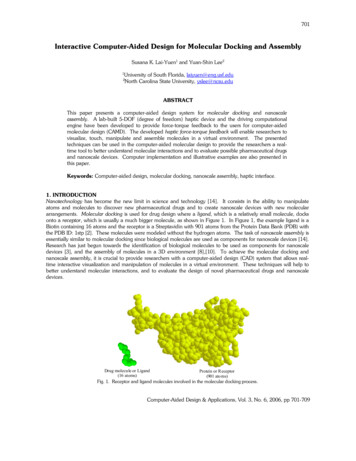
CAMD LAB LAYOUTDepartment of Mechanical Engineering, BIET., Davanagere 57004.COMPUTER AIDED MACHINE DRAWING (18ME36)
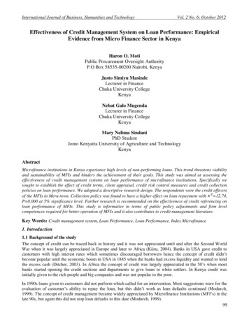
PART AORTHOGRAPHIC PROJECTIONSPictorial View :ORTHOGRAPHIC PROJECTIONS: WITHOUT SECTIONINGDepartment of Mechanical Engineering, BIET., Davanagere 57004.
COMPUTER AIDED MACHINE DRAWING (18ME36)
COMPUTER AIDED MACHINE DRAWING (18ME36)ORTHOGRAPHIC PROJECTIONS: WITH SECTIONINGDepartment of Mechanical Engineering, BIET., Davanagere 57004.3
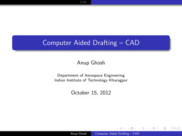
COMPUTER AIDED MACHINE DRAWING (18ME36)PART A THREADFORMSSCREW THREAD TERMINOLOGY:ISO Thread (Indian Standard) - Internal and externalDraw the ISO thread ( Both internal and External) taking pitch, P 50mm. Show at leastthree threads.Department of Mechanical Engineering, BIET., Davanagere 57004.4
COMPUTER AIDED MACHINE DRAWING (18ME36)Whitworth Thread (British Standard) BSW ThreadsDraw Whitworth Thread (British Standard) taking pitch, P 50mm. Show at least threethreads.Sellers Thread (American Standard)Draw Sellers Thread (American Standard)taking pitch, P 30mm. Show at least three threads.Basic Form of Square ThreadDraw Square Thread taking pitch, P 50mm. Show at least three threads.Department of Mechanical Engineering, BIET., Davanagere 57004.5
COMPUTER AIDED MACHINE DRAWING (18ME36)Acme Thread:Draw Acme Thread taking pitch, P 50mm. Show at least threethreads.FASTENERSDepartment of Mechanical Engineering, BIET., Davanagere 57004.6
COMPUTER AIDED MACHINE DRAWING (18ME36)Exercise.1Draw the three views of ISO threaded hexagonal bolt 100mm long, 20mm diameter and a thread lengthof50mm and hexagonal nut assembly in the axis horizontal position .Indicate all the proportions and theactual dimensions.Department of Mechanical Engineering, BIET., Davanagere 57004.7
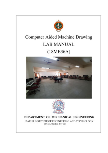
COMPUTER AIDED MACHINE DRAWING (18ME36)Resting on its corner320401181650100Resting on its Face2034,643401850100Department of Mechanical Engineering, BIET., Davanagere 57004.8
COMPUTER AIDED MACHINE DRAWING (18ME36)SQUARE HEADED BOLT, WASHER AND NUT ASSEMBLY:Exercise.2Draw the three views of ISO threaded square bolt 100 mm long, 20 mm diameter and a thread length of50mm and square nut assembly in the axis horizontal position. Show the assembly of bolt and nut in theview across corners across corners and across flats. Indicate all the proportions and the actual dimensions.CORNER PLACED:Across Flats:Department of Mechanical Engineering, BIET., Davanagere 57004.9
COMPUTER AIDED MACHINE DRAWING (18ME36)WASHER :2d 1.5mmd 1mm0.15xdSTUD BOLT AND LOCK NUT ASSEMBLY:d0.6dstudlock nutload nut2d0.9dd1.8d1.5d1.7dNUTS AND BOLTS:Flanged nutDepartment of Mechanical Engineering, BIET., Davanagere 57004.slotted nut10
COMPUTER AIDED MACHINE DRAWING (18ME36)Split pin lock nut assemblyWing nutSlotted nut assemblyGrub screwCounter sung head screwDepartment of Mechanical Engineering, BIET., Davanagere 57004.Allen screw11
COMPUTER AIDED MACHINE DRAWING (18ME36)PART BJOINTSSOCKET AND SPIGOT COTTER JOINTSDraw the following views of an assembled Socket and Spigot Cotter Joint to 1:1 scaleassuming the diameter of the rods d 20mm.1. Front view in half section,2. Top view,3. A view looking from socket end.Department of Mechanical Engineering, BIET., Davanagere 57004.12
COMPUTER AIDED MACHINE DRAWING (18ME36)KNUCKLE JOINTDraw the following views an assembled knuckle joint to 1:1 scale assuming the diameter ofthe rods d 20mm.1. Front view with top half in section,2. Top view,3. A view from the eye end of the rod.Indicate the important assembly dimensions and write the item list.Department of Mechanical Engineering, BIET., Davanagere 57004.13
COMPUTER AIDED MACHINE DRAWING (18ME36)KEYSDepartment of Mechanical Engineering, BIET., Davanagere 57004.14
COMPUTER AIDED MACHINE DRAWING (18ME36)Department of Mechanical Engineering, BIET., Davanagere 57004.15
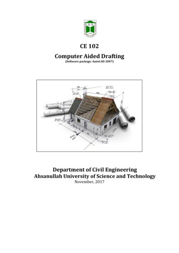
COMPUTER AIDED MACHINE DRAWING (18ME36)COUPLINGS1. Protected type flanged coupling:Following drawing shows the Protected type flanged coupling with proportions expressed in terms ofshaft diameter ‘d 25mm’. Draw the sectional front view and sectional profile view with 1:1 scale.Department of Mechanical Engineering, BIET., Davanagere 57004.16
COMPUTER AIDED MACHINE DRAWING (18ME36)2. Pin (bush) type Flexible coupling:Following drawing shows the Pin (bush) type Flexible coupling with proportions expressed interms of shaft diameter ‘d 25mm’. Draw the sectional front view and sectional profile view with1:1 scale.Department of Mechanical Engineering, BIET., Davanagere 57004.17
COMPUTER AIDED MACHINE DRAWING (18ME36)3. Universal coupling:Following drawing shows the Universal coupling with proportions expressed in terms of shaftdiameter ‘d 25mm’. Draw the sectional front view and sectional profile view with 1:1 scale.Department of Mechanical Engineering, BIET., Davanagere 57004.18
COMPUTER AIDED MACHINE DRAWING (18ME36)4. Split muff coupling:Following drawing shows the split muff coupling with proportions expressed in terms of shaftdiameter ‘d 25mm’. Draw the sectional front view and sectional profile view with 1:1 scale.5. Oldham’scoupling:Following drawing shows the Pin (bush) type Flexible coupling with proportions expressed interms of shaft diameter‘D 25mm’. Draw the sectional front view and sectional profile view with1:1 scale.Department of Mechanical Engineering, BIET., Davanagere 57004.19
COMPUTER AIDED MACHINE DRAWING (18ME36)PART CASSEMBLY DRAWING1. SCREW JACKDepartment of Mechanical Engineering, BIET., Davanagere 57004.20
COMPUTER AIDED MACHINE DRAWING (18ME36).Department of Mechanical Engineering, BIET., Davanagere 57004.21
COMPUTER AIDED MACHINE DRAWING (18ME36)Create the following views in separate sheet along with part list.Sectioned Front view And Top viewDepartment of Mechanical Engineering, BIET., Davanagere 57004.22
COMPUTER AIDED MACHINE DRAWING (18ME36)2.PLUMMERBLOCKDepartment of Mechanical Engineering, BIET., Davanagere 57004.23
COMPUTER AIDED MACHINE DRAWING (18ME36)Department of Mechanical Engineering, BIET., Davanagere 57004.24
COMPUTER AIDED MACHINE DRAWING (18ME36)Create the following views in separate sheet along with part list.HALF SECTIONAL FRONT VIEWLEFT SIDE VIEWTOP VIEWDepartment of Mechanical Engineering, BIET., Davanagere 57004.25
COMPUTER AIDED MACHINE DRAWING (18ME36)3. ASSEMBLY OF MACHICE VICEDepartment of Mechanical Engineering, BIET., Davanagere 57004.26
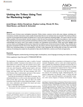
COMPUTER AIDED MACHINE DRAWING (18ME36)Exercise 2:The details of a MACHICE VICE are shown in Fig. Draw the following views of theassembled vice to 1:1 scale with the jaws spread to hold the work-piece of maximum size.1. Half sectional front view showing fixed jaw in section.2. Top view.3. Left view.Department of Mechanical Engineering, BIET., Davanagere 57004.27
COMPUTER AIDED MACHINE DRAWING (18ME36)Create the following views in separate sheet along with part list.SECTIONAL FRONT VIEWLEFT SIDE VIEWMOVEABLE JAW IN SECTIONTOP VIEWDepartment of Mechanical Engineering, BIET., Davanagere 57004.28
COMPUTER AIDED MACHINE DRAWING (18ME36)4. ASSEMBLY OF PETROL ENGINE CONNECTING RODDepartment of Mechanical Engineering, BIET., Davanagere 57004.29
COMPUTER AIDED MACHINE DRAWING (18ME36)Fig. shows the details of a PETROL ENGINE CONNECTING ROD. Draw the following assembledviews of the connecting rod with its axis horizontal to 2:1 scale.1. Front view with top half in section.2. Top view with front half in section.3. Side view with bottom half in section looking from the big end.Department of Mechanical Engineering, BIET., Davanagere 57004.30
COMPUTER AIDED MACHINE DRAWING (18ME36)Create the following views in separate sheet along with part list.ISOMETRIC VIEWHalf sectioned front and top viewDepartment of Mechanical Engineering, BIET., Davanagere 57004.31
COMPUTER AIDED MACHINE DRAWING (18ME36)5. ASSEMBLY OF TAIL STOCK OF A LATHEDepartment of Mechanical Engineering, BIET., Davanagere 57004.32
COMPUTER AIDED MACHINE DRAWING (18ME36)Figure shows the details of a tail stock of a lathe. Assemble the parts and drawi) Front viewii) Top viewiii) Side view looking from hand wheel.Department of Mechanical Engineering, BIET., Davanagere 57004.33
COMPUTER AIDED MACHINE DRAWING (18ME36)Create the following views in separate sheet along with part list.Top , Front and Side viewsIsometric viewDepartment of Mechanical Engineering, BIET., Davanagere 57004.34
INSTRUCTION FOR COMPUTER AIDED MACHINE DRAWING (15ME36A/46A) EXAMINATION 1. No restriction of timing for sketching/ computerization of solutions. The total duration is 3 hours. 2. It is desirable to do sketching of all the solutions before computerizat