Transcription
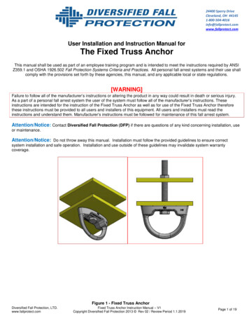
24400 Sperry DriveCleveland, OH tect.comUser Installation and Instruction Manual forThe Portable Truss AnchorThis manual shall be used as part of an employee training program and is intended to meet the Instructions required by ANSIZ359.1 and OSHA 1926.502 Fall Protection Systems Criteria and Practices. All personal fall arrest systems and their use shallcomply with the provisions set forth by these agencies, this manual, and any applicable local or state regulations.[WARNING]Failure to follow all of the manufacturer’s instructions or altering the product in any way could result in death or serious injury. As apart of a personal fall arrest system the user of the system must follow all of the manufacturer’s instructions. These instructionsare intended for the instruction of the Portable Truss Anchor as well as for use of the Portable Truss Anchor therefore theseinstructions must be provided to all users and installers of this equipment. All users and installers must read the instructions andunderstand them. Manufacturer’s instructions must be followed for maintenance of this fall arrest system.Attention/Notice: Contact Diversified Fall Protection (DFP) if there are questions of any kind concerning installation, use ormaintenance.Figure 1 – Portable Truss AnchorAttention/Notice: Do not throw away this manual. Installation must follow the provided guidelines to ensure correct systeminstallation and safe operation. Installation and use outside of these guidelines may invalidate system warranty and insurancecoverage.Diversified Fall Protection, LLC.www.fallprotect.comPortable Truss Anchor Instruction Manual – V 1Copyright Diversified Fall Protection 2013 Page 1 of 16
I. Applications:A.Purpose:The purpose of the portable truss anchor is to be used as an anchor point of a personal fall arrest system. It isdesigned to be used with a full body harness with back D-Ring, a carabiner, and a connecting subsystem consisting ofa self-retracting lifeline (SRL).B.Limitations: Capacity – The portable truss anchor is not to be used by persons with a total weight over 420 pounds. Thistotal weight includes body weight, and the weight of any clothing, tools, and equipment. Fall Clearance – In general industry, when working on a surface 4 feet or higher from ground level, perOSHA, fall protection is required. This system is designed to prevent serious injury or death in the event of afall. There must be sufficient clearance below the user to arrest a fall before the user strikes the ground orother obstruction. Clearance required may increase depending on but notlimited to some of the following factors: worker height, worker weight,movement of attachment element, elevation of anchorage connector, SRLlength, other obstructions, deceleration distance and free fall distance.Figure 2 - Fall Clearances WARNING: Working surface must be atleast 6’6” from the ground surface when user is in upright standingposition to prevent serious injury and/or death.C. Swing Falls – A swing fall occurs when the anchor point is not directly aboveFigure 3 - Safe Work Areawhere a fall occurs. Minimize this hazard by working with the anchor overheadas much as possible. The suggested safe work area is within a 30º downward facing cone from an overheadanchor point to harness D-Ring (See Figure 3). The extra force of striking an object in a swing fall may causeserious injury or death and should therefore be avoided whenever possible. The required clearancesignificantly increases when a variable length subsystem such as a web lanyard is used. Environmental Hazards – Extra precautions may be required to safely use this system if other hazards in thesurrounding environment exist. Such hazards include, but are not limited to: extreme temperatures, powerlines, moving machinery, sharp edges, corrosion, and toxic fumes. Please contact DFP if you have concernof any such conditions existing where this equipment is being used. Training – This equipment is only permitted to be installed and used by competent persons that have beentrained in the correct use and application of the portable truss anchor.Standards: Please refer to all families of standards regarding occupational safety for more information on work positioningsystems and fall protection. These include ANSI, OSHA, and any applicable local or state requirements.II. System Requirements:A.Compatibility: Compatibility shall follow all requirements of OSHA 1926.502 (d) as well as these instructions and those of theSRL, harness, and other components. The design of the portable truss anchor is made for use only with approved components and subsystems.Non-approved components and subsystems may jeopardize the compatibility of equipment and affect thesafety and reliability of the complete system.Diversified Fall Protection, LLC.www.fallprotect.comPortable Truss Anchor Instruction Manual – V 1Copyright Diversified Fall Protection 2013 Page 2 of 16
B. A connector is considered compatible with the portable truss anchor when they have been designed to worktogether in a manner that the gate mechanism cannot accidentally be opened no matter how they becomeoriented. Connectors must be compatible with the attachment point and must be capable of supporting a minimum of5000 pounds. Do not use a non-compatible connector as it may unintentionally disengage. Connectors mustbe compatible in strength, size, and shape. Self-locking snap hooks and carabiners are required by ANSI andOSHA.Connections: Only use of snaphooks and carabiners meeting ANSI Z359.1-2007 3.2.1.4 are permitted for use with thisequipment. This requires that “snaphooks and carabiners shall be self-closing and self-locking and shall becapable of being opened only by at least two consecutive deliberate actions”. Furthermore, “the gate of asnaphook or carabiner shall be capable of withstanding a minimum load of 3,600 pounds without the gateseparating from the nose of the snaphook or carabiner body by more than .125 inches”. All connectors mustbe compatible in size, strength, and shape. Ensure all connectors are fully closed and locked. Snap hooks and carabiners shall never be connected:ooooooC.D.Personal Fall Arrest System: A full body harness must be worn when this equipment is used as a component of the fall arrest system. OSHA requires that a fall arrest system must be capable of arresting the user’s fall with a max arresting force(MAF) of 1800 pounds. DFP designed this system with a max limit of 900 pounds. OSHA requires that the free fall limit is 6 feet or less. This system has been designed for use with a web or cable style self-retracting lifeline. Lanyards are notpermitted to be used with this system.Anchorage Strength: The required strength is dependent on the type of application that is being used. ANSI Z359.1 requiressystems to have a strength capable of sustaining static loads as follows:ooIII.To an attachment point where another connecter is already attached.In a way that would result in a load on a gate.In false engagement where features that protrude from the connector catch on the anchor and seemsto be fully engaged without visual confirmation.To each other.Directly to webbing, rope lanyard, or tie-back.To any object which will not allow the connector to close and lock or which a roll-out could occur.Fall Arrest:(a) 5000 pounds for non-certified anchorages(b) Two times the MAF for certified anchorages.Rescue:(a) 3000 pounds for non-certified anchorages(b) Five times the foreseeable force for certified anchorages If multiple systems are being attached to the same anchorage point in any of the prior applications, thestrengths defined shall be multiplied by the number of systems attached to the anchorage. WARNING: The anchorage connector shall be marked or labeled with its intended application. Use ofequipment for an application that does not meet the strength requirements can result in serious injuryor death.Installation and Use:Diversified Fall Protection, LLC.www.fallprotect.comPortable Truss Anchor Instruction Manual – V 1Copyright Diversified Fall Protection 2013 Page 3 of 16
WARNING: Prior to install, all instructions must be read and understood for each component of thispersonal fall arrest system. WARNING: Do not alter or misuse this equipment. Consult DFP before using the portable trussanchor with any other component or subsystem than designed for. Other components may interferewith the proper operation of this equipment. Use extra caution around electricity, moving machinery,chemical hazards, and sharp edges. WARNING: Pregnant women and minors must not use the portable truss anchor system. Age andfitness also affect the ability to withstand falls. Consult your doctor if you have any doubts regardingyour ability to safely absorb a shock from a fall arrest. WARNING: Proper Personal Protective Equipment must be worn throughout the entire installationprocess. OSHA 1910.135(a)(1) states “each affected employee wears a protective helmet whenworking in areas where there is a potential for injury to the head from falling objects.” Protectiveeyewear is also required as part of this system. WARNING: Avoid power lines and any other potential overhead hazards when extending and raisingthe extension pole. Maintain a minimum 10 foot distance from any electrical hazard.A.Plan your system prior to installation. Consider any factor that may affect a user’s safety. Key points to consider are:anchorage, sharp edges, post-fall lock out, and rescue.B.Installation Requirements: Anchor Locations - Truss anchorage locations must be approved by a safety engineer or a qualified person andmust meet all of the requirements of these instructions.1.2.3.4.May not be at the end of a truss.May not be between the first and second panel point.Must be located between two panel points.Should be as close to a panel point as possible.Figure 4 – Anchor LocationsDiversified Fall Protection, LLC.www.fallprotect.comPortable Truss Anchor Instruction Manual – V 1Copyright Diversified Fall Protection 2013 Page 4 of 16
Truss Requirements1. Bottom Chord (See Figure 5):oooooDepth, D, of bottom chord vertical leg of angles must be between 1 1/4 inch and 3 inch.The thickness, Y, of the bottom chord must be a minimum of 1/4 inch.The gap, S, must be a minimum of 3/4 inch.The width of the space and legs, X, must be a maximum of 2”.Must be hot rolled steel with minimum tensile yield strength of 36 ksi.Figure 5 – Bottom Chord Detail2. Truss SpanooooooBracing shall be straight, undamaged, and meet the original design intent.The span and loading of the truss affects the allowable concentrated load that may be applied to thetruss. It must be capable of withstanding a concentrated load of 900 pounds with a safety factor of two(2) for certified anchorages and 5000 pounds for non-certified anchorages.No more than one user is permitted at a time per truss.Do not attach to a truss that is smaller than 18” in height (See figure 4).An acceptable truss must be designed according to the Steel Joist Institute (SJI) and be a K, KCS, LH, orDLH series truss.The truss must be inspected by an engineer or qualified person for structural integrity whichincludes but is not limited to corrosion, end connections, size, load capacity, welds, existingloading, bracing, span, or any other unsafe conditions.Diversified Fall Protection, LLC.www.fallprotect.comPortable Truss Anchor Instruction Manual – V 1Copyright Diversified Fall Protection 2013 Page 5 of 16
C.Installation1. Attach anchor to pole by rotating anchor clockwise. Ensure that anchor is attached securely. See Figure 6.Figure 6 - Attach Anchor to Pole2. Connect SRL to anchor using the caribineer provided. Also refer to SRL manufacturer instructions. See Figure7.Figure 7 - SRL Attached to Anchor via Carabiner3. Visually inspect connection to make sure the anchor is secured to the pole.4. Test attachment by pulling SRL away from anchor to ensure they are connected.5. Pull out SRL snap hook and attach to eye bolt at the bottom of pole. See Figure 8.Figure 8 - Snap Hook Attached to Eye BoltDiversified Fall Protection, LLC.www.fallprotect.comPortable Truss Anchor Instruction Manual – V 1Copyright Diversified Fall Protection 2013 Page 6 of 16
6. Adjust pole to the proper length and lock in place.7. Use Included Base Plate to stand pole straight up.8. With the pole, raise the anchor above you. Keep the pole as vertical as possible. See Figure 9.Figure 9 - Raise AnchorDiversified Fall Protection, LLC.www.fallprotect.comPortable Truss Anchor Instruction Manual – V 1Copyright Diversified Fall Protection 2013 Page 7 of 16
9. Insert anchor between the bottom chord angles. See Figure 10.Figure 10 - Insert Anchor10. Raise anchor, rotate 90º clockwise. See Figure 11.Figure 11 – Rotate 90 DegreesDiversified Fall Protection, LLC.www.fallprotect.comPortable Truss Anchor Instruction Manual – V 1Copyright Diversified Fall Protection 2013 Page 8 of 16
11. Lower anchor so bearing points sit squarely on vertical legs of the bottom chord of building truss (See figure 12).Figure 12 – Lower Anchor on Truss12. Check visually to make sure anchor is properly sitting on the truss. PROPER ANCHOR PLACEMENT (Figure 13)YES!!Figure 13 INPROPER ANCHOR PLACEMENT (Figures 14 – 17)NO!!Figure 14 - Anchor bearingpoints do not rest on truss legsDiversified Fall Protection, LLC.www.fallprotect.comPortable Truss Anchor Instruction Manual – V 1Copyright Diversified Fall Protection 2013 Figure 15 - Anchor is tooclose to end of trussPage 9 of 16
NO!!Figure 16 - Anchor is notproperly rotatedFigure 17 - Obstructionpreventing anchor from sittingon truss13. Check connection physically by pulling downwards on the pole.14. Disconnect snap hook from eye bolt. See Figure 18.Figure 18 - Disconnect Snap Hook15. While standing on the ground, connect to back D-Ring of full body harness following the manufacturer’sinstructions. See Figure 19.Figure 19 - Connect Snaphook to HarnessAnchor Rated for 420 Pound CapacityEntire System Rated for 310 Pound CapacityDiversified Fall Protection, LLC.www.fallprotect.comPortable Truss Anchor Instruction Manual – V 1Copyright Diversified Fall Protection 2013 Page 10 of 16
16. It is now safe to ascend up ladder, steps, or stairs.17. To disconnect, descend to ground level. Then repeat steps 1 - 16 in reverse.D.Thoroughly inspect equipment for damage before each use.E.The anchor must be above the user’s head. Keeping the anchor directly above the user will help prevent swing falls.This will minimize injury and prevent death in the event of a fall.IV.Training:A.It is the responsibility of the end user to be familiar with these instructions regarding use of the portable truss anchorsystem. The end user is also responsible for the correct care, use, characteristics, limitations, and consequences ofmisuse of this equipment.B.Training is to be conducted prior to initial installation of the system. It should also be repeated on a regular basis.Training must be performed without the user being exposed to an actual fall hazard. The end user is to keep trainingdocumentation on file.V.Inspection:A.The portable truss anchor is to be inspected for damage (bends, cracks, excessive wear, signs of permanentdeformation) before each use.B.A formal inspection of the entire system shall be conducted at least annually. This inspection shall be performed by acompetent or qualified person that is not the end user. The results are to be recorded in the inspection andmaintenance log.C.D.VI.Inspection Procedure: Inspect portable truss anchor for any damage or corrosion. Pay close attention for any signs of permanentdeformation such as cracks or wear that could jeopardize the integrity of the strength of the system. Inspect the truss attachment points. The anchor must be securely positioned on the truss. Inspect all system components. Make copies of the inspection log included at the end of this manual. Use it to record inspection results of allcomponents used with the anchor.If inspection reveals any damage or unsafe conditions, immediately remove anchor from service and contactDiversified Fall Protection for further instructions.Maintenance Clean the portable truss anchor with a mild solution of soap and water. This will prevent excessive build-up ofdirt and other debris that could prevent proper operation. Store equipment in a secured clean, dry, and non-corrosive environment. Keep equipment records which contain data pertaining to any maintenance or incidents.Diversified Fall Protection, LLC.www.fallprotect.comPortable Truss Anchor Instruction Manual – V 1Copyright Diversified Fall Protection 2013 Page 11 of 16
VII.Specifications and PartsA. System as an assembly is rated for a 310 pound user. Contact DFP if 420 pound capacity is requiredB. Portable Truss Anchor (See Figure 20)Main Body Material : ½” Thick A36 Steel Finish: Powder Coat Safety YellowThreaded Attachment Material: Plain Steel – Rockwell Hardness B75 Right hand thread ¾” Diameter Finish: Powder Coat Safety YellowWeld Weld by AWS D1.1 Certified welder in conjunction with the requirements of OSHA Electrode has a minimum tensile strength of 70 ksiFigure 20 - AnchorDimensionsMaximum Allowable loading One (1) 420 Pound Usero When used independently of this system Mass Arresting Force of 900 LbsC. Extension Pole (See Figure 21)Main Body Material: smooth 1-¼”round fiberglass handle Color: Yellow Reach: 6’-18’ (1.8m-5.4m) 3-section extension poleTelescoping Slider Tubes Size: 1” (2.5 cm) and 7/8”(2.2 cm) diameter round Material: aluminum Finish: Clear anodizedThreaded End Material: Cast AluminumExternal Locking Device x2 (See Figure 22) Material: Plastic Mechanism: Compression lock with course threads Color: Outer sleeve is blackInternal sleeve is redFigure 22 ExternalLockingDevice on PoleHandle Grip Black rubber gripClamp and Eyebolt Body: Zinc plated steelFigure 21 Liner: UV-resistant EPDM Rubber , ASTM E-84Extension Pole Meets Buy America Act Eyebolt: 3/8”-16 Steel Zinc Plated 144 pound work load Limit Screw Protector: Black pliable vinyl with a durometer of 75ADiversified Fall Protection, LLC.www.fallprotect.comPortable Truss Anchor Instruction Manual – V 1Copyright Diversified Fall Protection 2013 Page 12 of 16
D. Self-Retracting Lifeline (Figure 23) 20ft Rebel Part Number 3100431 with AJ520A hook on lifeline, AJ514Acarabineer on housing (See Figure 18) Webbing: 20 feet of 1” wide polyester webbing (shock absorber is nylon) Housing: Anodized aluminum Stainless Steel: Drum spring, pawls, pawl springs and external fasteners Alloy Steel/Plated: Shaft, ratchet plate, and end plates Snap Hook: AJ520A, zinc plated alloy steel 5000 lb. min. tensile strength. Capacity: 310 pounds when used independently of the system. Weight: 5.1 lbs. with AJ520A hook & Carabineer Size: 5.5” diameter x 2” thick Max. Arresting Force: 900 lbs.D. Full Body Harness (See Figures 24 & 25)Repel Technology Webbing: Material Polyester Width 1.75 in (4.45cm) T. Strength Stan 6,000lbs (2,722 kg) Belt 11,000lbs (4,990 kg) T&B 8,800lbs (3,992 kg) Treatment: NanosphereComfort Padding Hip padding Materials (where applicable) Nylon & Polyester Dri-Lex Aerospace Mesh EVA Foam 420D PVC fabricFigure 23 - Rebel SRLFigure 24 -DeltaHarness, Front ViewTech Lite Quick Connect Buckle (See Figure 27) Materials 7075 & 6061 Aluminum Alloy Stainless Steel per ASTM A240 Alloy Steel SAE AMS 6350 (zinc plated finish) T. Strength 4,000lbs (1,815kg)Revolver Vertical Torso Adjustor (See Figure 26) Materials Alloy Steel AISI 4140 (zinc plated finish) Stainless Steel Nylon 6-6 T. Strength 4,000lbs (1,815kg)Figure 25 - DeltaHarness, Back ViewFigure 26 Quick ConnectBuckleFigure 27 - TorsoAdjusterD-rings (See Figure 28) Material Heat treated Alloy Steel with zinc plate finish T-Strength 5,000 lbs (2,268 kg)No-Tangle D-ring Pad (See Figure 28) Material UrethaneLabels Material VinylThread Material High Strength PolyesterFigure 28 - D-Ring &No-Tangle PadRated for 420 Pound Capacity when used independently of the system.Diversified Fall Protection, LLC.www.fallprotect.comPortable Truss Anchor Instruction Manual – V 1Copyright Diversified Fall Protection 2013 Page 13 of 16
VIII.LabelingThe following label must be present and fully legible:Figure 32 – Required Tags WARNING: If label is missing from anchor, remove from service and contact DFP immediately.Diversified Fall Protection, LLC.www.fallprotect.comPortable Truss Anchor Instruction Manual – V 1Copyright Diversified Fall Protection 2013 Page 14 of 16
IX.Inspection and Maintenance LogInspection DateInspection Items NotedCorrective ActionMaintenance PerformedApproved by:Approved by:Approved by:Approved by:Approved by:Approved by:Approved by:Approved by:Approved by:Approved by:Approved by:Approved by:Approved by:Approved by:Approved by:Approved by:Approved by:Approved by:Approved by:Approved by:Approved by:Diversified Fall Protection, LLC.www.fallprotect.comPortable Truss Anchor Instruction Manual – V 1Copyright Diversified Fall Protection 2013 Page 15 of 16
Diversified Fall Protection, LLC.www.fallprotect.comPortable Truss Anchor Instruction Manual – V 1Copyright Diversified Fall Protection 2013 Page 16 of 16
User Installation and Instruction Manual for The Portable Truss Anchor Thisanual shall be used as part of an employee training program and is intended to meet the m Instructions required by ANSI Z359.1 and OSHA 1926.502 Fall Protection Systems Criteria and Practices. All personal