Transcription
Energy Absorbing LanyardUser Instruction ManualThis manual is intended to meet the Manufacturer’s Instructions as required by the Canadian Standards Association(CSA) Z259 and should be used as part of an employee training program.CMSAL01 Rev AFallTech 1306 S. Alameda Street Compton, CA 90221, USA Tel: 800-719-4619 Fax: 323-752-5613060419
Table of Contents1.0Warnings and Important Information .32.0Description .43.0Application .44.0System Requirements .55.0Installation and Use .66.0Maintenance, Service and Storage .97.0Inspection .98.0Labels . 11Appendix A .12For purposes of this manual, the FallTech Energy Absorbing Lanyards in all iterations may be referred to collectively as the FallTech EAL ,the Energy Absorbing Lanyard, the EAL, the equipment, the device, the product, or the unit.CMSAL01 Rev A0604192
1.0Warnings and Important InformationWARNING Avoid moving machinery, thermal, electrical and/or chemical hazards as contact may cause serious injury or death.Avoid swing falls.Follow the weight restrictions and recommendations in this manual.Remove from service any equipment subjected to fall arrest forces.Remove from service any equipment that fails inspection.Do not alter or intentionally misuse this equipment.Consult FallTech when using this equipment in combination with components or subsystems other than those described in this manual.Do not connect rebar hooks, large carabiners, or large snap hooks to the FBH dorsal D-rings as this may cause a roll-out condition and/orunintentional disengagement.Avoid sharp and/or abrasive surfaces and edges.Use caution when performing arc welding. Arc flash from arc welding operations, including accidental arcs from electrical equipment, candamage equipment and are potentially fatal.Examine the work area. Be aware of the surroundings and workplace hazards that may impact safety, security, and the functioning of fall arrestsystems and components.Hazards may include but not be limited to cable or debris tripping hazards, equipment failures, personnel mistakes, moving equipment such ascarts, barrows, fork lifts, cranes, or dollies. Do not allow materials, tools or equipment in transit to contact any part of the fall arrest system.Do not work under suspended loads.IMPORTANTThis product is part of a personal fall arrest, restraint, work positioning, suspension, or rescue system. A Personal Fall Arrest System (PFAS) istypically composed of an anchorage and a Full Body Harness (FBH), with a connecting device, i.e., an Energy Absorbing Lanyard (EAL), or aSelf-Retracting Device (SRD), attached to the dorsal D-ring of the FBH.These instructions must be provided to the worker using this equipment. The worker must read and understand the manufacturer’s instructions foreach component or part of the complete system. Manufacturer’s instructions must be followed for proper use, care, and maintenance of thisproduct. These instructions must be retained and be kept available for the worker’s reference at all times. Alterations or misuse of this product, orfailure to follow instructions, may result in serious injury or death.A Fall Protection Plan must be on file and available for review by all workers. It is the responsibility of the worker and the purchaser of thisequipment to assure that users of this equipment are properly trained in its use, maintenance, and storage. Training must be repeated at regularintervals. Training must not subject the trainee to fall hazards.Consult a doctor if there is reason to doubt your fitness to safely absorb the shock of a fall event. Age and fitness seriously affect a worker’s abilityto withstand falls. Pregnant women or minors must not use this equipment.Heavy users experience more risk of serious injury or death due to falls because of increased fall arrest forces placed on the user’s body. In addition,the onset of suspension trauma after a fall even may be accelerated for heavy users.The user of the equipment discussed in this manual must read and understand the entire manual before beginning work.NOTE: For more information consult the CSA Z259 body of standards.CMSAL01 Rev A0604193
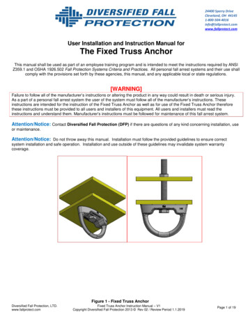
2.0DescriptionThe FallTech Energy Absorbing Lanyard (EAL) constitutes both the connection and energy absorption components of your Personal FallArrest System (PFAS). When properly employed, a FallTech EAL will allow the user to work safely and comfortably. An EAL is part of aPFAS requiring a compatible and properly rated anchor and/or anchorage connector and dorsal connection point on a Full BodyHarness (FBH).FallTech EALs are available in a wide variety of configurations to address the specific needs in most workplaces. The suitability of anEnergy Absorbing Lanyard for a specific application is determined primarily by the type and location of the anchorages or anchorageconnectors. See Figure 1 for a Single-Leg and Y-Leg lanyard configuration.Figure 1 - About FallTech Energy Absorbing Lanyards112321Anchorage Connector2Energy Absorber3Harness Attachment Connector3WARNINGAlways read and follow the manufacturer’s instructions, labels, and warnings before use.Failure to do so can result in serious injury or death.3.0Application3.1 Purpose: The FallTech EAL is designed for use as a component in a PFAS, to provide a combination of worker mobility and fallprotection as required for inspection work, general construction, maintenance work, oil production, confined space work or anyapplication where fall protection and worker mobility is required.3.2 Personal Fall Arrest System: A PFAS is typically composed of an anchorage and a FBH, with an energy absorbing connecting device,i.e., a EAL, an SRD, or a Fall Arrester Connecting Subsystem (FACSS), attached to the dorsal D‐ring of properly fitted and adjusted FBH. Alluses and applications of a FBH with this equipment requires the FBH to be properly fitted and adjusted to the user. Failure to properlyfit the FBH to the user could result in serious injury or death.3.3 Application Limits: The FallTech EALs are a dynamic anchorage subsystem that varies in its performance depending upon the lengthof the system, and the type of PFAS system used. Care should be taken to understand the capacity of the system, anchorage strengthrequirements, total allowable free fall; the Energy Absorbing Lanyard used, and the requirements how the user’s PFAS deploys during afall event. The longer the freefall, the greater the energy in the system the further the EAL stretches during a fall event and result in moresignificant clearance requirements and impact forces on the body.3.4 Approved Applications: Below are applications for which all FallTech Energy Absorbing Lanyards are specifically suited. This list is notall-inclusive, but is intended to anticipate the most common applications in which this product may be used.3.4.1 Direct Overhead Applications: All FallTech EALs are suitable for use in any application where the properly ratedanchorage is directly above the walking/working surface, and allows for a maximum Free-Fall Distance of 1.8 m (6 ft) unless it isa specialty application, see Section 3.5.3.4.2 Horizontal Lifelines: All FallTech EALs are suitable for use in any application where a horizontal lifeline has been installedunder the guidance of a qualified person, and where the Free-Fall Distance does not exceed 1.8 m (6 ft).3.4.3 Arc Flash: Arc Flash lanyards are suitable where electric arc and arc-blast exposures are present.CMSAL01 Rev A0604194
3.5 Specialty Applications:3.5.1 100% Tie-Off: EALs made for 100% Tie-Off are generally referred to as “Y”-lanyards or dual-leg lanyards. These productshave two legs joined to a single connector on the attachment-end (the end that attaches to your full body harness) with a singleconnector on the opposite end of each leg for tying off to the anchorage connector(s). The second leg gives you the abilityto safely transition from one anchor point to another without having to disconnect from the structure entirely during thetransition process.3.5.2 Welding/Power Transmission: For welding applications and for use in environments where high heat may pose a hazard.Intended to be used in Power Transmission or in applications where the user may be exposed to an electrical arc hazard.4.0System Requirements4.1 Capacity: See Chart 1 in Section 5.3.1 for additional information.4.2 Compatibility of Connectors: Connectors are considered to be compatible with connecting elements when they have been designedto work together in such a way that their sizes and shapes do not cause their gate mechanisms to open inadvertently regardless of howthey become oriented. Contact FallTech if you have any questions about compatibility. Connectors must be compatible with theanchorage or other system components. Do not use equipment that is not compatible. Non-compatible connectors may unintentionallydisengage. Connectors must be compatible in size, shape, and strength. Self-closing, self-locking connectors are required by CSA.4.3 Making Connections: Only use self-locking connectors with this equipment. Only use connectors that are suitable to each application.Ensure all connections are compatible in size, shape, and strength. Do not use equipment that is not compatible. Visually ensure allconnectors are fully closed and locked. Connectors (snap hooks, rebar hooks, and carabiners) are designed for use only as specified in thismanual.Figure 2 - Non-Compatible ConnectionsANever connect two active components (snap hooks or carabiners)to each other.BNever connect two active components (snap hooks or carabiners)to a single D-ring at the same time.CNever connect in a way that would produce a condition of loadingon the gate.DNever attach to a object in a manner whereby the gate (of thesnap hook or carabiner) would beprevented from fully closing and locking. Always guard againstfalse connections by visually inspecting for closure and lock.ENever attach explicitly to a constituent subcomponent (webbing,cable or rope) unless specifically provided for by the manufacturer’s instructions for both subcomponents (snap hook or carabinerand webbing, cable or rope).FNever attach in a manner where an element of the connector(gate or release lever) may become caught on the anchor therebyproducing additional risk of false engagement.GNever attach a spreader snap hook to two side/positioningD-rings in a manner whereby the D-rings will engage the gates;the gates on a spreader must always be facing away from theD-rings during work positioning.4.5 Personal Fall Arrest System: A PFAS is an assembly of components and subsystems used to arrest a person during a fall event. A PFASis typically composed of an anchorage and a FBH, with an energy absorbing connecting device, i.e., an EAL, an SRD, or a Fall ArresterConnecting Subsystem (FACSS), connected to the dorsal D-ring of the FBH. PFAS components used in conjunction with this SRD shouldcomply with CSA Z259 requirements.4.6 Personal Fall Arrest System Anchorage Strength: An anchorage selected for PFAS application must have the strength to sustain a staticload applied in the direction permitted by the PFAS of at least two times the maximum arrest force permitted when certification exists, or22.2 kN (5,000 lbs) in the absence of certification.Select an anchorage location carefully. Consider structural strength, obstructions in the fall path, and swing fall hazards. In certainsituations, the qualified person can determine that a given structure is able to withstand the applied MAF of the PFAS with a safety factorof at least two.CMSAL01 Rev A0604195
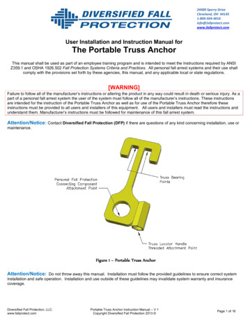
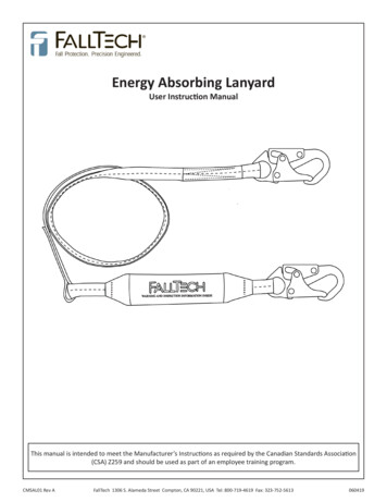
5.0Installation and UseWARNINGDo not alter or intentionally misuse this equipment. Consult FallTech when using this equipment in combination with components orsubsystems other than those described in this manual. All components or subsystems used with the EAL discussed in this manual must be incompliance with CSA Z259.Do not use rebar hooks, large carabiners, or large snap hooks to connect to the FBH dorsal D-rings or to any small diameter non-compatibleanchor point as this may cause a roll-out condition and/or unintentional disengagement.Use caution. Take action to avoid sharp and/or abrasive surfaces and edges when possible.5.1. Plan the Personal Fall Arrest System (PFAS): Examine the work area and take action to address hazards. Falls are a serious hazardwhen working at height. Training and equipment are the tools of fall hazard management. There are several closely related facets of fallhazard management with a PFAS: AnchorageMinimum Required Fall Clearance (MRFC)Swing Fall and Expanded Work ZoneOverhead (above the FBH D‐ring) AnchorageNon‐overhead (below the FBH D‐ring) AnchorageRescue Plan5.2 Anchorage: Select a suitable anchor point. See Section 4.6. Determine the anchor point location relative to the height of the user’sFBH D‐ring. Also, consider how many feet of lateral travel the work will require. To avoid an unintended disengagement of connectors,use only compatible connectors when connecting to the anchorage. Ensure all connectors close and lock securely.5.3 Minimum Required Fall Clearance: The MRFC is the minimum distance a user needs between himself and the nearest obstruction (orground) below the walking/working surface to avoid serious injury or death in case of a fall event. The user of this equipment mustdetermine the MRFC for units discussed in this manual to ensure adequate clearance exists in the fall path, see Figure 3.5.3.1 Calculating MFRC in Overhead Configuration: Use Chart 1 to calculate the elongation/deployment distance based on theworker weight including tool and equipment and free fall distance.Figure 3 - Minimum Required Fall Clearance - Overhead1AABC2BDDEE3CMSAL01 Rev AFCFLength of Shock Absorbing LanyardOriginal working length before a fall event occurs/beforeactivation of energy absorberElongation/Deceleration Distance*1.4 m (4 1/2 ft) Maximum allowable among of elongation that may payoutfrom the energy absorber upon activation during a fall eventHarness Stretch and Dorsal D-Ring Shift0.5 m (1 1/2 ft) Combined amount of harness webbing elongation and dorsalback D-Ring up-shift during entire fall event1.8 m (6 ft)Height of Dorsal D-RingTypical average height of the dorsal D-Ring on a user’s fullbody harness, measured from the walking/working surface upSafety Factor0.5 m (1 1/2 ft) Added length for other factors such as an improperly adjustedharness, actual worker height or worker weight5.5 m (18 ft) Total Minimum Clear Fall Distance Required* Worse case value, see Chart 1 for actual values based on user weight1. Overhead Anchorage 2. Walking/Working Surface3. Nearest Lower Level or Obstruction1.5 m (5 ft)0604196
Chart 1 - Energy Absorber DeploymentWorker weight is the combined weight of user, tools, clothing, etc.Energy Absorber Deployment (m)If the user is in between the increments listed in the graph, thenext highest weight bracket shall be used.159 kg136 kg113 kg91 kg68 kg54 kgFree Fall Distance (m)5.3.2 Swing Fall: A swing fall occurs when the worker moves laterally out from under the anchor and creates an expanded workzone condition. If a fall event occurs, the worker would swing back toward the anchorage, see Figure 4. The swinging actiongenerates considerable force, and if the worker strikes an obstruction or the lower level, this force could cause severe injury ordeath.Figure 4- Swing Fall HazardCMSAL01 Rev A060419AAnchorageBEnergy Absorbing LanyardCWalking/Working SurfaceDSwing Fall Impact After Fall EventENext Lower Level or Obstruction7
5.4 Pre-Use Inspection: FallTech requires that the following steps be taken during each inspection prior to use of this Energy AbsorbingLanyard:1.Check the webbing/cable and look for cuts, fraying, and signs of damage from excessive wear or abrasion. Also look for excessivedirt, grease, oil, paint, or other surface contamination or discoloring. If any condition exists that compromises the integrity of thewebbing, changes the general properties or feel of the webbing, or limits/restricts the adjustment of the webbing, immediatelyremove the EAL from service.2. Check all stitch locations. Ensure that each stitch box and bar-tack is intact with no loose, frayed, or torn threads. If any of the stitchlocations shows signs of damage or excessive wear, immediately remove the EAL from service.5.5 Lanyard Use Instructions by Type:5.5.1 Single-Leg Lanyards - Overhead1.2.Attach the EAL to the dorsal D-ring of your Full Body Harness at the attachment end. The Attachment-End Connector isalways adjacent to the energy absorber, see Figure 5. Ensure the gate closes and locks and that the D-ring is fully engagedby the snap hook.Connect the leg-end connector to a properly rated fall protection anchorage connector.Figure 5 - Single-Leg Lanyard Overhead134521Overhead Anchorage2Walking/Working Surface3Anchorage End Connector4Attachment End Connector5Energy Absorber5.5.2 Y-Leg Lanyards - Overhead1.2.Attach the EAL to the dorsal D-ring of your Full Body Harness at the attachment end. The Attachment-End Connector is alwaysadjacent to the energy absorber, see Figure 5. Ensure the gate closes and locks and that the D-ring is fully engaged by the snaphook.The Y-Leg lanyard is designed for 100% tie-off as you move from one work location to another. The dual connection is fortransitioning only, see Figure 6. Attach one leg end connector to a suitable anchor. The user may then move to another worklocation and attach the unused leg to the next suitable anchorage and removing the previous leg. Repeat the procedure, untilthe desired work location is reached.Figure 6 - Y-Leg Lanyard Overhead5.5.3 Specialty Applications - WeldTech1.2.CMSAL01 Rev AAttach the EAL to the dorsal D-ring of your Full Body Harness at the attachment end. The Attachment-End Connector is alwaysadjacent to the energy absorber, see Figure 5. Ensure the gate closes and locks and that the D-ring is fully engaged by the snaphook.The WeldTech Lanyards are designed for use in hot-work welding environments and have a high heat and burn resistance.Available in both Single-Leg and Y-Leg allow for up to 1.8m (6 ft) of free fall for a user up to 159 kg (350 lbs) (combined weightof user, tools, clothing, etc.). Install the anchorage connectors onto a properly rated anchor, ensuring a freefall of no more than1.8 m (6 ft). If you have a swing-fall hazard (Figure 5) or do not have the required clearance distance, STOP and reevaluate yourapplication and system.0604198
6.0Maintenance, Service, and Storage6.1 Maintenance: Clean the EAL with water and mild detergent. Do not allow excessive build-up of dirt, paint, or other agents that maycause damage or hardening of the web fibers on any webbing. Hardening of the fibers of the web from external elements may result in aloss of strength or alter the properties of the web in a manner that could cause the EAL to fail or to operate and perform correctly.6.2 Proper Care: Keeping the EAL clean and free of contaminants will greatly increase the service life.Mold and mildew due to damp storage will reduce the service life.Use a damp rag and a mild soap and water solution to clean the hardware on this EAL. Wipe the hardware dry with a clean soft cloth.DO NOT use heat to dry.DO NOT use any solvents or petroleum products to clean this EAL.DO NOT attempt to repair or modify this EAL or any of its components. Such attempts will void the warranty and may result inserious injury or death.6.3 Storage: Store in a clean, dry, and chemical-free environment and kept out of direct sunlight.7.0Inspection7.1 Pre-Use Inspection: Please review the Pre-Use Inspection guidelines in Section 5.4 for inspection requirements.7.2 Inspection Frequency: FallTech requires all fall protection equipment to be inspected by a competent person other than the user atleast once each year or more frequently if the conditions exist. FallTech strongly recommends that a competent person conducts a hazardassessment of the environment and determines the length of the inspection intervals due to the site conditions. The annual inspectionshall be recorded on an inspection log, including all deficiencies. This inspection should also be used as an opportunity to train anyauthorized persons with respect to deficiencies that they have failed to observe on their daily inspections.Inspection FrequencyCompetentPersonInspectionFrequencyType of UseApplication ExamplesExample Conditions of UseWorkerInspectionFrequencyInfrequent toLight UseRescue and confined space,factory maintenanceGood storageconditions, indoor or infrequentoutdoor use, room temperature,clean environmentsBefore eachuseAnnuallyModerate toHeavy UseTransportation,residential construction,utilities, warehouseFair storage conditions, indoorand extended outdoor use, alltemperatures, clean or dustyenvironmentsBefore eachuseSemi-annually toannuallySevere toContinuousUseCommercialconstruction, oil and gas,mining, foundryHarsh storage conditions,prolonged or continuousoutdoor use, all temperatures,dirty environmentsBefore eachuseQuarterly tosemi-annually7.3 Inspection Results: If an inspection reveals defects in or damage to the equipment, inadequate maintenance or activated fallindicators, remove the equipment from service.CMSAL01 Rev A0604199
7.4 Inspection Document: Record inspection results on the Inspection Record provided below or on a similar document.Inspection RecordModel #:INSPECTIONDATECMSAL01 Rev AINSPECTORSerial #:COMMENTSPASS/FAIL060419Date of Manufacture:CORRECTIVE ACTION NEEDEDAPPROVED BY10
8.0LabelsThe labels must be present and legible.CMSAL01 Rev A06041911
APPENDIX ATable 1A: Specifications for FallTech Energy Absorbing LanyardsItem #Description and DimensionsC8256C8254Single Leg with Snap Hooks1.2m (4 ft)1.8m (6 ft)C82543C82563Single Leg with Snap Hookand Rebar Hook1.2m (4 ft)1.8m (6 ft)Minimum Material Tensile StrengthCapacity and StandardsImageAlloy Steel Snap Hook:C8257Adjustable Single Legwith Snap Hooks1.4 m to 1.8 m (4 1/2 ft to 6 ft)C82562Single Leg with Snap Hooksand Tie-back D-ring1.8m (6 ft)C8260732DY-leg with Snap Hook,Rebar Hooks, 2 Tie-back D-rings1.8 m (6 ft)C826073C8260734826073AY-leg with Snap Hookand Rebar Hooks1.2m (4 ft)1.8m (6 ft)Y-leg Aluminum Snap Hook andAluminum Rebar Hooks1.8m (6 ft)22.2 kN (5,000 lbs) Min with16 kN (3,600 lbs) Gate StrengthAlloy Steel Rebar Hook:22.2 kN (5,000 lbs) Min with16 kN (3,600 lbs) Gate StrengthAluminum Alloy Snap Hook:22.2 kN (5,000 lbs) Min with16 kN (3,600 lbs) Gate StrengthAluminum Alloy Rebar Hook:22.2 kN (5,000 lbs) Min with16 kN (3,600 lbs) Gate StrengthSingle User Capacity:54 kg -159 kg(120 lbs to 350 lbs)(combined weight ofuser, tools, clothing,etc.)CSA Z259.11-17XMAX 1.7 m (67.6 in)FAVG 3.7 kN (831.8 lbs)Alloy Steel D-Ring:22.2 kN (5,000 lbs) MinC8242Single Leg with Snap Hooks;Kevlar and Nomex Web1.8m (6 ft)Polyester Webbing:22.2 kN (5,000 lbs) MinC82423Single Leg with Snap Hookand Rebar Hook;Kevlar and Nomex Web1.8m (6 ft)Kevlar/Nomex Webbing:22.2 kN (5,000 lbs) MinC8242Y3Y-leg with Snap HookRebar Hooks;Kevlar and Nomex Web1.8m (6 ft)C8242YY-leg with Snap Hooks;Kevlar and Nomex Web1.8m (6 ft)CMSAL01 Rev A06041912
Cordon amortisseur d'énergieManuel de l'utilisateurLe présent manuel est conçu pour répondre aux consignes du fabricant telles qu'exigées par l'Association canadienne de normalisation (CSA) Z259 et devrait être utilisé dans le cadre d'un programme de formation desemployés.CMSAL01 Rev AFallTech 1306, rue Alameda, Compton, CA 90221, É.-U. Téléphone: 800 719-4619 Télécopieur: 323 752-5613060419
Table des matières1.0 Avertissements et informations importantes. 152.0 Description. 163.0 Application. 164.0 Exigences du système . 175.0 Installation et utilisation. 186.0 Entretien, service et entreposage. 217.0 Vérification. 218.0 Étiquettes. 23Annexe A. 24Pour les besoins de ce manuel, les cordons amortisseurs d'énergie FallTech, dans toutes les itérations, peuvent être désignés collectivement comme les cordons amortisseurs d'énergie FallTech, les cordons amortisseurs d'énergie, l’équipement, le dispositif, le produitou l'unité.CMSAL01 Rev A06041914
1.0Avertissements et informations importantesAVERTISSEMENT Évitez de déplacer des machines et de les exposer à des risques thermiques, électriques ou chimiques, car tout contact avec le produit peutentraîner des blessures graves, voire la mort.Évitez les chutes balancées.Respectez les restrictions de poids et les recommandations de ce manuel.Mettez hors service tout équipement soumis à des forces antichute.Mettez hors service tout équipement qui échoue à l'inspection.N'altérez pas l'équipement intentionnellement et utilisez-le correctement.Consultez FallTech lorsque vous utilisez cet équipement en combinaison avec des composants ou sous-systèmes autres que ceux décrits dansce manuel.Ne pas connecter d’émerillon ou de gros mousqueton aux anneaux dorsaux en D du harnais corporel complet, car cela pourrait provoquer unecondition de décrochage ou un désengagement involontaire.Évitez les surfaces et les bords tranchants ou abrasifs.Soyez prudent lorsque vous effectuez des soudures à l'arc. Les étincelles causées par les opérations de soudage à l'arc, y compris les arcs électriques accidentels, peuvent endommager l'équipement et sont potentiellement mortelles.Examinez la zone de travail. Soyez conscient de l'environnement et des dangers qui peuvent avoir un impact sur la sécurité, la sûreté et lefonctionnement des dispositifs et des composants des systèmes de blocage de chute.Les dangers peuvent inclure, sans s'y limiter, les risques de chute de câbles ou de débris, les pannes d'équipement, les erreurs d'effectifs, le déplacement d'équipement comme les chariots, les brouettes, les chariots élévateurs à fourche, les grues ou les charrettes à billes. Ne pas laisserle matériel, les outils ou l'équipement en transit entrer en contact avec une partie quelconque du système de blocage de chute.Ne pas travailler sous des charges suspendues.IMPORTANTCe produit fait partie d'un système de blocage de chute, de limitation, de positionnement au travail, de suspension ou de sauvetage. Un système deblocage de chute individuel est généralement composé d'un ancrage et d'un harnais corporel complet, avec un dispositif de connexion, c'est-à-direun cordon amortisseur d'énergie ou un dispositif auto-rétracteur, attaché à l'anneau dorsal en D du harnais corporel complet.Ces instructions doivent être fournies à l'utilisateur de l'équipement en question. Le travailleur doit lire et comprendre les consignes du fabricantpour chaque composante ou partie du système complet. Les consignes du fabricant doivent être suivies rigoureusement lors de l'utilisation, l'entretien et la maintenance de ce produit. Ces consignes doivent être conservées et maintenues à la disposition du travailleur de façon à ce qu'il puisses'y référer à tout moment. Toute utilisation incorrecte de ce produit et le non-respect des consignes peuvent entraîner des blessures graves, voire lamort.Un plan de protection antichute doit demeurer disponible pour consultation et accessible à tous les travailleurs. Il est de la responsabilité dutravailleur et de l'acheteur de cet équipement de s'assurer que les destinataires de cet équipement sont correctement formés à son utilisation, sonentretien et son entreposage. La formation doit être renouvelée à intervalles réguliers et ne doit pas exposer l'apprenant à des risques de chute.Consultez un médecin si vous doutez de votre aptitude à absorber le choc d'une chute en toute sécurité. L'âge et la condition physique affectentinévitablement la capacité d'un travailleur à résister aux chutes. Les femmes enceintes ou les mineurs ne doivent pas utiliser cet équipement.Les utilisateurs physiquement lourds courent davantage de risques de blessures graves ou de décès dus à des chutes, en raison de l'augmentationdes forces de blocage de chute sur le corps de l'utilisateur. De plus, l'apparition d'un choc par suspension après une chute est plus
User Instruction Manual CMSAL01 Rev A FallTech 1306 S. Alameda Street Compton, CA 90221, USA Tel: 800-719-4619 Fax: 323-752-5613 060419 This manual is intended to meet the Manufacturer’s Instructions as required by the Canadian Standards Association (CSA) Z259 and should be used