Transcription
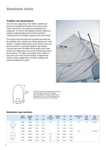
Aluminium mastsTradition and developmentFrom the very beginning in the 1960’s, Seldén produced a comprehensive range of aluminium yachtmasts. Since then, the range has developed andexpanded. The seven new keelboat sections feature awealth of sophisticated and functional solutions,originating from the dinghy range and the yacht range.The sections are extruded and anodized and they areall available with a tapered top. When tapering the mastsection, a wedge shaped piece of the section is cut outand the section is squeezed together and welded.This process does not affect the strength of the mastsection as it takes place prior to the hardening processof the section. The taper is parabolic which means ithas a fair curve over its entire length. A tapered topresults in lower weight aloft, with less windage andimproved response to gusts.Length,mmA Mast ID number is engraved into the lowerend of the mast section, for exampleD14-C126-0584. This mast is made from aC126 section. This is vital information whenlooking for maste parts in this catalogue.Width, mmAluminium mast 9431.3323.33Sail groove,mmBoltrope,Ø mmSailsliderArt. no.4.510511-601XYX105.0511-602
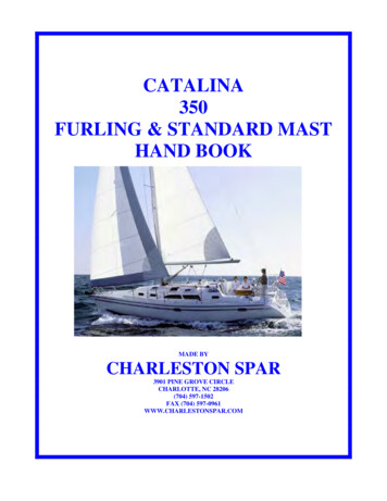
11Photo: Billy Black. CW Hood 32.
Carbon mastsThe future is black and beautifulAll Selden carbon masts use custom designed laminatesto suit the particular application. The combination ofmeticulous care, long experience and exact specifications enable us to achieve optimum performance forminimum weight. The purpose is to make eachindividual boat go faster.The main characteristic of a carbon mast is the highlongitudinal and lateral stiffness in relation to weight.The stiffness is customised to suit each individual boatand the crew can fine tune the prebend and the forestaytension to achieve a higher precision in the sail trim.The weight of a carbon mast is considerably lower thanthe equivalent aluminium section. When designing anew boat, the designer has the option to select a lighterkeel for the same righting moment as when using analuminium mast. Alternatively, he keeps the standardkeel and gains righting moment, a great advantage for ashort handed crew with no crew members on the windward rail.Seldén use unidirectional carbon fibre, pre-impregnatedin epoxy for optimum resin content. Black pigment in theepoxy protects against UV radiation damage andpreserves the mast appearance. The carbon tows arewound around a mandrel producing a seamless uniformquality masts. During the design process the positionand alignment of each fibre is precisely calculated so asto meet the required bend characteristics. Our CNCwinding process makes for high repeatability, animportant issue when producing one design masts. It isa highly developed and efficient process when compared to older manual processes such as female moulding.In addition to the base laminate, Seldén apply localreinforcement as required e.g. in areas for cut-outs oralong the front edge if further stiffness is requested. Thelaminate is compressed and cured by the means ofvacuum, pressure and heat in an autoclave making itcompact and light. The cured tube is separated from themandrel and fitted out to customer specification. Mastscan be clear coated or painted as required.Carbon fibre masts from Seldén are characterized bytheir “viper” pattern. Feared by the opponents,appreciated by winners.Carbon mast sectionsMastsectionSectiondim. incl.track,mmEIy(GNmm2)EIx(GNmm2)Wall thickness, mmWeight,kg/mWy cm3Wx cm3BoltropeSail sliderArt. 337-4426-3110511-602YXThe above table shows data for typical Selden sections using ourstandard tracks. CC077-CC095 use our PVC extruded bolt rope trackas standard, CC105-CC138 use our aluminium extruded track. Othertrack options are available for particular applications.12Seldén use standard modulus carbon fibre as standard for mast sectionsand boom sections. For special applications, please consult Seldén ifhigher specifications material is required.
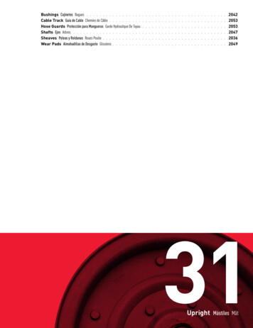
Carbon boom sectionsBoomsectionSectiondim., mmEIy(GNmm2)EIx(GNmm2)Wall thickness, mmWeight,kg/mWy cm3Wx 15Photo: Olivier Blanchet. Heol 7.4.13
Head box, fractional rigThe head box is manufactured from an extrudedaluminium section and prepared for a variety offunctions. An integrated groove in the top edge ofthe head box fitting helps in the installation ofinstrument brackets and backstay flicker, see page 16.To reduce the weight, the head box has four lighteningholes.Head boxes for un-tapered sections, with back stayMast sectionArt. 265Clevis pin forback stayBack stayMax. dia.,mm(wire)MainhalyardMax. dia.,mm (rope)8Dim.,mmArt. no.6165-00548165-1135758590Head boxes for tapered sections, with back stayMast sectionArt. andard head boxLong head box336422Long head box withblock attachment formasthead spinnaker403Standard head box377Long head box504Long head box withblock attachment formasthead spinnaker448Standard head box448Long head boxLong head box withblock attachment formasthead spinnaker594529BB,mmCarbonC087: 58CC086: 45C096: 52CC095: 40C087: 149CC086: 135C096: 143CC095: 130C087: 99CC086: 85C096: 93CC095: 85C106: 70CC105: 55C116: 63CC115: 50C106: 180CC105: 165C116: 173CC115: 160C106: 105CC105: 90C116: 99CC115: 84C126: 83CC125: 70C139: 74CC138: 60C126: 212CC125: 195C139: 203CC138: 190C126: 127CC125: 112C139: 118CC138: 10365Clevis pin forback stayBackstayMax dia.,mm(wire)MainhalyardMaxdia., mm(rope)8Dim.,mmArt. no.6165-00548165-11359075701008085120100
BBMinimum 100 mmAALong head box with block attachment for mastheadspinnaker.Head box, no back stayMast sectionArt. no.Weight, grMain halyardMax. dia., mm (rope)C080-C106501-101-011368Photo: www.sail-box.ch. Mocean.15
Accessories, fractional rigMast sectionAluminiumCarbonBracket forinstrument andlightsArt. no.C080 – C139CC077 – CC138508-303-01Tricolourlight, incl.screws,Art. no.Tricolour light anchor light,incl. screws,Art. no.Bracket for Windexor VHF antennaBackstay flicker1200 x 20 mmArt. no.Art. no.526-020-01526-021-01508-334-01*511-120-03* cannot be combined with backstay flickerBackstay flickerThe bolt heads locate in thehead box grooveLightening holeStainless bracket distributesthe load on the mast sectionThe backstay flicker lifts the backstay to avoiddamage to the leech of the sail when gybingand tacking.16508-303-01Bracket for instruments and lights (Ø 65 mm).508-334-01Bracket for Windex or VHF antenna
Head box, masthead rigThis head box fitting is also manufactured from anextruded aluminium section. It is mounted with a 15 angle and features two sheaves forward for jib/genoahalyards and two aft sheaves for main halyard andtopping lift.Spin Block Loop, art. no. 508-175-01Halyard lead,art. no. 508-159-01Halyard exit,art. no. 505-017-01Accessories, Masthead rigMast sectionArt. 8-01Mast sectionAluminiumCarbonC126 – C139CC125 – CC138979HalyardMax.dia., mm(rope)Forwardsheaves,Aftsheaves,Art. no.Art. no.8504-326(Ø 70 x 13 mm)504-324(Ø 57 x 13 mm)Loop forspinnakerhalyard blockArt. no.HalyardleadArt. no.Halyardexit forspinnakerhalyardArt. no.FurlexhalyardboxArt. no.508-175-01508-159-01505-017-01505-072-01Bracket for Windex oranchor lightArt. no.Bracket for Tricolour light,incl. screws,Art. no.Instrument base508-549-01(20 x 30 mm)508-560-01(60 x 30 x 63 mm)508-563-01(100 x 40 mm)Art. no.Forestay toggles and back stay togglesWire dia., mmArt. no.Clevis pin dia., mm3517-001-0264517-001-018517-002-01105617
Forestay attachments and halyard routing, fractional rigBacking plate for T-terminalHalyard boxThe most common type of forestay attachments is aT-terminal in the top end of the wire and a backing platein the mast. The backing plate is located inside themast so the rig load is properly distributed on the mastsection. The middle part of the fitting protrudes throughthe section forming the female part in the forestayattachment. The forestay has full articulation, whichensures correct alignment and provides a secure andlow fatigue attachment.All boxes are made of a glass fibre reinforced polyamide composite. When used for a spinnaker halyardcoming straight out of the box, Seldén supplies a stainless wear guard. This protects both the halyard and thebox. Halyard boxes combined with Ø 3-5 mm forestaysare available both with plain bearing sheaves as well asball bearing sheaves.Seldén offers three basic systemsSystem ASystem BSystem CUpper sheaveboxSpin halyardSheaveboxSpin halyardSingle Spin Box Guard”ISP”FH (fore triangleheightTwin Spin LeadSingle Spin LeadBacking plateSheaveboxGenoa halyard18
System AForestaydia.,Ø mmBackingplateHalyard box withwear guard forspinnaker halyard,plain bearing sheave.Art. no.Halyard box withwear guard forspinnaker halyard,ball bearing sheave.Art. no.Halyardbox for jibhalyardArt. 51-015507-552-016507-560-01--505-072-01Halyard box with wear guardSystem BForestaydia.,Ø mmBackingplateHalyard box forspinnaker halyard,plain bearing sheave.Art. no.Halyard box forspinnakerhalyard, ballbearing sheave.Art. no.HalyardleadArt. no.Halyardbox for jibhalyardArt. 5-072-01Single halyard leadSystem CForestaydia.,Ø mmBackingplateArt. no.Upper Halyardbox for spinnakerhalyard, plainbearing sheave.Art. no.Lower Halyardbox for spinnakerhalyard, plainbearing sheave.Art. no.Lower Halyardbox for spinnakerhalyard, ballbearing sheave.Art. no.DoubleHalyardleadArt. no.Halyardbox for jibhalyardArt. 4-01505-061-036507-560-01-505-072-01Double halyard lead19
Three functions in one fittingWith a Triple combi box the sheaves for the spinnakerhalyard and the jib halyard are combined with theforestay attachment. This fourth system is available formast section C106 - C139. The exits for the halyardsare well rounded to prevent wear. The sheave for thespinnaker halyard is of larger diameter than the sheavefor the jib halyard. This separates the halyards insidethe mast and makes for smooth low friction operation.Triple-combi boxForestay dia.,mmTriple-combibox,Art. no.Spinnakerhalyard,max. dia., mm(rope)Jib halyard,recommendeddia., mm(rope)Halyard leadfor FurlexArt. no.4-5505-011-01108-10508-159-01Triple Combi BoxSpinnaker halyardFH (Foretriangleheight)PinLead (Furlex halyard)Båtfoto20Photo: Fiona Brown. Quarter tonners.
Halyard routingHalyard boxesWell thought out routing of halyards not only reducesfriction, but will also prolong rope life. It makes for safeand fast sail setting and dousing, equally important forthe cruising sailor as well as for the racing sailor. It’s allabout quick and controlled sail handling.Seldén halyard boxes for halyards and spinnaker lift aredesigned to satisfy very high demands for functionality,strength and light weight.Halyard leadThe single halyard lead guides the halyard vertical andinto the halyard box. It prevents chafe on the halyardand on the halyard box. The location of the halyard leaddetermines the maximum spinnaker hoist. The Seldénhalyard lead is U-shaped, hence it can be retrofittedwithout pulling out the halyard from the mast. Thematerial is chromed bronze which is kind to a wirehalyard. Of course, the lead works well with ropehalyards too. Two halyard leads can be fitted side byside to handle two halyards.Halyard routing is particularly important when a jibfurling system is fitted. It prevents the halyard wrappingaround the luff extrusion when furling or unfurling thesail. A so called halyard-wrap can seriously damage thefurling system, the forestay and the halyard.0 210 mm5-1QWHalyardThe double halyard lead fitting consists of a stainlessbracket with two integrated stainless rings. The brackethas the same radius as the front of the mast. The ringsare well rounded and have flared entry/exit for minimumfriction, promoting fast spinnaker handling.EDouble halyardHalyard exitA halyard exit is used to lead the halyard out of themast and further down to a cleat or a block at decklevel. The fitting prevents chafe between a halyard andthe cut-out in the mast. The location of exits is a veryimportant factor in smooth and effective halyard routing. They must be located with a certain distance fromeach other, not to weaken the mast and at the correctheight for effective sail hoisting. Seldén has a standardset-up for halyard slots, but we will incorporatecustom solutions to suit to a specificdeck layout.To prevent corrosion, all fittingsmade of bronze or stainless steelare insulated from the aluminiummast section. With carbon fibremasts the insulation protects thefittings from corroding.RHalyard exit21
TYArt. no.505-061-03UArt. no.505-061-10IArt. no.505-061-12OArt. no.505-061-16PArt. no.505-072-01Art. no.505-079-02{}Art. no.505-098qArt. no.508-477-01wArt. no.508-502-01Halyard leads, halyard boxes and halyard exitsArt. no.DescriptionApplicationWeight,grMax.rope dia.,mmSafeworkingload, kNMax. RM at30 . kNmTo becombined withforestay dia.,mmFasteners includedSpinnaker, jiband genoa6712---2 pop rivets 167-004(Ø 6.4 x 12.7 mm) andinsulating washer.67----Ø 5.3 mm drill-bit, selftapping M6 skruv andinsulating washer.Q508-159-01Single halyardlead in chromedbronzeW508-159-03Single halyardlead in chromedbronzeE508-734-01Double halyardlead in stainlesssteelSpinnaker18212---4 pop rivets 167-004(Ø 6.4 x 12.7 mm)R505-017-01Halyard exit instainless steelHalyard,spinnaker lift428---1 pop rivet 167-007(Ø 4.8 x 9.9 mm). Thefitting must be laqueredfor insulation.T505-061-03Composite box.Ø 35 mm plainbearing sheaveSpinnaker, jiband genoa508616.03-52 pop rivets 167-006(Ø 4.8 x 16.5 mm)Y505-061-10Composite box.Ø 35 mm ballbearing sheaveSpinnaker, jiband genoa91U505-061-12Composite boxwith chafe guardin stainless. Ø 35mm plain bearingsheaveSpinnakerhalyard,spinnaker lift85I505-061-16Composite boxwith stainlesschafe guard.Ø 35 mm ballbearing sheaveSpinnakerhalyard,spinnaker lift126O505-072-01Composite boxwith Ø 45 mmplain bearingsheaveSpinnaker, jiband genoa94128-62 pop rivets 167-004(Ø 6.4 x 12.7 mm)P505-079-02Stainless box.Ø 25 mm ballbearing sheaveSpinnaker liftfor mast sectionC080- C0874551--2 pop rivets 167-007(Ø 4.8 x 9.9 mm){505-098-03Stainless boxØ 35 mm plainbearing sheaveJib halyard1198816.04-62 pop rivets 167-006(Ø 4.8 x 16.5mm)505-098-06Stainless boxØ 35 mm plainbearing sheaveJib halyard159508-477-01Stainless loopfor attachment ofblock 403-101-01Externalspinnaker lift.Mast sectionC080-C09616----3 pop rivets 167-018(Ø 4.8 x 12.7 mm)508-502-01Stainless loopfor attachment ofblock 404-101-01Externalspinnaker lift.Mast sectionC106-C13935----3 pop rivets 167-004(Ø 6.4 x 12.7 mm)}qw222 pop rivets 167-006(Ø 4.8 x 16.5mm)
2350 mmSPINNAKER HALYARD 22050 mmMAIN HALYARDMAIN HALYARD1750 mmSPARE HALYARD1600 mmGENOA HALYARD1900 mm1750 mmSPINNAKER POLE LIFTSPINNAKER HALYARD 12200 mm2050 mmGENOA HALYARD1900 mmSPARE HALYARD2350 mmSPINNAKER HALYARD 12200 mmSPINNAKER HALYARD 2STBDPORTSTBDPORTSPINNAKER POLE LIFT1600 mmLower edge ofsection or top of coatLower edge of sectionor top of coatStandard layout, C080, CC077Standard layout, all ropes to cockpitFor these small sections no slot fittings are used.A 50 x 8 mm cut-out is thoroughly chamfered toprevent chafe on the halyards.C087-C139, slot fitting 505-017-01CC086-CC138, slot fitting 505-017-51SPINNAKER HALYARD 2MAIN HALYARDSPARE HALYARDLocation of halyard exitsAluminium masts and carbon fibre mastsSTBDPORT2350 mmSPINNAKER HALYARD 12050 mmGENOA HALYARD1750 mmSPINNAKER POLE LIFT2200 mm1900 mmThe standard Seldén layout of the halyard exits isbased on long experience of how to handle halyards,and other parts of the running rig, in the most efficientway. Amongst other things, we assume that the mastman prefers to stand on the starboard side of the mastwhen hoisting the spinnaker and adjusting the spinnaker lift. As exceptions do occur, we can adapt ourstandard arrangements to suit specific deck layouts.1600 mmWINCH PADMAIN600 mm600 mmWINCH PADGENOACLEAT270 mm270 mm270 mm270 mmCLEATLower edge ofsection or top of coatStandard layout, main halyard and genoahalyard to be handled at the mast.C106-C139, CC105-CC138Slot fitting art. no. 505-017-01Cleat art. no. 511-016-01Winch pad art. no. 523-043-0123
24Photo: Karin Herrström. H-Boat.
Spreaders and spreader bracketsAluminium sections C080-C096 and carbon CC077CC095 feature external stainless spreader brackets.These fittings feature a wide base to transfer spreaderloads to the mast extrusion. This makes for a rigidconnection, low windage and low weight.The spreader brackets are angled 6 for optimum rig support.C080; CC077With the clevis pin vernier adjuster system, the spreader angle can be set anywhere from 0 to 34 , with adjustmentincrements as small as 2 . This allows rapid and repeatable tuning to suit weather conditions.Mast sectionAluminiumCarbonSpreader bracketstarboard andport side, Art. no.Alu. /CarbonC080CC077522-168-01/-51Width ofspreader,mmSpreaderangleP-350 – 34 Length,mmPair of spreaders excluding end plugs,Art. no.End plug,Art. no.Blue 00-801-01C087–C096; CC086–CC095This is a larger and stronger version of the vernier adjust type listed above, but with fixed angle spreaders. This isoften required to comply with individual Class rules. Spreaders are custom made to give the correct sweep.Mast sectionSpreader bracketstarboard andport side, Art. no.Alu. /CarbonWidth ofspreader,mmSpreaderangleP-500 - 19 0 - 15 86522-169-01/-51C096CC095522-170-01Length,mmPair of spreaders excluding end plugs,Art. no.Silver anodisedBlack anodised250503-730-01503-610-0120 - 30 300503-731-01503-611-0116 - 30 03-749-01503-629-01End plug,Art. no.500-545-0125
C106 – C139; CC105 – CC138This type of spreader bracket is a through-bar design which provides strength as well as a smooth and elegantappearance. The shroud fittings for the lower shrouds are integrated into the spreader bracket. This reduces thenumber of fittings on the mast, minimising weight and windage.Mast sectionSpreaderbracketstarboardand portside,Width 2-174-01Spreaderangle0 - 30 mPair of spreaders excludingend plugs,Art. 1-1350503-168-01-1400503-169-01-End plug,ClampedArt. no.Linked endplug,Art. no.500-629-01500-630-01Clevis pins for spreader bracketsMast sectionSpreaderWidth ofbracket star- spreader,board andmmport side,Art. no.Alu. /CarbonInner clevis pin,mmOuter clevis pin,mmSplit ringSplit pinArt. no.AluminiumCarbonØLArt. no.ØLArt. no.Art. no.C080CC077522-168-01/-51P-354.7514165-608M5 boltM5 nut-155-049158-004301-527(Ø 10 x 1.5 528(Ø 15 x 73-01C139CC138522-174-01522-170-01UEL Un Equal LengthT-60301-049(Ø 2.9 x 16/19UEL)LØ26
Jumper arrangementA jumper arrangement is a pair of spreaders in the top of the mast, angled 20 forward. Jumpers increase the longitudinal and lateral stiffness of the mast, and are sometimes required if a high hoist gennaker/spinnaker is used, or tostabilize the head of the mainsail.Mast sectionJumperWidth of Length,bracket,spreader,mmstarboardmmand portside, Art. no.Alu. /CarbonPair of jumpers incl.end plugs,Art. no.BlueBlack503-758-11503-784-11Pair of jumpers excl.end plugs,Art. no.SilveranodisedClevis pin,(mm)Art. no.Split ring,Art. no.End Plug,clamped,Art. no.165-607(Ø 4.7 x 8.9)301-527(Ø 10 x 1.5)500-801-01(for Ø 2-3mm wire)165-105(Ø 8 x 32)301-528(Ø 15 x 1.5)500-545-01(for Ø 3-6mm 95522-200-01/-51P-35Cut 3-730-01 503-610-01300503-731-01 503-611-01350503-732-01 503-612-01400503-733-01 503-613-01450503-734-01 503-614-01500503-735-01 503-615-01P35 Jumper arrangementAngle 20 fwdStainless steelP50 Jumper arrangementAngle 20 fwd27
Attachment of the lateral riggingThe attachment for a running backstay or check stayis a backing plate with a securing strap. The strapensures that the unloaded lee-ward stay does notdisengage from the backing plate.Running backstayBacking plateBacking plate including securing strapSecuring strapCheckstayWiredia., mmAluminium mastArt. no.3507-553-024507-551-025Carbon mastArt. no.T-terminal507-553-52507-551-52507-552-02T/Eye toggle for low weight rope runnersRope runners make for lower weight as wellas less chafe on mast and sail compared totraditional wire runners.Wiredia., mmArt. no.3174-1364174-1375174-138T-terminal 26.1tWhen replacing traditional wire runnerswith lightweight runners, in for exampleHMPE, keep your existing backing plateand add a T/Eye toggle.Lower shrouds attached to through bar spreaderbracket. C106-C139, CC105-CC138Shroud attachmentsThe lower shrouds are attached to the mast with a backing plateif the spreader bracket is an external type. For a mast withthrough bar spreader brackets, the aft lowers are fitted in thebrackets and the forward shrouds in separate backing plates.Wiredia., mm28Backing plateArt. no.Aluminium/CarbonMin. mast C1166507-600-01C1267507-601-01C139Location of thelower shroud belowthe spreaderbracket, mm180Lower shroud attached with backing plate.C080-C096, CC077-CC095
Attachments of lower diagonalsWhen using a GNAV the lower part of the mast issupported by lower diagonals. The attachment pointis a stainless bracket on the front side of the mast.Read more about GNAV at page 50.Wiredia., mm34Aluminium,mast sectionC080-C139Art. no.518-081-01Wiredia., mm3518-078-014Lower diagonalsCarbon,mast sectionArt. -CC138518-078-01GNAVPhoto: G-Force Yachts. Xtreme 25.29
Sail entryThe sail entry is a smooth stainless fitting and acceptsboth bolt rope and sliders. Combined with a prefeederfitted to the boom bracket, hoisting a sail with bolt ropebecomes really smooth. For sails with sliders, a springloaded feeder is inserted in the luff groove.The feeder allows for the sliders to pass the sail entryand all the way down to the boom bracket when the sailis reefed or doused. To select the correct size slider,please see page 10.Sail entry505-533-01Spring loadedfeeder for sliders505-534-01600Pre-feederfor luff rope505-538-01Top ofBoomFeeding a sail with sliders1) Feed all sliders into the sail entry.2) The sliders will pass thesail entry all the way down tothe tack.3) The sliders always connectthe sail to the mast, simplifying hoisting and reefing.Feeding a sail with luff rope1) Tie the pre-feeder to the boom bracket.302) Feed the luff rope into the sail entry.3) Hoist the mainsail.
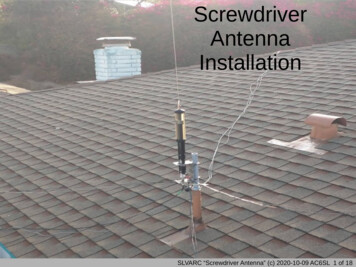
Deck-stepped mastsLoad distributionA convex heel plug at the lower end of the mast sectionallows the mast to be raked 3,5 aft and 1 forward, andstill evenly transfer compression load to the mastsection. This concept is far from new but nevertheless,brilliant. It was introduced by Seldén early 70’s.3.5 1 Convex heel plug distributes compression load evenly on themast section.It is easy to step the mastThe aft end of the heel plug is connected to the T-basewith a clevis pin. This clevis pin works as a hinge andallows for controlled raising and lowering of the mast, agreat help for sailors who frequently un-step their mast.For the owner of a trailer boat the advantage is obvious.31
T-base, heel and attachments for deckblocksRopes leaving the mast through halyard exits continuedown and then lead aft to clutches, Cam cleats orValley cleats located within reach of the crew in thecockpit. The mast stands on an aluminium T-base,which is bolted to the deck. Six stainless attachmenteyes, three on each side, can be fitted between theT-base and the deck for attachment of lead blocks.This enables ropes to be efficiently routed to thecockpit. In addition, the T-base comes with two centreline attachment loops, one forward and one aft. Theseloops are mainly used for spinnaker pole downhaul andthe kicking strap.T-baseLoop for spinnakerpole downhaulAttachment eye forhalyard blockMast heelMast heel without sheavesMast sectionAluminiumCarbonC080CC077Heel plug,Art. no.T-base,Art. no.Attachmenteye,Art. no.Loop,Art. no.LmmWmmAmmBmm502-560-01 510-158-01--100351040502-560-02(sheaves) 510-155-01--15040744 2-566-01(adjustable) 510-171-01**Including attachment eyes and loops.QWT-BaseLAREARDWVerAsion 4DECK HSELDÉNBACDECKHARDWARELWB32T-Base, attachment eye and loopLWBERAdjustable T-baseBCWAB1Read more about Seldén’s blocks,Cam cleats and Valley cleats in ourDeck Hardware catalogue, art. no.595-905-E.Attachment eye,Art. no. 508-497Loop,Art. no. 508-459
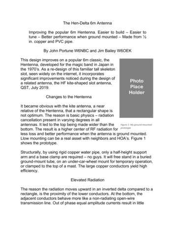
Mast heel with integrated sheavesHalyard ExitsAn alternative to halyard exit slots is to run the halyards outthrough the mast heel. Seldén offers this solution by adding afitting with four integrated sheaves between the mast sectionand the heel. The sheaves are fitted in adjustable cages that canbe individually angled towards a deck organiser or direct to aCam Cleat in the cockpit area. In the top of the stainless cages,rubber o-rings preserve the cage alignment when the rope isunloaded. They also prevent rattling.70 SpinnakerhalyardSpinnaker liftJib halyard90 Main halyardBall bearing sheaves are available for some of the sections.When needed, additional attachment eyes and loops can befitted underneath the T-base.Mast heel with sheavesMast sectionMast heel with fourplain bearingsheaves, Art. no.Mast heel with fourball bearing sheavesArt. no.Aluminium/CarbonHeight of ropesabove -C139CC138502-566-02/-52-522 sheaves each side.Stainless holder,70-90 articulationRubber O-rings toprevent rattling.Hinged heel plug as standardLoop for spinnaker poledownhaul attachmentLoop for kickerattachmentEyes for block attachments33
Keel-stepped mastsThe aluminium deck ring comes with six stainlessattachment eyes, three on each side. Blocks forhalyards are attached to the eyes to lead ropes back tothe cockpit. There are also two stainless loops fitted tothe deck ring, one forward and one aft. These are intended for the spinnaker pole downhaul and kicking strap.A keel-stepped mast has, as standard, an internal sealin order to minimise water leaking into the bilge. Thecable conduits are open to simplify installation ofadditional cables but they can be sealed afterwards ifrequired. Externally, a flexible mast coat prevents waterleaking through the deck.The mast is secured in the deck ring by rubber wedges.To prevent lifting the deck by the halyard loads, Tierods are fitted in backing plates in the mast section andconnected by rigging screws to attachment loops in thesolid deck laminate.Deck ringMast sectionT-Base,Art. no.Deck ring includingattachment eyes,loops, backing platsfor Tie-rods andrubber wedges,Art. no.Mast coat,Art. no.Hose clip,Art. no.Attachmenteyes,Art. no.Loops,Art. no.Rubber wedges,Art. 42 x 530-2391 x 530-240C139CC138-530-0652 x 530-239533-034-01530-063312-202508-497508-4592 x 530-2392 x 530-240Drainage holeMast coatTop of Deck220Tie rod backingplateTie rod arrangementDeck ringRubber wedgesSail grooveMast section34Cable conduit
U-baseMast -base,Art. no.510-178-01LmmWmmAmmBmm1808550120Convex top.U-base 510-178-01
Carbon mast sections The above table shows data for typical Selden sections using our standard tracks. CC077-CC095 use our PVC extruded bolt rope track as standard, CC105-CC138 use our alum