Transcription
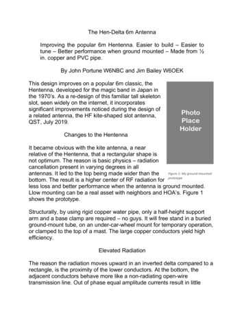
ASSEMBLY INSTRUCTIONSfor Fiberglass Telescoping / Push-Up MastsAll mast kits (“MK”) include telescoping fiberglass tubes and corresponding quik-clamps
ABOUT OUR MASTSThe Max-Gain Systems’ Fiberglass push-up masts are made of the highest quality pultruded fiberglass tubingand with a massive 1/8 inch wall thickness. The Quik-Clamps we designed to use with our fiberglass tubinguse a proprietary stainless steel reverse double helix screw and matching nylon thumb lever to create greatholding power while being extremely easy to use. Our fiberglass mast kits are available in 10 differentmaximum height configurations. The desired height can be achieved for your application by using less of themast sections (not extending each section so far out) or by removing sections altogether and using morelength of the larger tube sections.Notice: No fiberglass mast in the world, (and few, if any, steel masts of these heights) are designed towithstand multiple wire antenna loads or any rotational loads. NO rotators or “rotors” should be mounted on ourmasts! Our masts are not designed to support HF beams. They are well suited for support of light wireantennas, small, light, VHF and UHF antennas (even small VHF and UHF beams in fixed-position use. again,no rotators), small cell phone and wifi boosters, light camera equipment, and other attachments. Handrotation* is possible with our guy rings as they “float” over the “quik-clamps”. Remember that the coax cable orfeed line is part of the weight to be supported by the mast and must be considered as part of the weight of theantenna. Be reasonable in your expectations and careful in guying and erecting your mast, and it will serve youwell!Demonstrating Hand Rotation*Leverage experienced with tall structures will make them impossible to hold at anangle, so again, keep the structure vertical at all times during extension andretraction (DO NOT extend the mast on the ground and “walk it up”). Havingpeople on all guy ropes to maintain control (keeping the structure VERTICAL atall times) during raising or lowering the structure is a must. When letting thestructure down, be certain to maintain a firm grip on the inner tubes when youSLOWLY release tension on the thumb clamp. Do not rely on the clamp tensiononly to let down each section. Gloves (selected for a good grip on the tubesurface) will be a BIG help. Always raise and lower in adequate lighting to avoidaccidentally extending the mast past the “stop” line you marked on the tubes.Again, ALWAYS have adequate help on hand to maintain control of the structurewhen raising or lowering.POWER LINE CAUTIONSEven though your new mast is a non-conductor, (and as a result is MUCH safer in many applications thanmetal masts) do not get a false sense of security if near power lines. Remember that even if you use thenon-conductive Dacron guy ropes and our guy rings that we recommend, (which are also non-conductive) theitems that you are supporting (such as wires, metal antennas, cameras and control cables, and coaxial cablesand wire feed lines) ARE conductive. If these components of your installation come in contact with power lines,they can KILL. The insulation on coax cable or most control cables is only rated for a few hundred volts, andyou may find THOUSANDS of volts present on power lines. DO NOT INSTALL IN CLOSE PROXIMITY TOPOWER LINES. Should a power line somehow come in contact with any part of your installation, alwaysconsider it to be energized, and dangerous. Do not touch any part of your installation and call the powercompany immediately for help.
MAST KITS AVAILABLEWe have ten mast kits available. Ranging from as short as 10.4 feet when fully extended, that could fit in aluggage bag, up through the 50 foot tall MK-8-HD mast.See the chart below:MaximumPartUsableNumberLengthMK-8-HD50 feetMK-6-EXT43.3 feetMK-6-HD38 feetMK-6-STD32 feetMK-4-EXT28.5 feetMK-4-HD25 feetMK-4-STD21.5 feetMK-2-EXT14 feetMK-2-HD12.1 feetMK-2-STD10.4 feetLengthwhensleeved9 feet5 inches7 feet10 inches7 feet7 inches7 feet2 inches5 feet8 inches5 feet6 inches5 feet1 inch3 feet10 inches3 feet7 inches3 feet3 inchesMinimumoverlap oftubes8.5 inches8 inches8 inches8 inches4.25 inches4.25 inches4.25 inches3 inches3 inches3 hes23.25inchesOD ofbottom tubesectionOD oftop tubesectionNumberofSectionsWeight2.5 inches1 inch722.6 Lbs2.5 inches3/4 inch818.9 Lbs2.5 inches1 inch717.8 Lbs2 inches3/4 inch611.8 Lbs2.5 inches3/4 inch812.75 Lbs2.5 inches1 inch712 Lbs2 inches3/4 inch67.9 Lbs2.5 inches3/4 inch87.2 Lbs2.5 inches1 inch76.75 Lbs2 inches3/4 inch64.4 LbsWhen selecting a mast, do not just look at the maximum usable height. Be sure to take note of the differencesin the different models. The HD and EXT have a bottom tube section starting at 2.5 inches where the STDstarts at only 2 inches. These diameter differences are very pronounced when trying to figure out what youwant to support by the mast. The STD models have a piece of 3/4 inch tube at the top making it ideal forsupporting things like a vertical wire antenna whereas the HD models have a 1 inch top section which is muchmore stiff than the 3/4 inch tube. This allows for greater rigidity and allows for support of more robustequipment. Tube length also makes a difference when deciding as a shorter piece of 3/4 inch tube is far morestiff than a longer one (a 46.5 inch piece in the MK-4-EXT would be less flexible than the 72 inch piece in theMK-6-EXT). All of these factors need to be considered when selecting a mast for your application.LEVER LOCK “QUIK-CLAMPS” (TELESCOPING TUBE CLAMPS)Each Mast Kit comes with its corresponding quik clamps. EXT masts come with 7 clamps, HD masts comewith 6 clamps, and STD masts come with 5 clamps. These telescoping tube clamps can also be purchasedindividually on our website: amp-mast-clamps/
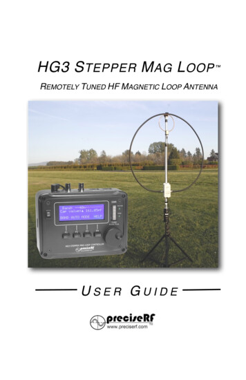
Each clamp is determined by the outer diameter of the tube that the base end of the clamp sits on. If the baseof the clamp sits on the end of the 1.5 inch OD round tube the clamp used is the MC-150. The MC-150 acceptsthe 1.25 inch OD round tube through the top of the clamp which is clamped by the clamping ears.GLUING, GLUES, AND ADHESIVESSurface Prep: Do not clean the fiberglass surface with alcohol, mineral spirits, etc if you wish to clean thesurface, use ONLY a damp towel to wipe off surface dust.When gluing the Quik Clamps, be certain to apply a bead of the adhesive completely around the bottom edgeof the clamp. Smooth the adhesive into a nice fillet as you would if caulking a bathtub. Let dry for a day or two,and you are done!NOTE: If you find a clamp that is not an easy slip fit on a tube end, just get a piece of scrap board, and placethe board on the top of the clamp and tap it into place with a small hammer. Don’t worry the clamps are verytough! Be certain that the clamp is square with the end of the tube and is not tilted. Tilted clamps willcause the fiberglass tubes to bind as they are extended and retracted. (Tight fitting clamps have the advantageof not needing adhesive, as they will not accidentally be pulled off.)Many glues and adhesives are satisfactory since the glue works to prevent the clamp frompulling off as you extend the inner tubes upward. In use, the downward pressure of theweight above keeps the clamps firmly in place. Some clamps may not require any adhesiveas they maybe “tight” to put on the corresponding tube. Glues such as“Goop”, silicone sealer, and 50/50 epoxy (consistency of syrup. notfiller types with putty consistency) will all do the job. JB Weld 2 partepoxy in the Red and Black tubes labeled with “Steel” and “Hardener”on the tail end, which is available in most hardware stores, sets up in afew hours and cures fully in a day or so, applies easily, and works verywell.J-B WELD (Original Cold-Weld Formula)Our favorite adhesive for gluing the Quik-Clamps on our fiberglass tubes is clear siliconeglue, also known as aquarium sealer. Sold under many names such as GE Silicone, DowSilicone, DAP Silicone, this adhesive is widely available at Home Depot, Lowe’s, andhardware stores. Be sure it is fresh, and not an old, previously opened tube, or propercuring is doubtful. To apply, slide the base of the clamp firmly onto the matching size tube. These glues are ourfavorite because if you happen to drop your mast on concrete (yes, it can happen) and break one of the ears ofa clamp. All you will need to do is remove that fillet of silicone from around the base of that clamp then twist theclamp back off of the tube. Some clamps fit tighter than others and some will require more adhesive and somevery little to none, but this method makes all of the clamps replaceable if the need should arise. Using othergluing methods would require cutting the fiberglass tube to remove the broken clamp before it could bereplaced which would also shorten the usable height of your mast by a small amount (about an inch or two).Glues “NOT” to useGlues which expand as they dry, such as“Gorilla Glue” are NOT recommended,because the glue tends to migrate into placeswhere it should not be as it expands. Do NOTuse PVC cement (purple and clear mixture),which works by dissolving PVC and “melting” ittogether. It will NOT dissolve fiberglass and will not work at all. Do NOT use Liquid Nails or any other gluedesigned for gluing wood. These glues will not bond to fiberglass and will only make a mess. Do NOT use“Super Glues”. They cure then become rock hard and brittle.
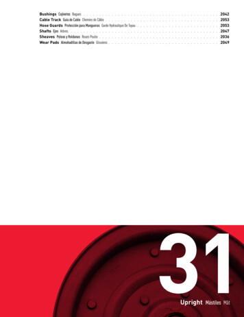
FULLY SEATED CLAMPNOT FULLY SEATED CLAMPAllow enough time for the adhesive you have chosen to dry before proceeding.MARK TUBESThe fiberglass tube sets do not have a physical stop inside each tube to prevent pulling out the tube during theextending process. Use this period to mark the outside of each tube (except the bottom one) with a contrastingcolor band for a visual stop. A black magic marker will work nicely on the gray tubes. Do NOT try to “cheat” alittle on these recommended overlaps to gain a little extra height. These overlaps are ABSOLUTE MINIMUMS.Greater overlaps only make your mast more rigid if maximum height is not required.Mark placement is a crucial step in order to ensure you are staying within safe operating ranges.See the following chart which details, for each mast, the point from one end of each tube at which to place themark all the way around the tube. Your model of mast will determine the point for each tube where to makeyour mark:Part DMK-4-STDMK-2-EXTMK-2-HDMK-2-STDDistance from one endof each tube10 inches9.5 inches9.5 inches9.5 inches5.75 inches5.75 inches5.75 inches4.5 inches4.5 inches4.5 inches
ADJUSTING CLAMP TIGHTNESSAfter the Quik-Clamps are cured, you can then raise the thumb-clamp levers and insert the tubes within oneanother. You will notice a screw in the clamp. This screw is used to adjust the tension of the clampingmechanism. With a Phillips tip screwdriver, (be certain to use a large enough Phillips screwdriver to properlyengage the large screw slots. (Preferably a #3 Phillips). Tighten the screw just to the point before it hinderspassage of the inner tube. The screw is REVERSE THREAD, so turn COUNTERCLOCKWISE to tighten.TEST the thumb clamp at that point, and make certain that you have the tension adjusted properly so that youmay extend the inner tube, and that when the thumbclamp is in the “down” position, that the inner tube isgripped FIRMLY. It is most important not to overtighten the screw. The thumb clamps havetremendous leverage, and if over-tightened,something HAS to give. (probably one of the sidesof the clamp “ears”). Try this adjustment a few timesuntil you find the perfect setting. Do not use threadlock compound on the screws. It is not necessary,and thread-lock compound is one of the very fewthings that can attack and weaken the material usedto make the clamps.NOTE: We do NOT recommend painting our pushup masts or extension poles! The inside of thetubes is more abrasive than the smooth outer finishand will quickly scar most paints. Thick paint coatscan also decrease clearances between the tubes,causing them to jam. Count on our high percentageof UV inhibitors in the resin to provide long useful life.We do not recommend using solid rods in theplace of our hollow tubes with our Quik-Clamps.The solid rods are much more difficult for the clampsto hold tightly for several reasons, and if the clampsare over-tightened in an attempt to do so, the clampsmay break. If you feel that you need to use a solidrod at the top of your mast, call or email us to discusssome options that will in fact work satisfactorily.
GUYING INSTRUCTIONSA tall structure such as our full-length model MK-8 or MK-6 series masts (includingthe HD versions) MUST be guyed and kept under control with guys even whilebeing erected. NOTE: Do NOT use metal guy cables with this mast system! Metalcables are conductive and HEAVY and add significantly to the vertical loading ofthe mast. Enlist three friends, family, or neighbors (or 4, if you choose 4 pointguying) to stand in the approximate locations of the guy anchor points, and to holdthe guy ropes and “feed them out” as you extend the mast, all the while beingcertain that the mast stays vertical. We recommend guying at least two levels withthree direction guys.Non-stretch, UV resistant, light, low visibility ropes such as the 1/8” OD blackdouble-weave Dacron rope such as the “Hexrope 4” (1000 foot rolls) or “Hexrope3” (200 foot rolls) that we sell are ideal. If you are not proficient in knot tying, werecommend that you seek tutoring from someone who is OR use a tension deviceknown as a guy rope tensioner.Our specially made guy rings are tough, non-conductive, and UV-proof. Our guy rings are made in seven sizesto fit perfectly on our different tubes (3/4 inch, 1 inch, 1.25 inch, 1.5 inch, 1.75 inch, 2 inch, and 2.25 inch).Having these seven sizes should offer adequate choice of guying position for almost any use. These guy ringsslip on the tubes and rest on the Quik-Clamp beneath. They are drilled for either 3-point guying or 4-pointguying, as you prefer. The guy rope holes are counter-sunk to avoid cutting ropes.Be sure to check out our part number: GUY-TEN-01. These guy line tensionersmake the guying process easy. Attach the ring on the guy tensioner to your groundguy points (one tensioner per guy rope), pull back on the “T-Shaped” portion of thetensioner, which loosens the three ball bearings on the interior of the tensioner.Feed the rope through the opposite end of the tensioner. Grab the body of thetensioner and begin to take up the slack from the rope. Pull to the desired tightness.Each tensioner is rated for a safe working load of 110 pounds!Using the Guy Line Tensioners (our P/N GUY-TEN-01) is a quick and easy way to guy amobile OR a permanent setup!With the Guy Tensioners, if you are not using a mounting point that has a opening to hookthe guy tensioner’s “D” ring to / or even if you are, we offer a pear shaped Quick Link(our P/N QL-NPS-1625) that is ideal to attach the guy tensioners to anyattachment point. This will make a strong, rock solid connection between yourguy point and the guy tensioner.We also have designed Guy Stakes (our P/N GUY-STAKE-23). These stakesare incredibly strong. Made of galvanized steel angle, these stakes can bedeployed numerous times and not bend like most all others out there. Beingmade of angle steel, these stakes bite into an enormous amount of earth unlikethe thin auger type anchors which bend and bow under the stress of guying astructure.Guying shorter masts such as our models MK-4 and MK-6depends on your application, and the item(s) beingsupported. An adequately spaced, at least 2-point clamparrangement on the bottom section may be sufficient formany light duty or partially-extended applications. Whenclamping to fiberglass tubes with U-bolts, be careful not toover-tighten to avoid crushing the tube. When in doubt, guy!Err on the side of over-engineering, never under!
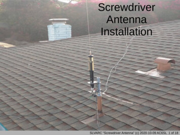
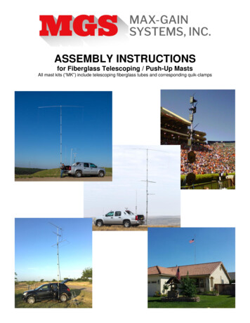
Even with guyed structures, always secure the base in a secure fashion where it cannot move. In semipermanent installations, be sure the bottom tube end is not plugged so that water can drain out. Water canfreeze and split the tube if allowed to accumulate. Guy anchor points should be strong enough to withstand agreat deal of pulling force, and away from the mast far enough that the guy ropes form a 45-degree or greaterangle with respect to the mast. If the guy anchor points are too close to the mast, the guys not only exert agreat deal of downward pressure on the mast, adding to the vertical load, but they have far less mechanicaladvantage on the structure while doing their job of keeping your mast stable during severe environmentalconditions. Final adjustment of your guy ropes should be without excess slack, but not so tight as to “load” themast.Leverage experienced with tall structures will make them impossible to hold at an angle, so again, keep thestructure vertical at all times during extension and retraction. Having people on all guy ropes to maintaincontrol (keeping the structure VERTICAL at all times) during raising or lowering the structure is a must.When letting the structure down, be certain to maintain a firm grip on the inner tubes when you SLOWLYrelease tension on the thumb clamp. Do not rely on the clamp tension only to let down each section. Gloves(selected for a good grip on the tube surface) will be a BIG help. Always raise and lower in adequate lighting toavoid accidentally extending the mast past the “stop” line you marked on the tubes. Again, ALWAYS haveadequate help on hand to maintain control of the structure when raising or lowering.MOUNTINGOur Mast line needed a full array of mounting products that could easily be adapted for any use or situation.For permanent or mobile / temporary use. Not to mention, built to stand the test of time. We have painstakinglydesigned a mounting system that can be configured in multiple configurations. A trailer hitch mount, groundmount, and drive on mount, using most of the same components. The same support tube can be pairedwith one of the plates to make a ground mount or a drive-on mount, use the holes in the center or the holestoward the end of the plate. Pair the support tube with a hitch bar and two of our super tough stainlesssquare U-Bolts to make a hitch mount. We do offer all of these parts as Kits to make it easy to pick. We alsohave a tilt mechanism that will allow for MUCH easier operation of your mast. With a tilt mechanism, you canhave your mast secured in the mounting base and, while the mast is down in the collapsed position, tilt it overand prop your mast up on something to allow for easy access to the top section of your mast to operate onyour antenna, flag, light fixture, whatever you might have on top. The tilt mechanism is operated by a T-Bolt onthe side of the device. You would remove it to tilt it over. All of our mounting products are made using steel thatis laser cut for precise fits and reduced manufacturing burrs that can scratch the fiberglass masts. The mountsare powder coated for durability and to ensure your mount has a nice smooth finish. All of the hardware isstainless to make sure that the mount will be as easily operated as possible for as many years as possible.This mounting system is sold in kits and by the piece so you can make the system fit your needs withoutpaying for any parts you don’t need.Drive-On MountGround MountHitch
HITCH MOUNTDRIVE-ON MOUNT(Hitch mount with 23 inch bar for usewith tailgate)(Drive-on Base Mount)GROUND MOUNTHAND ROTATION CAPABLEAll supporttubes allow formast rotationeven whenguyed usingour guy rings.Just loosenthe clampingears of theverticalsupport tube.Thank you for your purchase!Max-Gain Systems, Inc.150 Dodd Street SEMarietta, GA 30060-2460Phone 770-973-6251fax 815-461-7730email: info@mgs4u.comhttp://www.mgs4u.com
ONE YEAR LIMITED WARRANTYMax-Gain Systems, Inc. (“MGS”) warrants its fiberglass mast products to the original purchaser for a period ofone year from the date of the original end-user purchase, that the mast components (fiberglass tubes andassociated clamps) shall be free of defects in workmanship and materials, under normal use conditions and ifinstalled, guyed, and maintained in accordance with our provided instructions.Exclusions and limitationsThis warranty does not apply to conditions of faulty or improper installation, guying, or maintenance, oralteration in any way that is not covered in the documentation for the product, or if the product is damaged byacts of God, misuse, abuse, negligence, accident, normal wear and tear and deterioration, or lack ofresponsible care, or by any other causes not related to defective materials or workmanship. This warranty doesnot cover any antennas or other equipment mounted on or supported by our product.Applicable lawThis limited warranty is governed by the laws of the state of Georgia, USA.Warranty claimsRequests for warranty adjustments shall be made in writing, (letter or email) to the address or email address shown on theMax-Gain Systems, Inc. website.MGS may, at our option, request return of defective parts. Any and all shipping to and from addresses outside thecontiguous 48 states in the USA shall be the exclusive responsibility of the purchaser. For customer addresses within thecontiguous 48 states in the USA, shipping of any damaged parts to MGS, should we (at our option) request their return,shall be the responsibility of the purchaser. Shipping (via standard ground service) of replacement parts back to thecustomer (within the 48 contiguous states of the USA) is covered under this limited warranty.If a valid claim is received within the warranty period, the sole remedy of the original purchaser and Max-Gain Systems,Inc.’s sole and exclusive liability shall be limited to, at Max-Gain Systems, Inc.’s sole discretion, replacement of thedefective component or replacement of the product, or refund of price paid for the product.The warranties and remedies provided above are exclusive and in lieu of all other express or implied warranties including,but not limited to, the implied warranties of merchantability or fitness for a particular purpose. Certain jurisdictions do notallow the exclusion of implied warranties. If laws under such jurisdictions apply, then all express and implied warrantiesare limited to the warranty period identified above. Unless provided herein, any statements or representations made byany other person or firm are void. Except as provided in this written limited warranty and to the extent permitted by law,neither Max-Gain Systems, Inc., or any affiliates shall be liable for any loss, inconvenience, or damage, including, but notlimited to direct, special, incidental, or consequential damages, resulting from the use or inability to use any Max-GainSystems, Inc. product, whether resulting from breach of warranty or any other legal theory.Notwithstanding the foregoing, Max-Gain Systems, Inc.’s total liability for any and all claims under this limited warrantyshall not exceed the price paid for the product. These limitations on potential liabilities have been an essential condition insetting the product price.
mast sections (not extending each section so far out) or by removing sections altogether and using more length of the larger tube sections. Notice: No fiberglass mast in the world, (and few, if any, steel masts of these heights) are designed to withs