Transcription
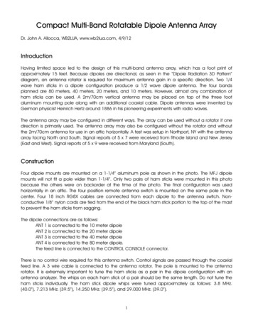
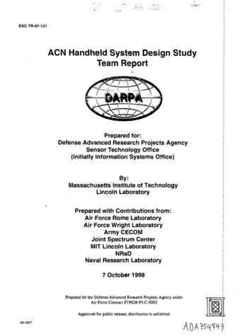
The Hen-Delta 6m AntennaImproving the popular 6m Hentenna. Easier to build – Easier totune – Better performance when ground mounted – Made from ½in. copper and PVC pipe.By John Portune W6NBC and Jim Bailey W6OEKThis design improves on a popular 6m classic, theHentenna, developed for the magic band in Japan inthe 1970’s. As a re-design of this familiar tall skeletonslot, seen widely on the internet, it incorporatessignificant improvements noticed during the design ofa related antenna, the HF kite-shaped slot antenna,QST, July 2019.Changes to the HentennaIt became obvious with the kite antenna, a nearrelative of the Hentenna, that a rectangular shape isFigure 1; My ground-mountedprototypenot optimum. The reason is basic physics – radiationcancellation present in varying degrees in allFigure 1: My ground-mountedantennas. It led to the top being made wider than thebottom. The result is a higher center of RF radiation for prototypeless loss and better performance when the antenna is ground mounted.Llow mounting can be a real asset with neighbors and HOA’s. Figure 1shows the prototype.Structurally, by using rigid copper water pipe, only a half-height supportarm and a base clamp are required – no guys. It will free stand in a buriedground-mount tube, on an under-car-wheel mount for temporary operation,or clamped to the top of a mast. The large copper conductors yield highefficiency.Elevated RadiationThe reason the radiation moves upward in an inverted delta compared to arectangle, is the proximity of the lower conductors. At the bottom, theadjacent conductors behave more like a non-radiating open-wiretransmission line. Out of phase equal amplitude currents result in little
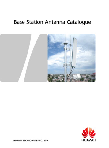
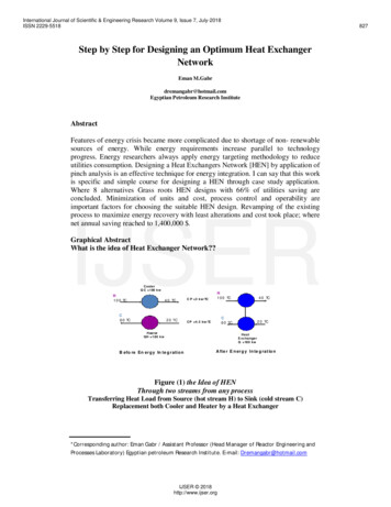
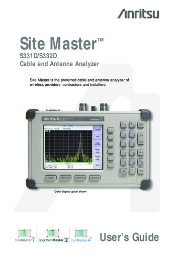
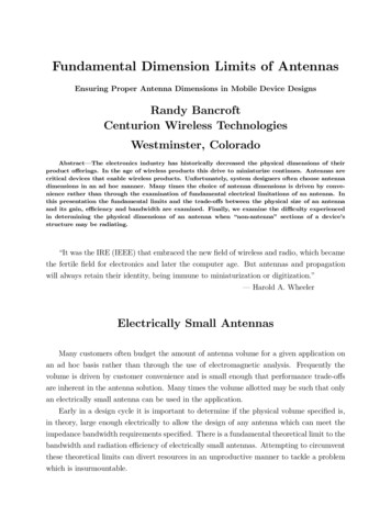
radiation, just as in an open wire line. The EM wave from this antenna,therefore, radiate mostly from the top, horizontally polarized. Also, being talland narrow, like a classic vertical, the radiation angle is low.If you would like to confirm these findings, e-mail W6NBC for an EZNECmodel file: jportune@aol.com. With it, perform an [FF PLOT] and then lookat [CURRENT PHASE] in [VIEW ANTENNA]. There you can see theradiation cancellation and the polarization. For a more-completeexplanation, see chapter 15 of the Amazon/Kindle e-book: Slot Antennasfor Ham Radio.PerformanceFigure 2: Elevation radiation patterns with gainsat 1 ft (blue) and 10 ft. (violet)Figures 2 and 3 showthe comparativeradiation patterns atground level (blue) andat 10 ft over averagesoil (violet).Figure 3: Azimuth (horizontal)Figure 3 shows a further radiation patterns with gains at1 ft (blue) and 10 ft. (violet)benefit, azimuth gain (6dBi when ground mounted).Conventional verticals normally need to be in aphased multi-antenna array to give azimuth gain. The gain here iscomparable to a small beam on a modest tower, with an antenna that is farless visible to the neighbors.Figure 4 shows the 3 dBbandwidth, roughly 1 MHz.ConstructionFigure 5 gives dimensionsand materials. Note themovable fixtures near thebottom (black). These areFigure 4: SWR curvethe adjustments forfrequency and SWR. The coax connects to the ends of the SWR fixture(more detail below and in Figure 8).
Begin by bending 12 in. of one end of two 10 ft. lengths ofType M common ½ in. rigid copper water pipe to the smallangle shown in Figure 5 & 6. Avoid type L or K pipe –unnecessarily heavy. To make the bends, flatten the pipeshalfway with the tip of a large Vice Grip style pliers. Thehalf-flattened spot will then bend neatly over the edge of aworkbench, Figure 6. Next, trim thetotal length of the side sections to 112in, including the bent ends.Figure 6: Bend at halfflattened spot in pipeFor the odd-angle corners at the top,completely flatten 1 in. of the ends ofthe side and top pipes and drill holesfor ¼-20 stainless bolts, washersand nuts.Mast snd Support ArmsFigure 2: Flattened andFor the mast, cut a length of 1½ in. bolted top cornerswhite Schedule 40 or gray Schecule80 PVC pipe suitable for your preferred method ofmounting – mast or ground mount, and two 10 in.lengths of the PVC pipe for the cross arms. Next makea slot across the center of one end of each cross arm,2¼ in. deep by 5/8 in. wide. Cement together the mast,the T coupling and the support arms, being sure thatthe slots point upward.Figure 5: Essential dimensionsand materials.and antenna pipesCut a short 2¼ in. pipe stub to go between the elbowsat the bottom of the delta. Drill a ¼ in. hole through themiddle of the stub for attaching the antenna to the PVCmast. Finally, assemble all the copper pieces on a flatsurface with the bent pipe ends parallel to the mast.Bolt on the top section and solder the bottom short stubInsert the antenna into the slots in the PVC cross arms, adjusting the heightof the PVC cross arm from the bottom for a proper fit, Figure 5. Cement on1½ in. pipe caps to the cross arm ends to complete the support. The cross
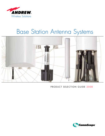
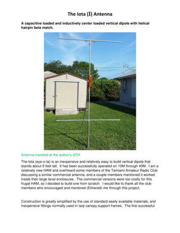
arms will be roughly 60 in. from the bottom. Drill a ¼ in. hole through thePVC pipe at the bottom to match the center hole in the pipe stub. Bolt theantenna to the mast with a 3 in. stainless bolt, nut and washer.Adjustment FixturesThe moveable bars foradjusting frequency andSWR attach to the side pipesby modified ½ in. stainlesswire clamps They areavailable at most electronicsparts stores and on theinternet. Figures 8 & 9 showthe details.These are the clamps that Iused:Figure 9: Moveable adjustment bars forfrequency and SWR.Figure 8: lower sections withfeedpoint (SWR) andfrequency tainless-RubberCushioned/dp/B01N074XSY/ref sr 1 3?dchild 1&keywords 1%2F2 in. stainless wire clamps&qid 1604016706&sr 8-3Remove and discard the neoprene cushoning. Partiallybend open the clamp and them flatten both ends. Reform the clamp around ½ in. copper pipe, bending theends into the shape shown in Figure 10. Electricianspliers and heavy-duty needle nosed pliers work well forbending.The end holes in the clamp should line up asshown.Cut two 2½ in. x 1/8 in. x ½ in. flat bars to connect theclamps. For the SWR (feedpoint) bar, make it of aninsulating material, e.g. plastic. Use aluminum or copperfor the frequency bar. Flattened ¼ in. aluminum orFigure 10: Re-shapedstainless cable clamps forends of adjustment bars.
copper tubing is also suitable for the frequency bar. Drill ¼ in. holes, ½ in.from both ends for ¼-20 in. bolts and nuts.Feedline and BalunPrepare a pigtail of RG-58 or Mini RG-8 with a connector on one end.Separate and fan out roughly 3 in. of the braid (shield) and the centerconductor into separate wires. Add heat-shrink tubing for weather proofingand ring terminals for ¼ in. lugs. For the run into to the shack, use largerlow-loss coax. Small diameter coax has high loss at VHF.Also provide a 1:1 current choke balun at the antenna. It can be acommercially-made unit, several ferrite sleeves, toroids or clamp-on chokebeads, or 6 turns of the coax pigtail wrapped around the PVC mast,secured with holes in the mast and/or zip ties.Tuning and MatchingWith the antenna in a ground mount or temporarily mounted on a nonmetallic support at least 5 ft. above ground, adjust the tuning and matching(SWR) with an antenna analyzer, portable VNA or a transceiver and anSWR bridge. Adjust the match first for a low SWR, paying little attentioninitially to the resonant frequency. Once set, the SWR will change littlewhen you next adjust the frequency. To set the frequency, move both barsas a pair, maintaining the separation. Minor re-adjustment will likely berequired with the antenna in its final location.Good performance when ground-mounted for low neighbor/HOA visibility,,azimuth gain comparable to a small beam, plus horizontal polarizationmake this small vertical a good choice for the magic band, as a permanentinstallation or for portable/field day operation.My sincere appreciation to W6OEK Jim Bailey for his help on this antenna.His keen insight twice destroyed my initial engineering, but the final result isnow clean and easy.
Mast snd Support Arms . For the mast, cut a length of 1½ in. white Schedule 40 or gray Schecule 80 PVC pipe suitable for your preferred method of mounting – mast or ground mount, and two 10 in. lengths of the PVC pipe for the cross arms. Next ma