Transcription
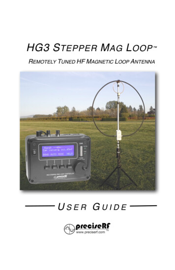
HG3 S TEPPER M AG L OOP REMOTELY TUNED HF MAGNETIC LOOP ANTENNAUSER GUIDE
TABLE OF S - EXPRESS MODEL!11STARTUP - ALL VERSIONS!12TUNING FOR MAXIMUM NOISE - EXPRESS MODEL!13CHECKING THE SWR - EXPRESS MODEL!14CONNECTIONS - PRO AND LAB OPTIONS!15TUNING FOR MAXIMUM NOISE - PRO AND LAB MODEL!15AUTO TUNING FOR LOW SWR - PRO AND LAB MODELS! 16TUNING TIPS!1880 AND 60 METER TUNING!19THE AR-1 ROTOR!20TURNING THE AR-1 ROTOR!20PRECAUTIONS!21SPECIFICATIONS!22SYSTEM REFERENCE!23CIRCUIT DESCRIPTION!24User Guide HG3 Stepper Mag Loop V1.2 preciseRF - page 2
INTRODUCTIONThis manual covers the operation, description and care of thepreciseRF HG3 Stepper Mag Loop Antenna. It was created forthe amateur radio, military, and HF operator wanting theperformance advantages of an MLA without some of itsdrawbacks. This manual assumes a rudimentary understandingof radio and electronics. For brevity, the HG3 stepper tuned MagLoop Antenna (MLA) is referred to as the HG3 MLA in thismanual.A magnet loop is not a new antenna. What sets the HG3 MLAapart is how it addresses many of the magnetic loop antenna’sshortcomings. The result is the HG3 MLA. It deliversunprecedented capability, performance and convenience for aremotely tuned MLA. It employs a proven, accurate andrepeatable stepper motor design.Band selection, remote tuning, including optional loop rotation, iscontrolled by a microcontroller driving a high-resolution steppermotor. An integrated digital SWR bridge allows auto-tuningbased on an SWR scan. This ensures compatibility with mostradios. Manual tuning uses a convenient rotary encoder knob - nomore finicky push buttons. The four-line LCD shows the bandselected, SWR, ERP, Cap value and more. The bottom line count on topnotch receiving and transmitting performance!User Guide HG3 Stepper Mag Loop V1.2 preciseRF - page 3
DESCRIPTIONAn MLA is just an inductor formed by a wire loop with acircumference limited to less than 10% of a wavelength and acapacitor tuned to resonance.Electrically, it behaves as aninductor that inductively couplesthe radio wave (electromagneticwave) magnetic field in theantenna’s near region. In contrast,conventional monopole and dipoleantennas couple to the radiowave’s electric field.To work efficiently, losses must beminimized. Because of skin effect,Fig. 1 Magnetic Loop Antennathe inductor forming the radiationloop’s (L) surface area should behigh. This decreases series resistive losses. The tuning capacitor(C), should have a low loss dielectric for low Equivalent SeriesResistance (ESR). This LC circuit must be tuned to resonance atthe desired frequency. Atresonance, the MLA exhibitsvery high Q. As a result, itexhibits very narrowbandwidth and high voltage(in the kilovolts) across thecapacitor.The MLA has its maximumFig. 2 Loop directionalitysignal gain in the plane of itsradiation loop, with nullsbroadside to the loop.User Guide HG3 Stepper Mag Loop V1.2 preciseRF - page 4
CHARACTERISTICSCONVENIENCEIt is a compact, lightweight efficient antenna that's quicklydeployable. It is ideal where an HOA restricts full-size wireantennas, or where there just is not enough room to erect aconventional antenna. Many operators favor the MLA for field dayand SOTA (Summit On The Air) operations.LOW NOISEThe MLA rejects locallygenerated noise due to itsinherent magnetic field couplingand its relative insensitivity to theelectric field. That's fortuitous.Most interference sources withradio-frequency content, directlyradiate in the near electric fields.That's a big advantage for usingFig. 3 Near field propagation, magnetican antenna that's insensitive tofield (blue) versus electric field (red)the main interference sourcespresent in that frequency range.EFFICIENCYWhen designed andconstructed properly, an MLAperforms as well or even betterthan a dipole antenna.According to the AmericanRadio Relay League (ARRL)technical editor, Jerry HallK1TD, in describing MLA gain,concluded: “in fact, it (MLA)considerably exceeds the gainof a dipole when the MLA ismounted close to the ground”.Fig. 4 Dipole v. Mag loop radiationpatterns, note superior low angle forloopUser Guide HG3 Stepper Mag Loop V1.2 preciseRF - page 5
HIGH SELECTIVITYAn MLA is not for every application and not for everyone. First,while desirable for selectivity and noise rejection (note the loop’sexcellent Return Loss and SWR characteristics below) it can bechallenging.Because of thisnarrow bandwidth,it must be retunedwhen making anysignificantfrequencychanges. This wasespeciallyannoying withfirst-generationtuning controlFig. 5 Excellent SWR and high Qmethods. Theylacked a clearindication of the tuning capacitor position, quick band switchingand convenient incremental tuning. So, it is not recommended forquick band scanning, unless the MLA has addressed theseshortcomings. Fortunately, the preciseRF HG3 MLA wasdesigned to overcome some of these limitations.CAPACITOR HIGH VOLTAGEThe capacitor is at a high voltage ranging in the kilovolts. It is athigh impedance and can’t deliver much current, so any contactwill load it and rapidly reduce the voltage. There is still enoughcharge stored in the tuning capacitor to cause an RF-burn. Athigher power settings, the tuning capacitor can break down andcause arcing. For that reason, high power operation requires aspecial and more costly capacitor, such as a high voltage airdielectric butterfly or vacuum dielectric capacitor.User Guide HG3 Stepper Mag Loop V1.2 preciseRF - page 6
DEPLOYMENTProper deployment is crucial for any antenna, especially for anMLA. Begin with the mast and tuner. Follow these steps:1. Find a level surface clear of any obstructions within an approximate15-foot radius.2. Extend your tripod to a convenient height. Use either the suppliedtripod or your own. The MLA works well from two feet or higherabove the ground. After approximately a six to ten foot height, littleperformance is gained.3. Assemble the mast. The HG3 is available with either an optionalaluminum or PVC mast. When properly guyed, the aluminum mast issuitable for more permanent deployment. When using the aluminummast, other than attaching the tunerand placing it on the tripod, no furthermast assembly is required.4. Assemble the PVC mast. The PVC mastis made up of three sections. It'sintended for portable use. It shouldnever be left unattended. It takes justslight pressure to fit the mast sectionssecurely together. The tuner attaches tothe lower section, which attaches to thecenter section. The center sectionattaches to the top section. The topsection includes the induction loop.5. Note, this step applies to the AR1Antenna Rotator only. When using theoptional AR1 Antenna Rotator, its basemust first be securely attached to thetripod using the tripod adaptor. Thenthread the mast onto the rotator'soutput shaft.Fig. 6 The PVC mastUser Guide HG3 Stepper Mag Loop V1.2 preciseRF - page 7
6. Spread the radiation loop and fit it to the top of the mast using thesnap clamps. Orient the induction loop to faceforward over the radiation loop. Locate the tunerand attach it to the mast’s lower section usingthe supplied hardware. Next, securely threadthe PL239 connectors, located at the radiationloop's ends, on to the tuner's SO239 inputconnectors. Connect the supplied 50-ohmcoaxial cable to the induction loop BNCconnector.Fig. 7 Induction loop7. Connect the other end of the 50 ohm coaxialcable to the radio’s input/output for theEXPRESS model or to the controller asdescribed for the PRO or LAB versions.8. NOTE, TRIPOD USE IS INTENDED FORTEMPORARY PORTABLE DEPLOYMENT ONLY.ITS MUST BE GUYED! For a more secureinstallation, clamp the mast to a solid object,such as a TV antenna mast as shown at right.Use U bolts available at most hardware stores.Fig. 8 U-bolts9. Locate the antenna at least 25 feet from thecontroller and people. CAUTION: The antenna’s radiator is at a highvoltage level and emits a high RF field.Fig. 9 Recommended 25 foot distanceUser Guide HG3 Stepper Mag Loop V1.2 preciseRF - page 8
CONTROLLERThe HG3 controller supports a wide range ofoptions. The initial offering includes theEXPRESS, PRO and LAB options, with thecapability of additional options (see the tablebelow). A USB key determines which optionsare installed. The controller reads the USB key Fig. 10 The USB keyand automatically sets it to the correct option/version on P Nano V3C ATmega328P Nano V3C ATmega328P Nano V3C ATmega328PNano V3C StepperMotor28BYJ-48Unipolar2K Steps28BYJ-48Unipolar2K StepsNENA 17Unipolar8K StepsNENA 21Unipolar8K StepsResolution.08pF.08pF.02pF.02pFPowerSupply9 VDC 1A9 VDC 1A9 VDC 1A12 VDC 2AOption KeynonePROLABQROManualTuning SWR Bridge AntennaRotator Auto AssistTuningExternalResonators EXPRESS MODELIt is the standard model and requires no USB key. It supportsa high resolution 2000 position stepper motor, manual tuningand an external resonator.User Guide HG3 Stepper Mag Loop V1.2 preciseRF - page 9
PRO OPTIONThis version requires the PRO USB key. It supports a highresolution 2000 position stepper motor, manual tuning,external resonator, auto-tuning, antenna rotation and includesthe integrated SWR bridge and ERP functions. LAB OPTIONThis version requires the LAB USB key. It is intended foradvanced users wanting the controller in the lab forexperimental use. It is available in a kit form requiring sometechnical assembly and soldering skills. It supports a NEMA17 ultra-resolution 8000 position stepper motor, manualtuning, external resonator, auto-tuning, antenna rotation andincludes the integrated SWR bridge and ERP functions. QRO OPTIONThis version requires the QRO USB key. It is intended forhigher power. It supports a NEMA 21 ultra-resolution 8000position stepper motor, manual tuning, external resonator,auto-tuning, antenna rotation and includes the integratedSWR bridge & ERP functions.Fig. 11 Display at startupThe front panel includes the LCD, SWR bar-graph, motor andFINE LEDs, the tuning knob and the four soft keys.User Guide HG3 Stepper Mag Loop V1.2 preciseRF - page 10
CONNECTIONSThe HG3 controller requires a 9-12 Volt power supply (12 Volt forthe AR-1 Rotator). The back has the antenna input labeled ANT,the transmitter input labeled XMTR, the CAT6 tuner output,labeled TUNE and the CAT6 rotator output labeled ROTATR. Onthe left side is the USB input jack setting the options.Fig. 12 Connectors at rearCONNECTIONS - EXPRESS MODEL1. Note, the USB key is not required for EXPRESS tuning. Connect thepower supply.2. Connect the CAT 6 cable (it’s an ordinary ethernet cable), from thecontroller’s TUNE output to the tuner’s CAT 6 input.3. Connect the 50 ohm coaxial cable from the antenna copper loopBNC to the radio’s input/output. Use adaptors, if necessary, to matethe BNC cable to the radio. You are now ready to tune the antenna.User Guide HG3 Stepper Mag Loop V1.2 preciseRF - page 11
STARTUP - ALL VERSIONSInsert any required USB key. Turn the controller from OFF to ON(required to read the option).The LCD opening screen shows the version and installed options.During startup, the capacitor indexes to the 40-meter position,noted by the MOTOR LED illuminating.Fig. 13 After startup PRO versionThe four row LCD indicates: Top row, the BAND information Second row, the triangle-shaped cursor and the Capvalue in picoFarads Third row, the AUTO tuning status Fourth row, the four soft function keys, depending on theoptions installed, F1 through F4. The initial soft keychoices are BAND (F1) AUTO (F2), MODE (F3) and HELP(F4).The BAND (F1) key selects the band. Check it out. Press theBAND (F1) key. The choices now are tune down (F1) infrequency, indicated by the left arrow and tune-up (F2) inUser Guide HG3 Stepper Mag Loop V1.2 preciseRF - page 12
frequency, indicated by the right arrow. The OK (F4) accepts theband selected and exits the band mode.Experiment with these selections by pressing the band up ordown keys (F1 and F2). Each time these keys are pressed, theBAND indication updatesand the motor LEDilluminates. Press OK (F4) toaccept the frequency and toexit the band mode.Help is available with the HELP (F4) key. It supports mostfunctions. Six HELP pages cover most of the HG-3 functions.Explore the help pages byrepeatedly pressing thePREV (say previous) (F1)and or the NEXT (F2) keys.To exit HELP, pressCANCEL (F4).TUNING FOR MAXIMUM NOISE - EXPRESS MODELThis method uses your radio and your ears. It gives you a closematch quickly. Follow these steps:1. Turn the controller from the OFF position to ON. This sets the correctoption and initializes the Controller. During initialization, the LCDdisplays the “Express” mode and indexes the capacitor to the 40meter band.2. For this demo, set the controller to the 20-meter band. Then, set theradio to the 40-meter band. Tune it to approximately 7.5 MHz.3. Set the radio’s modulation mode to SSB, and increase the volume tohear some background static. If necessary, turn the radio’s pre-ampon.4. Now set the controller to the 40-meters band. You should notice anincrease in the background noise from your radio.User Guide HG3 Stepper Mag Loop V1.2 preciseRF - page 13
5. Lastly, using the TUNE knob, adjust it for the strongest backgroundnoise from the radio. If needed, push the knob in, to alternatebetween fine and coarse adjustment. The increase in backgroundnoise is a direct indication of the tuning match. Higher noise equalsa better tuning match. You are now ready for a QSO.CHECKING THE SWR - EXPRESS MODEL1. Connect an SWR (Standing Wave Ratio) meter either in-line or onthe radio. This step requires an external SWR meter, which is notstandard on the EXPRESS model.Fig. 14 EXPRESS version after adjusting to minimum SWR2. Transmit a low power carrier of about 2-5 Watt.3. Using the controller’s TUNE knob, adjust it for a low SWR value. Thiswill take a little bit of practice. If needed, push the knob in toalternate between fine and coarse adjustment. In a little while you’llget the hang of it.4. Note, while a perfect SWR of 1.0 isoften desired, it is not necessary.Once you achieve anything under 2.0,you've got better than 88% ERP(Equivalent Radiated Power), or about0.1dB loss. That minor loss is virtuallyundetectable by the receiving station.You are now ready for a QSO.User Guide HG3 Stepper Mag Loop V1.2 preciseRF - page 14
CONNECTIONS - PRO AND LAB OPTIONSThe PRO and LAB versions come with an integrated SWR bridge.So, an external SWR meter is not needed. Configure the HG3Controller as follows:1. Insert the PRO or LAB option required USB key. Connect the powersupply.2. Connect the CAT6 cable (an ordinary ethernet cable) from thecontroller’s TUNE output to the tuner’s CAT6 input.3. Connect the 50 ohm coaxial cable from the antenna’s copper loopBNC to the controller’s antenna input labeled ANT.4. Connect another 50 ohm coaxial cable from the radio’s output/inputto the controller’s transmitter input, labeled XMTR. Use adaptors, ifnecessary, to mate the BNC cable to the radio. You are now readyto tune the antenna.TUNING FOR MAXIMUM NOISE - PRO AND LAB MODELThis method uses your radio and your ears. It gives you a closematch quickly. Follow these steps:1. Turn your radio on. Turn the HG3 Controller from the OFF position toON. This sets the correct option and initializes the controller. Duringthe initialization, the LCD displays the Pro option and indexes thecapacitor to the 40-meter band.2. For this demo, set the controller to the 40-meter band. Set theRadio to the 20-meter band. Tune your radio to approximately 14.15MHz.3. Set the radio’s modulation mode to SSB and increase the volume tohear some background noise. If necessary, turn the radio’s pre-ampon.4. Set the controller to the 20-meter band. You should notice anincrease in the background static from your radio. If you don't noticemuch of an increase, adjust the TUNE knob to obtain the strongestbackground noise from the radio. Push the knob in to alternatebetween Fine and Coarse adjustment. The increase in backgroundUser Guide HG3 Stepper Mag Loop V1.2 preciseRF - page 15
noise is a direct indication of the tuning match. Higher noise equalsa better tuning match. You are now ready for a QSO.AUTO TUNING FOR LOW SWR - PRO AND LAB MODELSFig. 15 PRO option. Note high SWR prior to tuning for minimumAuto-tuning uses the HG3 integrated SWR bridge and bar graphdisplay. The controller automatically scans for a low SWR atslightly below the tuned frequency. The capacitor turnsincrementally, in small steps, while continuously updating the Capvalue, SWR, ERP and bar graph. Follow these steps:1. Set the controller to the 20-meter band. Tune your radio toapproximately 14.15 MHz. Set the radio’s modulation mode to SSBand increase the volume to hear some background noise. Ifnecessary, turn the radio’s pre-amp on.2. Adjust the controller TUNE knob to obtain the strongest backgroundnoise from the radio.3. Press AUTO (F2) for auto-assist. TheLCD prompts “Connect Radio Transmit1-3 Watt CW”.4. Transmit a low power carrier of about2-3 Watt and press OK. If the power isnot correct, it prompts to adjust thepower level accordingly.User Guide HG3 Stepper Mag Loop V1.2 preciseRF - page 16
5. After the required power levels are met, auto-tuning starts. Afterfinding an acceptable SWR, auto-tuning ends.6. Check the bar graph SWR. The bar graph ranges from a minimumof 1.0, indicated by one or no segment on, to a maximum of 10.0 orgreater, with all segments on. Any level in the green segment rangeis acceptable. Note, the slight SWR discrepancy (below) is normal.Fig. 16 PRO option. Note low SWR after tuning for minimum SWRWhile, a perfect SWR of 1.0, as in this example, is often desired, itis not necessary. Any SWR lower than 2.0 will give you better than88% ERP (EquivalentRadiated Power). Thatequates to a loss of lessthan 0.1dB. That minimalloss is virtuallyundetectable by the receiving station. Auto tuning can becanceled at any time by pressing the CANCEL (F4) key.Auto assist tuning usually takes only a few seconds.Occasionally, it repeats the tuning cycle up to three times. If youare still not satisfied with the results, repeat auto assist tuning bypressing the AUTO (F2) key. If the tuning is still not successful,use the manual tuning method. You are now ready for a QSO.User Guide HG3 Stepper Mag Loop V1.2 preciseRF - page 17
TUNING TIPSLike all antennas, the HG3 MLA is not a miracle antenna. It issubject to the solar cycle, propagation and ionosphericconditions, as well as QRM, QRN and other factors. Properdeployment and operating practices makes all the difference.Unexpected tuning results are usually traced to antennadeployment, local conditions and occasionally, operator error orantenna adjustments.CauseRemedyThe antenna is too close to theMove the antenna. The antennacontroller. It must be at least 20 feet has been tested for reliableaway from the controller.operation with a 50-foot coax.Common mode current may beinterfering with the controller orradio.Attach a common-mode balun atthe antenna such as the CMB-3001:1 Common Mode Balun frompreciseRF.Unable to hear a background noiseincrease, indicating a tuning peak.Turn pre-amp on and use SSBmode on the radio.The antenna is too close to a metalobject.Move the antenna away from anymetal object.The copper induction loop is notcorrectly positioned.Reposition the induction loop up ordown on the mast.The tuner is defective, such as ashort in the capacitor, the steppermotor or driver circuit.Correct the defect and try again.This may require factory service.The coaxial cable or otherconnections is defective.Replace the feed line and orcorrect the bad connection.The copper induction loop isdefective.Check to make sure the loop hascontinuity from the BNC center pinto the shield.The controller does not have thecorrect USB key.Insert the correct USB Key.The power supply is defective.Check the power supply and orreplace it.User Guide HG3 Stepper Mag Loop V1.2 preciseRF - page 18
80 AND 60 METER TUNINGThe HG3 is capable of 60m and 80m operation. Because of 10meter performance optimization, the circuit boards are made withisolation jumpers for connection to the optional external 60m and80m resonators. This reduces stray capacitance. To enable the60 or 80 meter bands follow these steps:1. Locate the 60/80m jumpers. They are located on the circuit boardon each side of the case.These boards are identical.On these boards there is asolder jumper labeled60/80M JUMPER JP1. Seethe figure at right:2. Bridge the jumper withsolder. This connects themain tuning capacitor tothe external banana jacks.If you find that it is difficult to tune the upper portion of the 10 meterband, open the solder bridge to restore the tuning range.3. Insert the optional external resonator into the banana jacks. Theyare located on the top end of the tuner case.4. Press the MODE keyrepeatedly until “ExternalResonator” is displayedon the LCD. Using theTUNE knob, manually tunethe antenna. The LCD will display the cap value as a percentage oftotal capacitance to aid your tuning.User Guide HG3 Stepper Mag Loop V1.2 preciseRF - page 19
THE AR-1 ROTORThe AR-1 ROTOR rotates the HG-3 MLA. Given that an MLA hasthe maximum signal in the plane of its radiation loop with nullsbroadside to the wires, rotating the loop for best signal or leastnoise is desirable. For deployment, follow these steps:1. Ensure that a 12V power supply is connected for AR-1 Rotatoroption.2. CAUTION! THE ROTATOR AND TRIPODARE INTENDED FOR TEMPORARYPORTABLE DEPLOYMENT ONLY. ITSMUST BE GUYED! Thread the AR-1 Rotatoron to the tripod and attach the antenna tothe top of the rotator using the appropriateadaptor available from preciseRF.3. ENSURE THE TRIPOD IS MOUNTEDSECURELY!For a more robust mountingmethod, secure the rotator to a sturdy fixedobject using strong U bolts, such as a steelantenna mast, as shown at right.Fig. 17 Rotator U-bolt4. Connect the CAT 6 cable from the controller’s output labeledROTATR to the AR-1 CAT 6 input.TURNING THE AR-1 ROTOR1. Ensure you have the correct option installed. The EXPRESS modeldoes not support the AR-1 antenna rotator. Press the MODE (F3)key repeatedly until “Rotator” is displayed on the top LCD line. Thebottom line presents four choices. They are CW (F1) for clockwise,CCW (F2) for counter clockwise and Help (F4).2. Press either the CW (F1) forclockwise, or CCW (F2) forcounter clockwise buttonsto rotate the antenna.During rotation, the LCDindicates “Turning.”.User Guide HG3 Stepper Mag Loop V1.2 preciseRF - page 20
3. Reverse direction once the rotation limits are reached, when theLCD displays “Limit reached Reverse direction”.4. Press the MODE (F3) button repeatedly to exit and select thedesired mode.PRECAUTIONSTHE AR-1 ROTOR IS NOT WATERPROOF. IT IS INTENDED FORTEMPORARY PORTABLE DEPLOYMENT OR SHELTEREDAREAS. Under extreme conditions, water can enter the rotatorand render it permanently unusable. Excessive weight candamage the rotator. Rotating a guyed loop antenna is difficult.The use of the AR1 Rotator in windy conditions must be done withcaution. After establishing the desired direction, ensure theantenna is again guyed. Never leave the antenna unattendedwhen not guyed. CAUTION! EXCESSIVE LOAD AND WATERDAMAGE IS NOT COVERED BY THE WARRANTY!The tuner is housed in a premium water-resistant case with asilicone rubber gasket, made in the USA by Polycase. It is madeto UL Listed to UL508-4x specifications, constructed of durable,impact-resistant UV Stabilized Polycarbonate material and iswater-resistant. It is not waterproof. Under extreme conditions,water can enter the tuner and render it permanently unusable.Before use, ensure that all connections are secure from possiblewater incursion. This includes the sealed o-ring protected cover,the CAT 6 cable gland, PL239 connectors and the bananaconnectors. If, after inspection, there is any doubt of the waterresistance integrity, follow these maintenance guidelines: Checkall fasteners for a tight fit. If needed, apply a small amount ofsilicone sealant to each connector. Protect the antenna at alltimes from extreme weather conditions. The PVC mast is notintended for unattended outdoor use. Use the optional metalantenna mast and attach guy wires to the two guying ears at thetop of the mast. CAUTION! EXCESSIVE LOAD AND WATERDAMAGE IS NOT COVERED BY THE WARRANTY.User Guide HG3 Stepper Mag Loop V1.2 preciseRF - page 21
SPECIFICATIONS14 MHz @ 10 W29 MHz @ 10 WSWR / RL1.01 / 41.09 dB1.14 / 23.40 dBBandwidth31.2 kHz279 kHzImpedance (Ω)59.17 Ω56.85 ΩInduction loopCopper tube 26”!Radiation loopMLR600 120”!Conductor surface area113 sq. in113 sq. inTuning capacitorAir variable dual statorAir variable dual statorTuning methodRemote Stepper200 steps (Express&Pro) 8000 steps(Lab)Quality Factor (Q)448104Rrad0.074 Ω1.36 ΩRloss0.093 Ω0.134 ΩCurrent loop lmp3.5 A3.0 ACurrent Irad1.54 A2.73 ACurrent I loss1.96 A0.297 APower rad4.44 W9.10 WEfficiency %44% -3.5 dB91% -0.4 dBGain dBi / dBd1.5dBi 3-7 dBd (1.5dBi 3-7 dBdMax input powerat feed-line25’ RG8feed-line CBM-300Commonmode 1:1Balun50’ RG8feed-line CBM-300Commonmode 1:1BalunPEP (SSB)55 W75W75W100 WCW 50% Duty cycle35W35W50W50WRTTY(digital) & AM25W25W35W35WEnvironmental0-35C 80% humidity water resistant NOTWATERPROOFSpecifications based on actual measurements and/or computer models. Allproducts are calibrated and tested to meet or exceed published specifications.Please contact PreciseRF and arrange for a return or repair authorization.Manufacture’s Suggested Retail Price (MSRP). Prices and specifications subject tochange without notice. (c) 2017 all rights reserved preciseRF.User Guide HG3 Stepper Mag Loop V1.2 preciseRF - page 22
SYSTEM REFERENCEThis reference provides the user/operator a better understandingof the capability and limitations of the HG3 MLA. CAUTION! Nonfactory repair, alterations or adjustments are not covered by thewarranty.Fig. 18 The HG3 Controller with case openFig. 19 Tuners with cover removedUser Guide HG3 Stepper Mag Loop V1.2 preciseRF - page 23
CIRCUIT DESCRIPTIONOVERVIEWThe HG3 Stepper Mag Loop Antenna (MLA) is made up of thetuner, rotator and controller. The tuner and its components arehoused in an enclosure attached to the antenna mast. Thecomponents are the tuning capacitor, the stepper motor driverand the stepper motor, which turns the tuning capacitor. A CAT6cable connects it to the controller. The AR1 Rotator is in a PVChousing. It contains the pulse width controlled motor, limitswitches and rotational logic. The antenna is supported by apolyformaldehyde (thermoplastic) thrust bearing. A CAT6 cableconnects it to the controller. The controller provides thenecessary user interface and control voltages for the driver andthe pulse width signal for the antenna rotator. The controllerfirmware is written in C and provides the necessaryfunctionality and logic for MLA operation.STEPPER MOTORRefer to the “HG-3 DIGITAL CONTROLLER” and “HD-3 FrontPanel” schematics. U1 provides 9VDC for the stepper motors.U3 provides 5VDC for the logic and controller. U4 is anATmega328P Nano V3 micro controller (controller). S5 is a rotaryencoder which sends rotation, fine and coarse commands to thecontroller. S1 and S2 serve dual purposes, sending F1 key, CCWand F2 key, and CW commands to the controller. D1 and D2provide knob fine/course and motor status indication. LCD1 is aserial data 20x4 display. It provides the various user messagesand prompts. The controller’s digital output pins D8, D9, D10 andD11 serve as the control signal for the stepper motor driver. Thedriver is located in the tuner enclosure. These control signals arecomprised of square waves, phased according to the stepper’smotor driver logic. They can be either full steps or micro steps.Q1 samples D8 and D11 phases. With a driver signal is present,Q1 turns on and subsequently turns on LED D2, the motor busysignal. J5 is the CAT6 output for the tuner.User Guide HG3 Stepper Mag Loop V1.2 preciseRF - page 24
SWR BAR GRAPHThe LM3914, along with a 10 segment bar graph, provide arelative indication of SWR, based on the voltages from the U28Boutput. R5 sets the bar graph threshold. J2 is a USB jack. It setsthe available options. U28A and U28B comprise two noninverting operational amplifiers which serve as buffers and signalconditioners of the SWR bridge. Their outputs serve as controlsignals for the analog input, A1 and A2, of the controller.AR1 ANTENNA ROTATORThe optional antenna rotator AR1 circuit, is implemented asfollows: U5 is the pulse width control module. It powers the AR1rotator. It is enabled by the controller D7 relay logic. Q4 turns onand activates relay K1. Pins 8 and 9 of U5 are the ground returncurrent sources for the pulse width control module through R22.This serves as a current sensor. Q3 and Q2 are configured as adifferential amplifier. Normally, Q2 is on and Q3 is off. When U5powers the rotator motor, the voltage across R22 increases. It, inturn, saturates Q3 and turns off Q2. Simultaneously, Q3 collectorgoes low and sends a control signal to A6 of the controller. Thisindicates that the rotator is turning, sending a message “Turning”to the display. To detect whether either the rotator’s CCW or CWlimit switches have been tripped, a quad 2-Input NAND gate withopen-collector outputs is used (U6). U6A, U6B and U6D comparethe state of Q2 and the CW and CCW switches. When either theCCW or CW switches are depressed and Q2 is on (low), this logicindicates the limits have been reached. Subsequently, the inputsof pin 9 and 10 of U6C toggle high and its output goes low. Thissends a rotor logic signal to pin A7 of the controller. As a result,the controller sends a message “Limit Reached Reversedirection”. J6 is the CAT6 output for the rotator.SWR BRIDGERefer to the “H
Jan 06, 2020 · 3. Assemble the mast. The HG3 is available with either an optional aluminum or PVC mast. When properly guyed, the aluminum mast is suitable for more permanent deployment. When using the aluminum mast, other than attaching the tuner and placing it on the tripod, no further mast assembly is required. 4. Assemble the

