Transcription
Lecture 2 – Combinational Circuitsand VerilogCSE P567
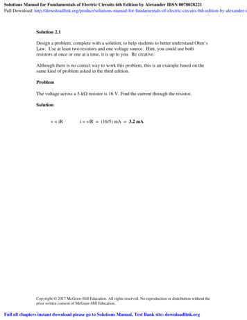
Example: r1 r2 r3 We need: RegistersAdder function (combinational logic)Wires
Example: r1 r2 r3 We need: Registersadder function (combinational logic)WiresSelection function We won’t always want r2 and r3
Combinational Logic Functions with no stateOutput is a function of the inputs only – no history addsubtractmultiplycount-onesFSM next state functionAll computation is done in binary Primitive circuit values are on/off, Vdd/GND, current/nocurrent
Review: Binary Encoding of Numbers Unsigned numbers bn-12n-1 bn-22n-2 . . . b0202s complement encoding of signed numbers -bn-12n-1 bn-22n-2 . . . b020 Same adder works for both unsigned and signed numbers To negate a number, invert all bits and add 1 As slow as add in worst case
Binary Addition Simple addition algorithm works:0 1 1 0 61 1 0 1 -3---------
Binary Addition Simple addition algorithm works:11000 1 1 0 61 1 0 1 -3--------0 0 1 13 Note: we drop the carry out of the high-order bitEach bit computes the same simple functions Sum f(a, b, Cin)Cout f(a, b, Cin) Ripple carry adder
Ripple-Carry Adder Each bit computes the same simple functions Sum f(a, b, Cin)Cout f(a, b, Cin)If we can write the function as a Boolean equation, we cangenerate the circuit
Combinational Logic Design We can translate a Boolean function into logic gates AND, OR, INVERTe.g. Homework problem g0 r0g1 g1 * r0’g2 g2 * r0’ * r1’
Homework Problem Homework problem Gates grow linearlyKeep to 4 inputs
Homework Problem Homework problem “carry” chain of ORs“multi-level logic”linear delaycan we do better?Yes we can!Any ideas?
Combinational Logic Design Finding the Boolean function? (e.g. Sum, Carry) Most functions are not obvious“Case analysis” always works Enumerate all possible input casesDetermine value for each caseConvert to Boolean equation(Not reasonable for large functions – more later)
Case Analysis for Sum and Cout There are 3 inputs and thus 8 different possibilitiesa00001111b00110011Cin Cout Sum0 001 0 1 0 1 0 1
Case Analysis for Sum and Cout There are 3 inputs and thus 8 different possibilitiesa00001111 b00110011Cin Cout Sum0 001 010 011 100 011 100 101 11Also known as a 3-2 counter
Truth Table to Boolean Function Straightforward processa b ca b ca b ca b ca b ca b ca b ca b ca00001111b00110011c01010101 Cout Sum 00 01 01 10 01 10 10 11 Cout a b c a b c a b c a b c Sum a b c a b c a b c a b c
Canonical forms: Sum Of Products Truth table is the unique signature of a Boolean functionMany alternative expressions may have the same truth tableCanonical form standard form for a Boolean expressionSum-of-products form –a.k.a. disjunctive normal form or minterm 00000011100101110111F A'BC AB'C' AB'C ABC' ABCF' A'B'C' A'B'C A'BC'16
Incompletely specified functions Example: binary coded decimal increment by 1 A0000000011111111BCD digits encode the decimal digits 0 – 9 in the bit patterns0000 – 00XXXXXXZ1010101010XXXXXXoff-set of Won-set of Wdon't care (DC) set of Wthese inputs patterns shouldnever be encountered in practice– we "don't care" about associatedoutput values, and this can beexploited in minimization
Regular Two-Level Logic Basis is canonical formNote notation for high-fanin gatesmintermsAND plane18OR plane
This is a “Canonical” Description Exactly one truth table for a function This equation is in general not minimal Canonical “Sum of Products” equatione.g. Cout a b c a b c a b c a b cMinimal equation: Much cheaper: Cout a b b c a c4 3-input ANDs 1 4-input ORvs. 3 2-input ANDs 1 3-input ORWhat about Sum?
Sum Sum a b c a b c a b c a b cCan we reduce this?Karnaugh map allows us to visualize the function Adjacencies allow minimizationCarrySumCAAB00010111C0101010101B 10AAB0001111000100111BSum cannot be minimized (with 2-level logic)
Cheaper Sum – Multi-level Circuit 12 gate inputs vs. 16 (ignore inverters)Slower (but smaller gates)
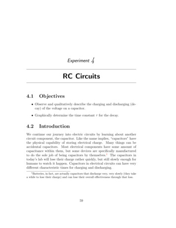
Multiplexers/selectorsMultiplexers/selectors: general concept 2n data inputs, n control inputs (called "selects"), 1 outputused to connect one of 2n inputs to the single outputcontrol signal pattern forms binary index of input connected to outpute.g. 2-1 muxS01Z S' I0 S I1I0I12:1muxZfunctional formSI0I12201logical formZSZI0I1two alternative formsfor a 2:1 Mux truth table
Multiplexers/selectorsMultiplexers/selectors: general concept 2n data inputs, n control inputs (called "selects"), 1 outputused to connect one of 2n inputs to the single outputcontrol signal pattern forms binary index of input connected to outpute.g. 2-1 muxS01Z S' I0 S I1I0I12:1muxZfunctional formSI0I12301logical formZSZI0I1two alternative formsfor a 2:1 Mux truth tableI100001111I000110011S01010101Z00100111
Gate level implementation of muxes 2:1 mux 4:1 mux24
Multiplexers/selectors (cont'd)I0I12:1muxSZI0I1I2I34:1muxS1 S0ZI0I1I2I3I4I5I6I78:1muxS2 S1 S025Z
Cascading multiplexers Large multiplexers can be implemented by cascadingsmaller ones using a tree 4:1mux2:1mux4:1muxS2 muxS28:1mux4:1muxS1 S0Z
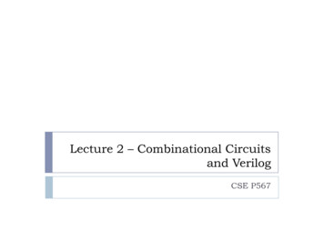
Decoders General idea: Convert a binary number into a “1-hot” number n inputs (address)2n outputsenable input (optional) 0 - all outputs 0EnableG0123:8 DEC 34567S2 S1 S0A27BA'B'C'A'B'CA'BC'A'BCAB'C'AB'CABC'ABCC
Gate level implementation of decoders 1:2 decoderGO0SO1 2:4 decoderGO0O1O2O3S1 S028
Cascading decoders Use a tree structure cheaper than 2-level implementation5:32 decoder 1x2:4 decoder4x3:8 decodersF2:4 DECS1 S0AB01230123:8 DEC 34567S2 S1 S00123:8 DEC 34567S2 S1 S0C29DEA'B'C'D'E'ABCDE0123:8 DEC 34567S2 S1 S00123:8 DEC 34567S2 S1 S0CDEA'BC'DE'AB'C'D'E'AB'CDE
2-Level Logic Minimization Important because of 2-level implementations By-hand methods – Karnaugh maps Only for small functionsGood for visualizationExact methods good up to 15 or so inputs PLAs – 1950sPALs – 1970s1950’s – Quine-McCluskey algorithmHeuristic methods for more than that 1970’s – Espresso
Multi-Level Logic Minimization Factor function into smaller functions Needed for FPGAs and semi-custom ASICs Smaller gatesFewer gatesDeeper circuit – cost/performance tradeoffCircuit libraries with “small” gatesDeveloped in the 1980s and 90sMuch more difficult problem than 2-level minimization Many different factoring methods
Simple Factoring - Decomposition Shannon/Ashenhurst Decomposition F(a, b, c, d, ) a’ Fa 0(b, c, d, ) a Fa 1(b, c, d, ) 2-1 Mux
Example f(a,b,c,d,e) ad' bde a'de' bd'c'
Logic Synthesis Compiles HDL into gates1. Elaboration – parse HDL program into standard form2. Logic optimization – minimize cost/maximizeperformance3. Tech mapping – map optimized circuit to availablelibrary components May require “re-synthesis”4. Physical Re-Synthesis – transform circuit when placingand routing Process is unpredictable
Logic Synthesis Insulates us from the details But we need to understand the implications of what wewrite in HDL Like a C or Java compilerJust like in C or JavaEach FPGA company has its own synthesis toolAnd Cadence, Synopsis, Mentor,
Verilog Introduction Two ways to describe: Behavioral Verilog describe what a component does, not how it does itsynthesized into a circuit that has this behaviorStructural Verilog list of components and how they are connectedjust like schematics, but using texthard to write, hard to decodeused to compose systems hierarchically from components
Verilog by Example Ripple-Carry Adder We will describe the full-adder as a behavioral moduleWe will connect these together in a higher-levelcomponent
full adder modulemodule full adder(input a,input b,input c,output sum,output carry);assign sum a & b & c a & b & c a & b & c a & b & c;assign carry a & b a & c b & c;endmodule
assign statement A single assignment equation One logical function (possibly multiple-bit value)Each assignment is a process Runs in parallel with all other processes Order of assignments does not matter!Executes whenever an input changes Just like logic gates
Verilog Operators
Alternative full adder modulemodule full adder(input a,input b,input c,output sum,output carry);assign { carry, sum } a b c;endmodule We add the 3 input bits together (count)The 2-bit result is assigned to the 2-bit bus { carry, sum }
adder4 modulemodule adder4(input [3:0] a,input [3:0] b,output [3:0] sum);wire carry0, carry1, carry2;full adder fa0(.a(a[0]), .b(b[0]), .c(0).sum(sum[0], .carry(carry0));full adder fa1(.a(a[1]), .b(b[1]), .c(carry0).sum(sum[1], .carry(carry1));full adder fa2(.a(a[2]), .b(b[2]), .c(carry1).sum(sum[2], .carry(carry2));full adder fa3(.a(a[3]), .b(b[3]), .c(carry2).sum(sum[3], .carry( ));endmodule This module just wires together the full-adders Connects the processes together
Verilog Data Types and Values Bits - value on a single wire 0, 1X - don’t careZ - undriven, tri-stateVectors of bits – busses A[3:0] - vector of 4 bits: A[3], A[2], A[1], A[0]Treated as an unsigned integer value by default e.g. A 0 ?Can declare variables ad signedConcatenating bits/vectors into a vector e.g. sign extendB[7:0] {A[3], A[3], A[3], A[3], A[3:0]};B[7:0] {4{A[3]}, A[3:0]};
Verilog Numbers 14 - ordinary decimal number-14 - 2’s complement representation12’b0000 0100 0110 - binary number with 12 bits( is ignored)3’h046 - hexadecimal number with 12 bitsVerilog values are unsigned by default e.g. C[4:0] A[3:0] B[3:0];if A 0110 (6) and B 1010(-6)C 10000 not 00000i.e. B is zero-padded, not sign-extendedFor maximum safety, declare length of all intermediates
always block Contains a small program that is executed whenever aninput changes A parallel process, just like an assign statementThe block can make multiple assignmentsThe program is executed sequentiallyThe program describes the function computed by the blockProgram is interpreted at compile time to generate a circuitCombinational – takes no time Even though the program semantics are sequential
Combinational always block always @(list of variables) block executes when any of the variables changeeasy to forget a variablewe will not use this stylealways @(*) This means to execute the program if any input changesJust like an assign
Alternative full adder modulemodule full adder(input a,input b,input c,output reg sum,output reg carry);always @(*) beginsum a & b & c a & b & c a & b & c a & b & c;carry a & b a & c b & c;endendmodule Order in the always block does matterVariables assigned in an always block must be declared as reg
Verilog Variables wire variable used to connect components togetherinputs and outputs are wires by default reg Any variable that is assigned in an always block outputs be declared as regscannot be assigned by an assign statementusually corresponds to a wire in the circuitis NOT a register in the circuitImportant: The names wire and reg do not mean anything!
Verilog if Same as C if statement// Simple 4-1 muxmodule mux4 (sel, A, B, C, D, Y);(input [1:0] sel, // 2-bit control signalinput A, input B, input C, input D,output reg Y);always @(*) beginif(sel else if (sel else if (sel else if (sel endendmodule2’b00)2’b01)2’b10)2’b11)YYYY A;B;C;D;
Verilog if Another way// Simple 4-1 muxmodule mux4 (sel, A, B, C, D, Y);(input [1:0] sel, // 2-bit control signalinput A, input B, input C, input D,output reg Y);always @(*) beginif (sel[0] 0)if (sel[1] 0)elseelseif (sel[1] 0)elseendendmoduleY A;Y B;Y C;Y D;
Verilog case Sequential execution of cases only first case that matches is executed (no break)default case can be used// Simple 4-1 muxmodule mux4 (sel, A, B, C, D, Y);(input [1:0] sel,// 2-bit control signalinput A, input B, input C, input D,output reg Y);always @(*) begincase (sel)2’b00: Y A;2’b01: Y B;2’b10: Y C;2’b11: Y D;endcaseendendmodule
Verilog case Without the default case, this would *not* be combinational! Assigning X to a variable means synthesis is free to assign any value// Simple binary encoder (input is 1-hot)module encode(input [7:0] A,// 8-bit input vectoroutput reg [2:0] Y); // 3-bit encoded outputalways @(*)case (A)8’b00000001: Y 0;8’b00000010: Y 1;8’b00000100: Y 2;8’b00001000: Y 3;8’b00010000: Y 4;8’b00100000: Y 5;8’b01000000: Y 6;8’b10000000: Y 7;default: Y 3’bX; // Don’t care when input is not 1-hotendcaseendmodule
Verilog for for is similar to Cfor statement is executed at compile time result is all that matters, not how result is calculated// simple encodermodule encode(input [7:0] A,// 8-bit input vectoroutput reg [2:0] Y); // 3-bit encoded outputinteger i;// Temporary variables for program onlyreg [7:0] test;always @(*) begintest 8b’00000001;Y 3’bX;for (i 0; i 8; i i 1) beginif (A test) Y i;test test 1;endendendmodule
Another Behavioral Example Combinational block that computes Conway’s Game of Life rulemodule life(inputinput [7:0]output s @(*) begincount 0;for (i 0; i 8; i i 1) count count neighbors[i];out 0;out out (count 3);out out ((self 1) & (count 2));endendmodule
Summary: Verilog for Combinational Logic Two alternatives: Each assign and always block compiles into a component Combinational function with some inputs and outputsAll components operate in parallel, continuously assign statement – simple logic equationalways block – allows complex program to describe
Canonical forms: Sum Of Products Truth table is the unique signature of a Boolean function Many alternative expressions may have the same truth table Canonical form standard form for a Boolean expression Sum-of-products form – a.k.a. disjunctive normal form or minterm expansion