Transcription
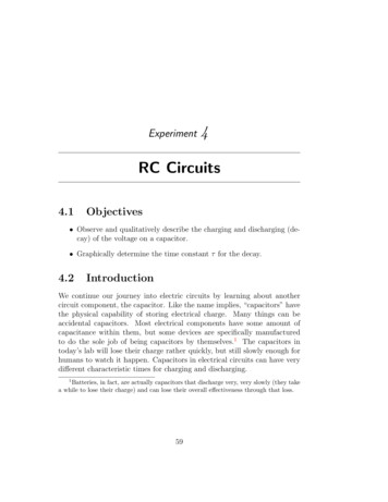
Experiment4RC Circuits4.1Objectives Observe and qualitatively describe the charging and discharging (decay) of the voltage on a capacitor. Graphically determine the time constant for the decay.4.2IntroductionWe continue our journey into electric circuits by learning about anothercircuit component, the capacitor. Like the name implies, “capacitors” havethe physical capability of storing electrical charge. Many things can beaccidental capacitors. Most electrical components have some amount ofcapacitance within them, but some devices are specifically manufacturedto do the sole job of being capacitors by themselves.1 The capacitors intoday’s lab will lose their charge rather quickly, but still slowly enough forhumans to watch it happen. Capacitors in electrical circuits can have verydi erent characteristic times for charging and discharging.1Batteries, in fact, are actually capacitors that discharge very, very slowly (they takea while to lose their charge) and can lose their overall e ectiveness through that loss.59
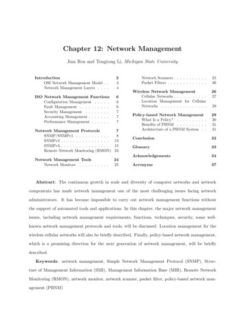
4. RC Circuits4.3Key ConceptsAs always, you can find a summary online at HyperPhysics2 . Look forkeywords: electricity and magnetism (capacitor, charging of a capacitor)To play with building circuits with capacitors, or to get a head starton trying out the circuits for today, run the computer simulation at struction-kit-ac.4.4TheoryThe CapacitorA capacitor is a device that stores electrical charge. The simplest kind is a“parallel-plate” capacitor: two flat metal plates placed nearly parallel andseparated by an insulating material such as dry air, plastic or ceramic. Sucha device is shown schematically in Fig. 4.1.Here is a description of how a capacitor stores electrical energy. Ifwe connect the two plates to a battery in a circuit, as shown in Fig. 4.1,the battery will drive charges around the circuit as an electric current.When the charges reach the plates they can’t go any further because of theinsulating gap so they collect on the plates, one plate becoming positivelycharged and the other negatively charged. This slow buildup of electriccharge actually begins to resist the addition of more charge as a /hph.htmlFigure 4.1: Schematic of a capacitor in a circuit with a battery.60Last updated February 5, 2014
4.4. Theorybegins to build across the plates, thus opposing the action of the battery.As a consequence, the current flowing in the circuit gets less and less (i.e. itdecays), falling to zero when the “back-voltage” on the capacitor is exactlyequal and opposite to the battery voltage.If we were to quickly disconnect the battery without touching the plates,the charge would remain on the plates. You could literally walk around withthis “stored” charge. Because the two plates have di erent signs of electriccharge, there is a net electric field between the two plates. Hence, thereis a voltage di erence across the plates. If, some time later, we connectthe plates again in a circuit, say this time with a light bulb in place ofthe battery, the plates will discharge through the bulb: the electrons onthe negatively charged plate will move around the circuit through the bulbto the positive plate until all the charges are equalized. During this shortdischarge period a current flows and the bulb will light up. The capacitorstored electrical energy from its original charging by the battery and thendischarged it through the light bulb. The speed with which the dischargeprocess (and conversely the charging process) can take place is limited bythe resistance R of the circuit connecting the plates and by the capacitanceC of the capacitor (a measure of its ability to hold charge).RC CircuitAn RC circuit is a circuit with a resistor and a capacitor in series connectedto a voltage source such as a battery.As with circuits made up only of resistors, electrical current can flow inthis RC circuit with one modification. A battery connected in series witha resistor will produce a constant current. The same battery in series witha capacitor will produce a time-varying current, which decays gradually tozero as the capacitor charges up. If the battery is removed and the circuitreconnected without the battery, a current will flow (for a short time) inthe opposite direction as the capacitor “discharges.” A measure of howlong these transient currents last in a given circuit is given by the timeconstant .The time it takes for these transient currents to decay depends on theresistance (R) and capacitance (C). The resistor resists the flow of current;it thus slows down the decay. The capacitance measures “capacity” tohold charge: like a bucket of water, a larger capacity container takes longerto empty than a smaller capacity container. Thus, the time constant ofLast updated February 5, 201461
4. RC Circuitsthe circuit gets larger for larger R and C. In detail, using the units ofcapacitance which are “farads”, (seconds) R(ohms) C(farads)(4.1)Isn’t it strange that ohms times farads equals seconds? Like many thingsin the physical world, it is just not intuitive. We can at least show thisby breaking the units down. From Ohm’s Law, R V /I. Current isthe amount of charge flowing per time, so I Q/t. Capacitance isproportional to how much charge can be stored per voltage applied, orC Q/V . So,RC R CVQ IVQ IQ Q/t tThe current does not fall to zero at time . Instead, is the time it takesfor the voltage of the discharging capacitor to drop to 37% of its originalvalue. It takes 5 to 6 s for the current to decay to essentially zero amps.Just as it takes time for the charged capacitor to discharge, it takes time tocharge the capacitor. Due to the unavoidable presence of resistance in thecircuit, the charge on the capacitor and its stored energy only approachesan essentially final (steady-state) value after a period of several times thetime constant of the circuit elements employed.62Last updated February 5, 2014
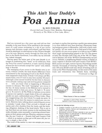
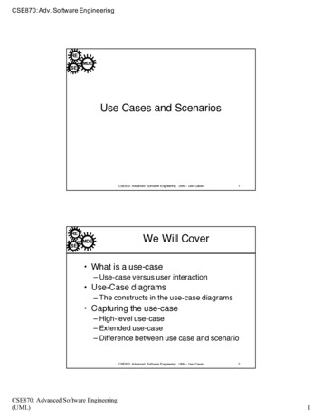
4.4. Theory(a) Charging(b) DischargingFigure 4.2: Schematics of charging and discharging a capacitor.Charging and discharging the RC circuitChargingInitially, a capacitor is in series with a resistor and disconnected from abattery so it is uncharged. If a switch is added to the circuit but is open,no current flows. Then, the switch is closed as in Fig. 4.2(a). Now thecapacitor will charge up and its voltage will increase. During this time, acurrent will flow producing a voltage across the resistor according to Ohm’sLaw, V IR. As the capacitor is charging up the current is actuallydecreasing due to the stored charge on the capacitor producing a voltagethat increasingly opposes the current. Since the current through the resistor(remember the resistor and capacitor are in series so the same current flowsthrough both) is decreasing then by Ohm’s law so is the resistor’s voltage.Fig. 4.3 graphs the behavior of the voltage across the capacitor and resistoras a function of the time constant, , of the circuit for a charging capacitor.Notice that as the capacitor is charging, the voltage across the capacitorincreases but the voltage across the resistor decreases.While the capacitor is charging, the voltages across the capacitor, VC ,and resistor, VR , can be expressed as VC (t) V0 1e t (4.2)VR (t) V0 e t(4.3)where e is the base of the natural logarithm and V0 is the initial voltage.The value of e is approximately 2.718. Remember that the time constant of a circuit depends on capacitance and resistance as RC. When thetime t is exactly equal to 1 time constant then t and the previousequations becomeLast updated February 5, 201463
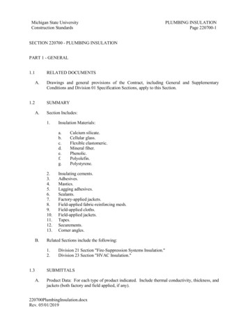
4. RC CircuitsVC V0 1 e 0.63V01(4.4)VR V0 e 1 0.37V0(4.5)This means that after t seconds, the capacitor has been chargedto 63% of its final value and the voltage across the resistor has dropped to37% of its peak (initial) value. After a very long time, the voltage acrossthe capacitor will essentially be equal to the battery’s voltage, V0 , and thevoltage across the resistor will be (for all practical purposes) zero.(a) Voltage across the capacitorVC .(b) Voltage across the resistor VR .Figure 4.3: Voltage in RC circuit components as a function of time for acharging capacitor where the time constant RC.DischargingIf we flip the switch to the position shown in Fig. 4.2(b), so that the batteryis no longer included in the circuit, we will discharge the capacitor. Nowthe charge stored on the capacitor is free to leave the plates and will causea current to flow. The current will be the largest at the beginning, t 0,and will decay away as charge leaves the capacitor’s plates. Since the current is decreasing the voltage di erence across the resistor is also decreasing(Ohm’s law again). Fig. 4.4 graphs the behavior of the voltage across thecapacitor and resistor as a function of the time constant, , of the circuitfor a discharging capacitor. For the case when the capacitor is dischargingnotice that both the voltage across the capacitor and the resistor are decaying to zero. It is critical to remember that the total voltage between thecapacitor and the resistor must add up to the applied voltage (Kirchho ’sloop law). When the circuit is disconnected from the power supply, then64Last updated February 5, 2014
4.4. Theory(a) Voltage across the capacitor VC .(b) Voltage across the resistor VR .Figure 4.4: Voltage in RC circuit components as a function of time for adischarging capacitor where the time constant RC.the sum of the voltages must be zero so the graph of the voltage across theresistor must be increasing from V0 to zero.For the case when the capacitor is discharging, the voltages across thecapacitor, VC , and resistor, VR , are given byVC V0 e t(4.6)VR V0 e t(4.7)Compare these equations to the ones given for when the capacitor ischarging and make sure you understand the di erences.It is usually easier to interpret a graph when the plot gives a straightline. For this lab we want to plot our voltages versus time, however, allof our equations for VC and VR involve exponentials. In order to get astraight line on our graphs we will use the logarithm function to find anequation that looks like a straight line. First, we divide the voltage acrossthe capacitor, VC , by the initial voltage, V0 , givingtVC e V0(4.8)Then we calculate the natural logarithm33The natural logarithm of x, ln(x), asks the question, “e raised to what power equalsx?” For example, to find ln e2 , we ask, “e raised to what power equals e2 ?” e raisedto the power 2 equals e2 , so ln e2 2. We can thus use the natural logarithm to getjust the power of e in an equation.Last updated February 5, 201465
4. RC Circuitsof both sides, yielding t VCln ln e V0 VCtln V0 (4.9)This last equation is a straight line, even though it may not look likeone at first glance. If y mx b is the equation of our straight line, then:1) time t is the independent variable x, 2) the term with the voltage VCthat changes with time is the dependent variable y, and 3) the slope m iseverything that is multiplied by the independent variable t. In this case,there is no term added to the t term, so the y-intercept b is zero. (You’llneed this for Question 1).Here is a more visual comparison between the equation for a straightline and Eq. 4.9 which is described in words above.ln y mx b VCt 0V0 Matching up variables we see thaty ln VCV0 x tm 1 b 0Repeated charging and dischargingIf we now repeat the charging and discharging process by alternating theswitch position every 6 seconds, the voltages will look like Fig. 4.5. Noticethat the voltage across the capacitor does not immediately match the voltage at the power supply, but rather it has some delay to get there. On the66Last updated February 5, 2014
4.4. Theoryother hand, the voltage across the resistor changes very quickly to matchthe power supply voltage, but then dies down over time (as the capacitorgains charge and slows the current down).Last updated February 5, 201467
4. RC Circuits(a) Alternating voltage on and o at the power supply.(b) Voltage across the capacitor.(c) Voltage across the resistor.Figure 4.5: Voltage during repeated cycles of charging and discharging for(top to bottom) the battery (which is constant at V0 or o ), the capacitor,and the resistor.68Last updated February 5, 2014
4.5. In today’s lab4.5In today’s labIn this particular experiment, we are hooking up a signal (or wave) generatorto an RC circuit, which allows us to reverse the applied voltage. In e ect,it will allow us to drive the circuit with alternating V0 and V0 as inputvoltage like in Fig. 4.6. The voltages as a function of time for the resistor andcapacitor are shown in Fig. 4.6. Then to see visually what is happening,we’ll install a two-color LED that changes color when the current goingthrough it changes directions.Last updated February 5, 201469
4. RC Circuits(a) Alternating direction of voltage from signal generator.(b) Voltage across the capacitor.(c) Voltage across the resistor.Figure 4.6: Voltages for repeated charging and discharging with a signalgenerator.70Last updated February 5, 2014
4.6. Equipment4.6Equipment Signal generator (see Figure 4.10) DC power supply Desktop timer (or a timer on the internet) Resistors and capacitors Two-color Light Emitting Diode (LED) (see Figure 4.11) Circuit breadboardSafety Tips When plugging or unplugging wires, first turn o all electronicsthat are connected or will become connected to the circuit. Todaythere is one instance where you will unplug first before turning o thepower supply. Be sure to not touch the ends of the wires while orafter you are unplugging them.4.7ProcedureMeasuring the time constantFirst we want to measure the time constant . This means we need tocharge the capacitor fully, then let it discharge through a resistor while wemeasure the voltage as it changes over
05.02.2014 · RC Circuit An RC circuit is a circuit with a resistor and a capacitor in series connected to a voltage source such as a battery. As with circuits made up only of