Transcription
Department of Electronics and Communication Engineering SVCETADC lab manualSri Venkateswara College of Engineering and Technology, Chittoor.(Autonomous)Department of Electronics and Communication EngineeringANALOG AND DIGITAL CIRCUITS LAB MANUAL(17AEC17)(II B.Tech-II Semester EEE)Name :Roll no. :Laboratory Name :1
Department of Electronics and Communication Engineering SVCETADC lab manual17AEC17 ANALOG AND DIGITAL CIRCUITS LABObjectives:The course will provide the student:1. Generation and processing of sinusoidal and non-sinusoidal signals.2. Analysis and design of various multivibrator circuits.3. Fundamentals of basic logic gates and its applications.4. To design a combinational and sequential logic circuits.Minimum Twelve experiments to be conducted (Six from each part A and part B):Analog Electronics LAB (PART-A):1. Linear wave shaping.2. Non Linear wave shaping – Clippers.3. Non Linear wave shaping – Clamper's.4. Transistor as a switch.5. Astable Multivibrator.6. Monostable Multivibrator.7.Bistable Multivibrator.8.Schmitt Trigger.Digital Electronics LAB (PART-B):1. Study of Logic Gates & Some applications.2. Half adder & Full adder.3. Half Subtractor and full subtractor4. 3-8 decoder-74X1385. 8-3 encoder-74X148.6. 8X1 multiplexer -74X1517. 2X4 de-multiplexer -74X1558. 4-bit comparator-74X85Outcomes:After completion of this course the student will be able to:1. Generate and process sinusoidal and non-sinusoidal signals.2. Design and analyze various multivibrator circuits.3. Understand fundamentals of basic logic gates and design applications.4. Skilled in the design of combinational and sequential circuits.2
Department of Electronics and Communication Engineering SVCETADC lab manualNAME:REG. NO. :INDEXS NoDateName of the ExperimentSignature3
Department of Electronics and Communication Engineering SVCETADC lab manualLIST OF EXPERIMENTCYCLE IAnalog Electronics LAB :1. Linear wave shaping.2. Non Linear wave shaping – Clippers.3. Non Linear wave shaping – Clamper's.4. Transistor as a switch.5. Astable Multivibrator.6.Schmitt Trigger.CYCLE IIDigital Electronics LAB:1. Study of Logic Gates & Some applications.2. 3-8 decoder-74X1383. 8-3 encoder-74X148.4. 8X1 multiplexer -74X1515. 2X4 de-multiplexer -74X1556. 4-bit comparator-74X854
Department of Electronics and Communication Engineering SVCETADC lab manualExp No:Date:LINEAR WAVE SHAPING(RC INTEGRATOR & RC DIFFERENTIATOR)AIM:i) To design and verify an integrator (Low pass RC) circuit.ii) To design and verify a differentiator (High pass RC) circuit.COMPONENTS REQUIRED:1. Resistors1kΩ, 10kΩ, 100kΩ2. Capacitor0.1 μf (1No.)3. Bread Board4. Connecting wires5. CRO & Probes6. Function GeneratorTHEORY:The process in which non sinusoidal signal is altered by transmission through a linearnetwork is called “Linear wave shaping”.i)RC INTEGRATOR (or) LOW PASS FILTER: A Low pass circuit is a circuit which transmitsonly low frequency signals and alternates (or) stops high frequency signals at zero frequency, thereactance of the capacitor is infinity (i.e. the capacitor acts as a open circuit). So the entire inputappears at the output i.e. the input is transmitted to the output with zero alternation. So the entireoutput is same as the input i.e. the gain is unity. As the frequency increase the capacitor reactance𝑋𝐶 1/2п𝑓𝑐 decreases and so the output decreases. At high frequencies the capacitor virtuallyacts as a short circuit and the output falls to zero. RC Integrator can be operated in three differentmodes i.e. Large Time constant(𝑅𝐶 𝑇), Medium Time constant (𝑅𝐶 𝑇) & Short Timeconstant (𝑅𝐶 𝑇).ii)RC DIFFERENTIATOR (or) HIGH PASS FILTER: In a high pass RC circuit, at zerofrequency the reactance of the capacitor is infinity and so it blocks the input and hence the output iszero. Hence this capacitor is called the blocking capacitor and this circuit also called the capacitivecoupling circuit, is used to provide DC isolation between the input and output. As the frequencyincreases the reactance of the capacitor decreases and hence the output and gain increases. At veryhigh frequencies the capacitive reactance is very small so a very small voltage appears acrosscapacitor and so the output is almost equal to the input and the gain is equal to unity. Since thiscircuit attenuates low frequency signals and allows transmission of high frequency signals with5
Department of Electronics and Communication Engineering SVCETADC lab manuallittle or no attenuation, it is called a high pass circuit. RC differentiator can be operated in threedifferent modes i.e. Large Time constant(𝑅𝐶 𝑇), Medium Time constant (𝑅𝐶 𝑇) & ShortTime constant (𝑅𝐶 𝑇).CIRCUIT DIAGRAM:i) RC INTEGRATOR (or) LOW PASS FILTER:R 1kΩ, 10kΩ, 100kΩVi (From function generator)Vo( Output in CRO )C 0.1 μfii) RC DIFFERENTIATOR (or) HIGH PASS FILTER:C 0.1 μfVi (From function generator)Vo( Output in CRO )R 1kΩ, 10kΩ, 100kΩPROCEDURE:1. Connect the low pass circuit as per the circuit diagram.2. Connect the function generator at the input terminals and CRO at the output terminals.3. Apply a square wave signal of 10V amplitude and 1 KHz frequency at input.4. Observe the output waveform of the circuit for different time constants.Large Time constant(𝑅𝐶 𝑇), Medium Time constant(𝑅𝐶 𝑇),Short Time constant(𝑅𝐶 𝑇).5. Repeat the above procedure for high pass circuit also.6. Draw the graph for both low pass and high pass circuits for above three cases of time constants.6
Department of Electronics and Communication Engineering SVCETADC lab manualTABULATION :i)S.noTime constanti)S.noRC INTEGRATOR (or) LOW PASS FILTER:Amplitude (v)Time period (ms)RC DIFFERENTIATOR (or) HIGH PASS FILTER:Time constantAmplitude (v)Time period (ms)APPLICATIONS:1. Linear wave shaping networks as a low pass filter and high pass filter used to control thetransmission with respect to frequency.2. The output of High pass network for less time constant can be used as a trigger for monostablemultivibrator.3. The low pass network can be used to generate the triangular wave for high time constant.7
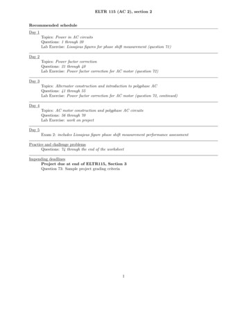
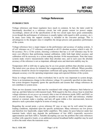
Department of Electronics and Communication Engineering SVCETADC lab manualMODEL GRAPH:i) RC INTEGRATOR (or) LOW PASS FILTER:VV i(Input square wave) 5VV o(Output) Large Time Constant (𝑹𝑪 𝑻)t (in m Sec)0- 5VVV i (Input square wave) 5VV o (Output) Medium Time Constant (𝑹𝑪 𝑻)0t (in m Sec)- 5VV 5VV i (Input square wave)V o (Output) Short Time Constant (𝑹𝑪 𝑻)t (in m Sec)0- 5V8
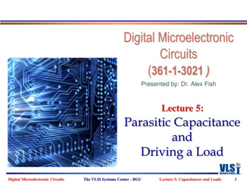
Department of Electronics and Communication Engineering SVCETii)ADC lab manualRC DIFFERENTIATOR (or) HIGH PASS FILTER:VV i (Input square wave) 5V0V o (Output) Short Time Constant (𝑹𝑪 𝑻)t (in m Sec)- 5VV 5V0V i (Input square wave)V o (Output) Medium Time Constant (𝑹𝑪 𝑻)t (in m Sec)- 5VV 5V0V i (Input square wave) V o (Output)Large Time Constant (𝑹𝑪 𝑻)t (in m Sec)- 5VRESULT:Hence the RC Integrator & RC Differentiator circuits were designed and outputwaveforms are verified.9
Department of Electronics and Communication Engineering SVCETADC lab manual10
Department of Electronics and Communication Engineering SVCETADC lab manualExp No:Date:NON LINEAR WAVE SHAPING – CLIPPERSAIM:To design and verify waveforms of different clipping circuits with different referencevoltage.COMPONENTS REQUIRED:1. Resistors 1kΩ (1No.)2. Diode 1N4007 (2No.)3. Bread Board4. Connecting wires5. CRO & Probes6. Function Generator7. Regulated Power Supply (0 - 30V)THEORY:The non-linear semiconductor diode in combination with resistor can function asclipper circuit. Energy storage components like capacitor etc. are not required in the basic process ofclipping. These circuits will select part of an arbitrary waveform which lies above or belowsome particular reference voltage level and that selected part of the waveform is used fortransmission. So they are referred as voltage limiters, current limiters, amplitude selectors or slicers.There are three different types of clipping circuits.1) Positive Clipping circuit.2) Negative Clipping.3) Positive and Negative Clipping (slicer).In positive clipping circuit positive cycle of Sinusoidal signal is clipped and negativePortion of sinusoidal signal is obtained in the output. If reference voltage is added, instead ofcomplete positive cycle that portion of the positive cycle which is above the reference voltage valueis clipped. In negative clipping circuit instead of positive portion of sinusoidal signal, negativePortion is clipped. In slicer both positive and negative portions of the sinusoidal signal are clipped.Operation can be explained based on equations as shown below:1. When Vi VR Vγ, Diode is reverse biased (OFF). Output follows the input.2. When Vi VR Vγ, Diode is forward biased (ON). And the Output is equal to (VR Vγ).Here Vi is Supplied input voltage, VR is connected reference voltage, Vγ is diode cut-in voltage11
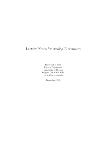
Department of Electronics and Communication Engineering SVCETADC lab manualAPPLICATIONS:1. Used in radars, digital computers and other electronic systems for removing unwanted portions ofthe input signal voltages above or below a specified level.2. used in radio-receivers for communication circuits where noise pulses that rise well above thesignal amplitude are clipped down to the desired level.CIRCUIT DIAGRAMSMODEL GRAPHSInput WaveformsOutput waveforms1) Positive clipper:2) Positive clipper with positive reference voltage:3) Positive clipper with negative reference voltage:12
Department of Electronics and Communication Engineering SVCETADC lab manual4) Negative clipper:5) Negative clipper with negative reference voltage:6) Negative clipper with positive reference:7) Slicer (Two level clippers):13
Department of Electronics and Communication Engineering SVCETADC lab manualTabular column:PROCEDURE:1. Connect the circuit elements as shown in the Circuit Diagram.2. A Sinusoidal voltage of 10V and frequency of 1kHz is appliedto the circuit as an input.3. Note down the corresponding output wave forms from C.R.O andEnter the values in table.4. Plot the graph from above readings.14
Department of Electronics and Communication Engineering SVCETADC lab manualRESULT:Hence different clipping circuits were designed and corresponding outputs were verified.15
Department of Electronics and Communication Engineering SVCETADC lab manual16
Department of Electronics and Communication Engineering SVCETADC lab manualExp No:Date:NON LINEAR WAVE SHAPING – CLAMPERSAIM:To design and verify the characteristics of different clamping circuits with different referencevoltage.COMPONENTS REQUIRED:1. Capacitor 10 μ F (1 No)2. Diode IN4007 (1 No)3. Bread Board4. Connecting wires5. CRO & Probes6. Function GeneratorTHEORY:“A clamping circuit is one that takes an input waveform and provides an output that isa faithful replica of its shape but has one edge tightly clamped to the zero voltagereference point”.There are various types of Clamping circuits, which are mentioned below:1. Positive Clamping Circuit.2. Negative Clamping Circuit.3. Positive Clamping with positive reference voltage.4. Negative Clamping with positive reference voltage.5. Positive Clamping with negative reference voltage.6. Negative Clamping with negative reference voltage.17
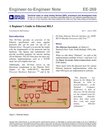
Department of Electronics and Communication Engineering SVCETCIRCUIT DIAGRAM:ADC lab manualMODEL GRAPH:INPUT WAVEFORMOUTPUT WAVEFORM1. Positive Clamping Circuit:2. Positive Clamping with negetive reference voltage:3. Positive Clamping with Positive reference voltage:18
Department of Electronics and Communication Engineering SVCETADC lab manual4. Negative Clamping Circuit:5. Negative Clamping with positive reference voltage:6. Negative Clamping with negative reference voltage:19
Department of Electronics and Communication Engineering SVCETADC lab manualPROCEDURE:1. Connect the circuit elements as shown in the Circuit Diagram.2. A Sinusoidal voltage of 10V and frequency of 1kHz Hz is appliedto the circuit as an input.3. Note down the corresponding output wave forms in C.R.O andplot the graph.TABULATIONS.noType of clampingReference voltageAmplitude (v)Time period (ms)APPLICATIONS:1. Used in T.V receivers as dc restorers.2. Used in test equipment, radar systems, electronic countermeasure systems, and sonarsystems20
Department of Electronics and Communication Engineering SVCETADC lab manualRESULT:Hence different clamping circuits were designed and outputs were verified.21
Department of Electronics and Communication Engineering SVCETADC lab manual22
Department of Electronics and Communication Engineering SVCETADC lab manualExp No:Date:TRANSISTOR AS A SWITCHAIM:To construct and verify the switching characteristics of the transistor.COMPONENTS REQUIRED:1. Transistor BC 547 ---------- 1No2. Capacitor 10 μ F ------------1No3. Resistors 100Ω, 1K Ω, 2.2KK Ω ---- 1No each4. Bread Board5. Connecting wires as required6. CRO & Probes7. Function Generator8. Regulated Power Supply (0 - 30V)THEORY:The operation of a transistor as a switch can be illustrated using circuit diagram. When theinput voltage is negative or zero, then is in cut off and so no current flows through RC. Hence theoutput voltage is equal to Vcc. When its voltage jumps to the voltage “V”, the transistor will bedrawn into saturation.Thus the transistor can turn off depending upon whether input voltage is positive or negative.Thus the transistor can acts as a switch. When no signal is applied the transistor will be held insaturation by the connection of base to supply voltage through the resistor.23
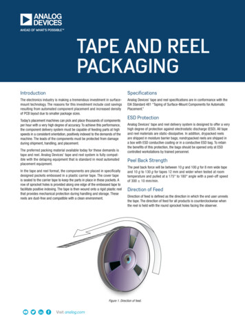
Department of Electronics and Communication Engineering SVCETADC lab manualCIRCUIT DIAGRAM: VccR2 2.2KΏR3 1KΏC 10μ FCR1 100 Ω Q BC547BViInputfrom FGMODEL GRAPH:VoOutput(In CRO)ETRANSISTOR PIN DETAILS:V 5VInputWaveform 0BC547t-5VC B E 10V VOutputwaveform0t24
Department of Electronics and Communication Engineering SVCETADC lab manualPROCEDURE:1. Connect the circuit elements as shown in the Circuit
Department of Electronics and Communication Engineering SVCET ADC lab manual 2 17AEC17 ANALOG AND DIGITAL CIRCUITS LAB Objectives: The course will provide the student: 1. Generation and processing of sinusoidal and non-sinusoidal signals. 2.