Transcription
11/6/2014Code Requirements for Nuclear Safety-Related ConcreteStructures (ACI 349)Session 1 – Introduction, Materials, and RequirementsThis Webinar is sponsored by ACI. The ideas expressed, however, are thoseof the speakers and do not necessarily reflect the views of ACI or itscommittees. The audience is expected to exercise judgment as to theappropriate application of the information.Please adjust your audio level at this time.WEBINAR For continuing education credit, attendees must purchase the ACI webinartitled “Nuclear Safety-Related Concrete Structures” for 200 ACImembers/ 250 nonmembers. Attendees that log in with full name andemail address, and attend the entire webinar, will receive certificates foreach part of the four-part webinar series. Totaling 5 ProfessionalDevelopment Hours (PDH) of continuing education credit. Visitwww.ACIeLearning.org and login to access the ACI eLearning site. For site license purchasers, if you view the webinar within a group, yourname, email address and signature must appear on your organization’sgroup attendance sign-in sheet. Corporate group discounts are available for those attending the livewebinar by contacting Claire Hiltz at Claire.Hiltz@concrete.org. Questions related to specific materials, methods, and services will beaddressed at the conclusion of this presentation.WEBINAR1
11/6/2014American Concrete Institute is a Registered Provider with The AmericanInstitute of Architects Continuing Education Systems (AIA/CES).Credit(s) earned on completion of this eLearning course will be reported toAIA/CES for AIA members.The eLearning course based on this webinar is registered with AIA/CES forcontinuing professional education. As such, it does not include content thatmay be deemed or construed to be an approval or endorsement by the AIAof any material of construction or any method or manner of handling, using,distributing, or dealing in any material or product. The American Institute of Architects has approved this course for1 AIA/CES LU/HSW Learning Unit.The American Institute of Architects has approvedthis course for 1 AIA/CES LU/HSW learning unit.ACI is an AIA/CES registered provider.WEBINARCode Requirements for Nuclear Safety-Related ConcreteStructures (ACI 349)Session 1 – Introduction, Materials, and RequirementsLearning Objectives: Recognize the scope of structures covered by ACI 349.Identify the difference between ACI 318-08 and ACI 349-13.Identify the material requirements for design in accordance with ACI 349.Understand the basic assumptions and design philosophy behindreinforced concrete design according to ACI 349. Identify design and detailing requirements that are specific to nuclearconstruction. Become acquainted with ACI Committee 349 documents:1) 349.1R-07, Reinforced Concrete Design for Thermal Effects onNuclear Power Plant Structures;2) 349.2R-07, Guide to the Concrete Capacity Design (CCD) Method—Embedment Design Examples; and3) 349.3R-02, Evaluation of Existing Nuclear Safety-Related ConcreteStructures.WEBINAR2
11/6/2014Partha S. GhosalPartha S. Ghosal, P.E. is a Senior Program Manager at Tennessee ValleyAuthority (TVA) in Chattanooga TN. He has over 35 years of experience inthe design, inspection and evaluation of nuclear power plant structures. Hehas served on expert panels and peer reviewed many projects. He isMember of the American Concrete Institute (ACI), Member of the AmericanSociety of Civil Engineers (ASCE), Member of the American Society ofMechanical Engineers (ASME) and Member of the Structural EngineeringInstitute (SEI). He is also a licensed professional engineer (PE) inWisconsin. He is a member of ACI 349, ACI 355 and ASME Section III, Div 2.Committees for concrete nuclear structures.WEBINARHerman L. GravesHerman L. Graves, III, P.E., FACI is a consulting engineer. He worked as aSenior Structural Engineer at the U.S. Nuclear Regulatory Commission(NRC) from 1980 to 2013, where he formulated and managed researchprograms related to nuclear civil/structural engineering.Mr. Graves has been an ACI member for more than 30 years. He is theimmediate past chairman of ACI Committee 349, “Concrete NuclearStructures,” a member of ACI Committee 355, “Anchorage to Concrete,” anda member of the Committee on Awards for Papers. He was named a Fellowof ACI in 2008, and has contributed to various ACI publications as an authorand technical reviewer.He is a licensed Professional Engineer inWashington, DC and Maryland.WEBINAR3
11/6/2014CODE REQUIREMENTS FOR NUCLEARSAFTEY RELATED CONCRETESTRUCTURESSession 1By Javeed Munshi, PhD., P.E., F. ACI, F. ASCEPartha Ghosal, M.S., P.E.Herman L. Graves, III, M.S.,P.E., F. ACIWEBINAR2ACI Standards Developing Process Industry need/volunteer interest Technical committee formation/expansion Document drafting Balloting/resolution of negatives Internal quality (TAC) Public Review/address comments Standards Board (appeals) AdoptionWEBINAR1
11/6/20143ACI HISTORICAL BACKGROUND American Concrete Institute was formed in 1904First Building Code with “ACI 318” published in 1941First ACI 349 adopted in 1976, based on ACI 318-71First appearance of Chapter 21 in ACI 318-77 as“Special Provisions for Seismic Design” Chapter 21 added to ACI 349-97 ACI 349-06 supersedes ACI 349-01, adoptedNovember 7, 2006, and published September 2007.The format of this Code is based on the ACI 318-05. ACI 349-13 Supersedes ACI 349-06, adopted August2013, and published June 2014.WEBINAR4ACI HISTORICAL BACKGROUND-cont.ACI has two committees specifically related tonuclear design and construction: ACI 349 (ConcreteNuclear Structures) and ACI 359 (ConcreteComponents for Nuclear Reactors). ACI 349 hasdeveloped “Code Requirements for Nuclear SafetyRelated Concrete Structures (ACI 349-13) andCommentary.” ACI 359 is a joint committee betweenACI and ASME.WEBINAR2
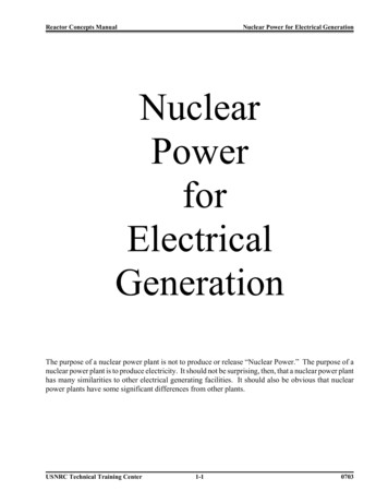
11/6/20145Preview Recognize the scope of structures covered by ACI349 Identify the material requirements for design inaccordance with ACI 349 Basic assumptions and design philosophyaccording to ACI 349 Detailing requirements for reinforced concrete,including seismic requirements. Identify design and detailing requirements that arespecific to nuclear constructionWEBINAR6SOURCE: USNRC Backgrounder publication. Office of Public Affairs, 6/2008.WEBINAR3
11/6/20147Code Requirements for Nuclear SafetyRelated Concrete Structures (ACI 349-13)Chapter 1—General RequirementsChapter 2—DefinitionsChapter 3—MaterialsChapter 4—Durability RequirementsChapter 5—Concrete Quality, Mixing, and PlacingChapter 6—Formwork, Embedded Pipes, and ConstructionJointsChapter 7—Details of ReinforcementChapter 8—Analysis and DesignChapter 9—Strength and Serviceability RequirementsWEBINAR8ACI 349-13, cont.Chapter 10—Flexure and Axial LoadsChapter 11—Shear and TorsionChapter 12—Development and Splices of ReinforcementChapter 13—Two-Way Slab SystemsChapter 14—WallsChapter 15—FootingsChapter 16—Precast ConcreteChapter 17—Composite Concrete Flexural MembersChapter 18—Prestressed ConcreteChapter 19—ShellsChapter 20—Strength Evaluation of Existing StructuresChapter 21—Special Provisions for Seismic DesignWEBINAR4
11/6/20149ACI 349-13, cont.Appendices APPENDIX A—Strut-And-Tie Models APPENDIX B— Blank APPENDIX C— Alternative Load andStrength-Reduction Factors APPENDIX D— Anchoring To Concrete APPENDIX E—Thermal Considerations APPENDIX F—Special Provisions forImpulsive and Impactive EffectsWEBINAR10ACI 349-13, cont.The format of this Code is based and depends on the ACI318-08 Code requirements and Commentary. This Codeshould be used in conjunction with ACI 318-08.The philosophy of ACI 349 is to assure general elasticseismic response whereas ACI 318 permits large inelasticdeformations. That is why Chapter 21 ‘Provisions forEarthquake-Resistant Design’.is a stand alone chapter in ACI349-13.WEBINAR5
11/6/201411Chapter 1—General RequirementsACI 318 is intended to be referenced by a generalbuilding code imposed by law in a state or locality.It is then administered and enforced by the localbuilding official. ACI 349 is intended for concretestructures where protection against potentialradioactive releases is a concern: as such thesestructures are regulated in the US by the USNuclear Regulatory Commission.WEBINAR12Chapter 2—Notation and DefinitionsSee code for changes, e.g. All notations and definitions in ACI 318-08 are the same as used in thisCode. Additional definitions relevant to ACI 349-13 only has been noted inthis chapter. Few unique definitions have been listed below. Anchor—A steel element either cast into concrete or post-installed into ahardened concrete member and used to transmit applied loads, including headedbolts, headed studs, expansion anchors, or specialty pretensioning, a deviceused to anchor the inserts; as used in Appendix D. Authority Having Jurisdiction (AHJ) — a federal government agency (oragencies), such as the U.S. Nuclear Regulatory Commission, the Department ofEnergy, that is empowered to enforce regulations affecting the design,construction, and operation of nuclear facilities. Elastic Analysis — an analysis of deformations and internal forces based on equilibrium,compatibility of strains, and assumed elastic behavior, and representing to a suitableapproximation the three-dimensional action of the shell together with its auxiliary members. Embedment— A steel component embedded in the concrete to transmit appliedloads to the concrete structure. The embedment can be fabricated of plates,shapes, fasteners, reinforcing bars, shear connectors, inserts, or any combinationthereof.WEBINAR6
11/6/201413Chapter 2—Notations andDefinitions, cont Massive concrete—Mass of concrete of sufficient dimensions toproduce excessive temperatures due to heat of hydration unlessspecial precautions are taken regarding concrete placementtemperatures, placing rate, or heat removal. Portions of the structureto be treated as massive concrete shall be so identified on the designdrawings or specifications. Operating basis earthquake—The operating basis earthquake(OBE) for a reactor site is that which produces the vibratory groundmotion for which those features of the nuclear plant necessary forcontinued operation without undue risk to the health and safety of thepublic are designed to remain functional.WEBINAR14Chapter 2—Notations andDefinitions, cont Regulatory Authority— A governmental agency that regulatesbusinesses in the public interest (such as U.S. Nuclear RegulatoryCommission - an independent federal agency created in 1974 to licenseand regulate nuclear power plants). Seismic Hook — A hook on a stirrup, hoop, or crosstie having a bendnot less than 135 degrees, except that circular hoops shall have a bendnot less than 90 degrees. Hooks shall have a 6db (but not less than 3 in)extension that engages the longitudinal reinforcement and projects intothe interior of the stirrup or hoop.WEBINAR7
11/6/201415Chapter 3—Materials ACI 349 has revised the limits of the yield strength ofreinforcement of 60,000 psi to 80,000 psi. ACI 349 excludes requirements for light weight concretesince concrete requirements are generally governed byradiation shielding considerations.WEBINAR16Chapter 3—Materials, cont. 3.1.3—Tests of materialsA complete record of tests of materials and of concrete shall beavailable for inspection as required by Section 1.3.2.3.3 Aggregates 3.3.1 Concrete aggregates shall conform to one of the followingspecifications:(a) Normalweight: ASTM C33;(b) Radiation-Shielding: (ASTM C637).Exception: Aggregates failing to meet ASTM C33 or C637, but thathave been shown by special test or actual service to produceconcrete of adequate strength and durability, shall be permitted tobe used for normal weight concrete where authorized by thelicensed design professional.WEBINAR8
11/6/201417Chapter 3—Materials, cont. Section 3.3.3.1- Tests for potential reactivity shall beperformed before usage in construction unless such tests arespecifically exempted by the design specifications as notbeing applicable. 3.5 – Steel Reinforcement3.5.3.1.1 A minimum of one tensile test shall be required foreach 50 tons of each bar size produced from each heat ofsteel (ASTM A370).WEBINAR18Chapter 3—Materials, cont. 3.6 — Admixtures 3.6.6.1 Tests for compliance with the specification for each admixture shallbe required before initial shipment and acceptance on site for usage inconstruction and periodically thereafter. 3.6.6.2 An infrared spectrum trace of the conformance test sample of airentraining and water-reducing admixture shall be furnished with theconformance test results (ASTM E204). 3.7—Storage and identification of materials3.7.1 Measures shall be established to provide for storage of all materials so as toprevent damage or deterioration. 3.7.4 Prestressing system materials shall be stored in such a manner as to insuretraceability to the Certified Material Test Report during production and while in transitand storage.WEBINAR9
11/6/201419Chapter 4—Durability requirements Chapter 4 in ACI 349-13 is the same as in ACI 318-08except that all references to lightweight concrete arenot applicable. Water-cementitious materials ratio described in Table4.3.1 The followings are described in Tables 4.2.1, 4.3.1 and4.4.1. Freezing and thawing exposures Sulfate exposures Corrosion protection of reinforcementWEBINAR20Chapter 5—Concrete Quality, Mixing &Placing R5.1.6— This Code does not include provisions for the useof fiber-reinforced concrete in nuclear facilities. 5.6.2—Frequency of testing 5.6.2.1 Specimens for strength tests of each class of concrete placed eachday shall be taken not less than once a day, nor less than once for each 100yd3 of concrete placed. When the standard deviation for 30 consecutivetests of a given class is less than 600 psi, the amount of concrete placedbetween tests is permitted to be increased by 50 yd3 for each 100 psi thestandard deviation is below 600 psi, except that the minimum testing rateshould not be less than one test for each production shift when concrete isplaced on more than one shift per day or not less than one test for each 200yd3 of concrete placed. 5.6.2.3 When total quantity of a given class of concrete is less than 50 yd3,strength tests are not required when evidence of satisfactory strength is submitted to and approved by the licensed design professional.WEBINAR10
11/6/2014Chapter 5—Concrete Quality, Mixing& Placing (Continued)215.9.3 Aluminum pipe shall not be used to convey concrete.5.10.4 Retempered concrete shall not be used.5.10.9 Where conditions make consolidation difficult, or wherereinforcement is congested, batches can be reproportioned to substitutethe larger of the coarse aggregate gradations with finer coarseaggregate or self-consolidating concrete may be used. Suchsubstitutions shall be limited to only those made in limited areas ofspecific difficulty and subject to the approval of the licensed designprofessional as to location, mix proportioning, or alterations of the mix.WEBINARChapter 5—Concrete Quality, Mixing& Placing (Continued)225.11 — Curing5.11.5 Where a liquid membrane curing compound is used, particularattention shall be given to its compatibility with any protectivecoatings that are to be applied following curing. 5.11.6 The method of curing shall be stated in the constructionspecification.5.13—Hot Weather Requirements5.13.2 The method of controlling concrete temperatures shall bespecified in the construction specification.er requirementsWEBINAR11
11/6/201423Chapter 6—Formwork, Embedments, andConstruction Joints 6.3.7.1 All piping and fittings except as provided in 6.3.7.1.1 shall be testedas a unit for leaks before concrete placement. Pressure tests shall be inaccordance with ASME B31.3 standard. Where pressure testing requirementsare not specified in ASME B31.3, pressure testing shall meet the followingrequirements: 1) the testing pressure above atmospheric pressure shall be 50percent in excess of pressure to which piping and fittings will be subjected,but minimum testing pressure shall not be less than 150 psi aboveatmospheric pressure; 2) the test pressure shall be held for four hours with nodrop in pressure allowed, except that which is caused by a drop in airtemperature. 6.3.7.1.1 Drain pipes and other piping designed for pressures of notmore than 1 psi above atmospheric pressure need not be tested asrequired in 6.3.7.1.6.3.7.1.2 Pipes carrying liquid, gas, or vapor that is explosive orinjurious to health shall again be tested as specified in 6.3.7.1 after theconcrete has reached its design strength.WEBINAR24Chapter 6—Formwork, Embedments, andConstruction Joints6.3.14 All piping containing liquid, gas, or vapor pressure in excess of 200 psi above atmosphericpressure or temperature in excess of 150 F shall be designed to limit concrete and reinforcementstresses to allowable design strength and to limit concrete temperatures to the following:a) For normal operation or any other long-term period, the temperatures shall not exceed 150 F,except for local areas which are allowed to have increased temperatures not to exceed 200 F.This limit is permitted to be increased to 180 F for general surface area and 230 F for local surfacearea if the tested concrete strength (for example, measured compressive strength at 28 days ormore) is equal to or greater than 115 percent of the specified 28-day compressive design strength.b) For accident or any other short-term period, the temperatures shall not exceed 350 F for theinterior surface. Local areas, however, are allowed to reach 650 F from fluid jets in the event of apipe failure.c) Higher temperatures than given in Items (a) and (b) are allowed in the concrete if tests areprovided to evaluate the reduction in strength and this reduction is applied to the design strength.Evidence shall also be provided that verifies that the increased temperatures do not causedeterioration of the concrete with or in the absence of applied loads.WEBINAR12
11/6/201425CHAPTER 7DETAILS OF REINFORCEMENTWEBINAR26Standard Hooks for Primary ReinforcementSection 7.1Standard hook is used to mean either 180-degree bend plus 4dbextension or 90-degree bend with 12 db extension at free end of barTable 7.2 – Minimum Diameter of BendWEBINAR13
11/6/201427Bending and Surface ConditionSection 7.3Bending Reinforcement shall be bent cold, unless permitted by thelicensed design professional. Reinforcement partially embedded in concrete shall not be fieldbent, except as shown on the design drawings or permitted bythe licensed design professionalSection 7.4Surface Conditions of Reinforcements At time concrete is placed surface needs to be clean. E.g. Nomud, oil or other contaminants that decrease bond. Epoxy-coating of steel reinforcement in accordance withstandard referenced shall be permitted.WEBINAR28Placing of ReinforcementSection 7.5 Reinforcement, including tendons, and post-tensioning ducts shallbe accurately placed and adequately supported before concrete isplaced, and shall be secured against displacement withintolerances. Note that welding of cross bars shall not be permitted forassembly of reinforcement unless authorized by the designprofessional. Tolerances for placing reinforcement are given for minimumconcrete cover in flexural members, walls and compressionmembers asTolerance on d 8 in. 3/8 in.Tolerance onspecifiedconcrete cover–3/8 in. 8 in. 1/2 in.–1/2 in.WEBINAR14
11/6/201429Placing of ReinforcementSection 7.5.5 Bars shall be permitted to be moved as necessary to avoidinterference with other steel reinforcement, conduits, orembedded items subject to the approval of the licensed designprofessional. If bars are moved more than one bar diameter, orenough to exceed the tolerances specified in Section 7.5.2, theresulting arrangement of bars shall be subject to approval by thelicensed design professional.WEBINAR30Spacing Limits for ReinforcementSection 7.6Minimum Clear Distances Between Bars, Bundles, orTendonsIn walls and slabsprimary flexuralreinforcement shallnot be spacedfurther apart than 3x wall or slabthickness or 18 in.WEBINAR15
11/6/201431Bundled BarsSection 7.6.6 Bars larger than #11 shall not be bundled in beams If individual bars in bundle are terminated they must bestaggered at 40 bar diameters Bundled bars shall be enclosed within stirrups or ties.WEBINAR32Minimum ReinforcementSection 7.12Section 7.12.2.1 For sections less than 48 in. thick provide 0.0014 (ratio of area ofreinforcement to gross area of concrete).Section 7.12.2.2 For sections greater than 48 in. or more, As min in each direction ateach face given by fs can be taken as 0.6 x the specified yield strength fy.WEBINAR16
11/6/201433Minimum ReinforcementSection 7.12.2.3 For concrete sections having a thickness of 72 in or more, theminimum reinforcement requirements shall be permitted to bereduced based on detailed analysis and use of approved industrypractices for design and construction of non-reinforced massiveconcrete structures.Section 7.12.4 On a tension face of a structural slab, wall, or shell, where acalculated reinforcement requirement exists the ratio ofreinforcement area provided at the tension face to gross concretearea shall not be less than 0.0018.WEBINAR34CHAPTER 8ANALYSIS AND DESIGNWEBINAR17
11/6/201435GeneralReference 8.1, 8.2, 8.3 Members proportioned for adequate strength in accordance withthe provisions of this code, using load factors and design strengthspecified in Chapter 9. Design provisions of ACI 349 are based on the assumption thatstructures shall be designed to resist all applicable loading detailedin Chapter 9.1WEBINAR36RedistributionReference 8.4 All members of frames or continuous construction shall be designedfor the maximum effects of factored loads determined by the theoryof elastic analysis except as permitted by 8.4 and Appendices D, Eand F. Note : approximate simplified methods are provided as analternative to frame analysis techniques [see sections 8.7through 8.11. Section 8.4 permits a redistribution of negative moments incontinuous flexural members.WEBINAR18
11/6/201437Modulus of Elasticity, StiffnessReference 8.5, 8.7Modulus of ElasticityFor normal weight concrete, Ec may be taken as 57,000 fˈcModulus of elasticity Es for non-prestressed reinforcement may betaken as 29,000,000 psi. Es for prestressing tendons from tests.StiffnessUse of any set of reasonable assumptions shall be permitted forcomputing relative flexural and torsional stiffnesses of columns, walls,floors, and roof systems. The assumptions adopted shall beconsistent throughout analysis.WEBINAR38Effective Stiffness to determine lateral deflectionsReference 8.8 Effective stiffness values specified in ACI 318-08 are considerednon-conservative for nuclear structures. Nuclear structures arerelatively stiff and more robust than non-nuclear structures, crackingis expected to be less. Although the effective stiffness values may be appropriate forconservatively estimating the deflections for nuclear structures, theuse of the level cracking may be unconservative for design andqualification of equipment inn nuclear structures.WEBINAR19
11/6/201439CHAPTER 9STRENGTH AND SERVICEABILITYREQUIREMENTSWEBINAR40Chapter 9—Strength and ServiceabilityRequirementsACI 349 structures must be designed both for the loads anticipated to occur duringthe life of the structure as well as for loads that could occur, such as extreme windand earthquake events, and plant accidents, for which it is necessary to show thatthe plant can be shut down safe1y.The ACI 349 loads and load combinations, shown in Table 1, reflect consideration ofthe likelihood of individual and combined‐event occurrence as well as possibleexcess load effects such as variations in loads, assumptions in the structuralanalysis, and simplifications in the calculations.WEBINAR20
11/6/201441LOAD TYPE DEFINITIONSReference: Sec. 9.1Section 9.1.1.1 Normal LoadsEncountered during normal plant operation and shutdown including D, L, F ,H, Lr, S, R, T0 and R0Section 9.1.1.2 Severe Environmental LoadsThese loads which are infrequently encountered during the plant lifeincluding E0 and WSection 9.1.1.3 Extreme Environmental LoadsThese loads which are credible but are highly improbable including Ess andWtSection 9.1.1.4 Abnormal LoadsThose Loads generated by a postulated high-energy pipe break accidentincluding Pa, Ta, Ra, Yf, Yj and YmWEBINAR42LOAD FACTORS FOR REQUIRED STRENGTHReference: Sec. 9.2.1Type of Load or ForceDead incl. piping and equipmentLive Loads /RoofEarthquake (OBE and SSE)Wind (OBW and DBT)Fluid PressureEarth PressureTemperaturePiping and Equipment ReactionJet Impingement LoadMissile Impact LoadPipe during Postulated BreakNotationDL/LrE0 , EssW, WtFHT0, TaR0, RaYjYmYrWEBINAR21
11/6/201443COMBINATIONS OF LOADINGSReference: Sec. 9.2U 1.4(D F Ro) To(9-1)U 1.2(D F To Ro) 1.6(L H) 1.4Ccr (9-2)0.5(Lr or S or R)U 1.2(D F Ro) 0.8(L H) 1.4Ccr 1.6(Lror S or R)(9-3)The required strength U shallbe at least equal to thegreatest of the specified loadcases 1 – 9.U 1.2(D F Ro) 1.6(L H Eo) (9-4)U 1.2(D F Ro) 1.6(L H W) (9-5)U D F 0.8L Ccr H To Ro Ess (9-6)(9-7)U D F 0.8L H To Ro WtU D F 0.8L Ccr H Ta Ra 1.2Pa(9-8)U D F 0.8L H Ta Ra Pa Yr Yj (9-9)Ym EssWEBINAR44ALTERNATIVE LOAD AND STRENGTH-REDUCTIONFACTORS-APPENDIX CU 1.4D 1.4F 1.7L 1.7H 1.7Ro 1.4Ccr(C.9-1)U 1.4D 1.4F 1.7L 1.7H 1.7Eo 1.7Ro(C.9-2)U 1.4D 1.4F 1.7L 1.7H 1.7W 1.7Ro(C.9-3)U D F L H To Ro Ess Ccr(C.9-4)U D F L H T0 R0 Wt(C.9-5)U D F L H Ta Ra 1.25Pa Ccr(C.9-6)U D F L H Ta Ra 1.15Pa 1.0(Yr Yj Ym) 1.15Eo (C.9-7)U D F L H Ta Ra 1.0Pa 1.0(Yr Yj Ym) 1.0Ess (C.9-8)U 1.05D 1.05F 1.3L 1.3H 1.05To 1.3Ro(C.9-9)U 1.05D 1.05F 1.3L 1.3H 1.3Eo 1.05To 1.3Ro(C.9-10)U 1.05D 1.05F 1.3L 1.3H 1.3W 1.05To 1.3Ro(C.9-11)WEBINAR22
11/6/201445LOAD COMBINATIONSReference: Sec. 9.2Section 9.2.2 Differential SettlementDifferential Settlement, Creep or Shrinkage shall be included with thedead load D in Load Combinations 9-4 through 9-9.Section 9.2.3 Beneficial EffectsWhere the load reduces the effects of other loads the coefficient shall betaken as 0.9D if it can be demonstrated to always be present or occursimultaneously, otherwise zero.Section 9.2.4 ImpactWhere applicable, impact effects of moving loads shall be included withthe crane load CcrSection 9.2.7 Other Extreme Environmental LoadingIf loading such as extreme flood are specified then an additional loadcombination shall be included with additional extreme environmental loadsubstituting for Wt in Load Combination 9-7.WEBINAR46DESIGN STRENGTHReference: Sec. 9.3Same as ACI 318 except 9.3.4 and 9.3.5are not applicable. Note: thesesections of 318-08 address precast andplain concrete structuresWEBINAR23
11/6/201447Design Strength for ReinforcementSection 9.4The specified fy and fyt used in construction shallbe that used in design and shall not exceed80,000 psi, except for prestressing steel, and fortransverse reinforcement in 10.9.3 and 21.1.5.4.For development of headed deformed bars,yield strength shall be limited to 60,000 psi inaccordance with 12.6.1.WEBINAR48Control of DeflectionsReference: Sec. 9.5When minimum thickness requirements are satisfied, adeflection equal to the limits given in Table 9.5(a) shall beconsidered for the design of nonstructural elements.WEBINAR24
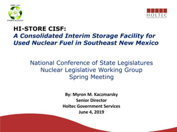
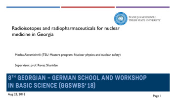
11/6/201449Control of DeflectionsReference: Sec. 9.5.2Minimum thickness stipulated in Table 9.5(b) shall apply for one-wayconstruction, unless calculation of deflection indicates a lesser thicknesscan be used without adverse effects.WEBINAR50Serviceability – Deflection Post-cracking Stagebec (comp)f c (comp)N.A.hAsdc t (tens.)ft (tens)f t frfc 0.5 f c Concrete Beam ElevationWEBINAR25
11/6/201451DeflectionReference: Sec. 9.5.2.3Effective stiffness for beams and one wayconstructionIe (Mcr/Ma)3 Ig [1-(Mcr/Ma)3]Icr Eq. (9 - 10)WhereMcr fr Ig /ytfr 7.5 f c Ec 57000 f c Eq. (9 – 11)Eq. (9 – 12)For Normal Weight ConcreteWEBINAR52Serviceability – Deflection Post-serviceability Cracking StageLoss in stiffness of sectionExtensive crackingYielding in flexural reinforcement steelIncrease deflection Limit State of Deflection BehaviorCracks continue to openNeutral axis rise upwardTotal crushing of concrete when rupture occursWEBINAR26
11/6/201453DeflectionReference: Sec. 9.5.2.5 Long-term Deflection - resulting from creep andshrinkage:Multiply immediate deflection due to sustained loads byλ / (1 50 ')Eq. (9-13)Whereλ Multiplier for additional long-term deflection Time dependent factor for sustained load ' A's /bd compression steel ratioTime 5 years12 months6 months3 months 2.01.41.21.0WEBINAR54Control of DeflectionsWEBINAR27
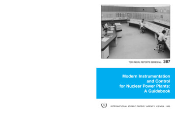
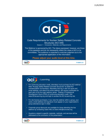
11/6/201455CHAPTER 10FLEXURE AND AXIAL LOADSWEBINAR56BASIC STRENGTH DESIGN RELATIONSHIPReference: Sec. 10.2.2 ASSUMPTION (1)Strain in reinforcement and concrete shall beassumed directly proportional to the distance fromthe neutral axis.bwA's cd' 'scn.a. cd-d'A'sn.a.dd-cAsAs sTension faced'1 's1d'2 's2d-d'1 s2d-ccd s1Tension faceWEBINAR28
11/6/201457BASIC STRENGTH DESIGN RELATIONSHIPReference: Sec. 10.2.3 ASSUMPTION (2)Maximum usable strain at extreme concretecompression fiber shall be assumed equal to ecu 0.003bw0.85f c cu 0.003n.a.dcCn.a.d-cAsT sNote: cu based oncrushing ofconcrete observedin tests varies from0.003 to over0.008 with majoritybetween 0.003 to0.004Tension faceWEBINARBASIC STRENGTH DESIGN RELATIONSHIP58Reference: Sec. 10.2.4 ASSUMPTION (3)Stress in reinforcement below the yield strength fy shall be takenas Es times the steel strain (fs Es εs)For strains greater than
The format of this Code is based and depends on the ACI 318-08 Code requirements and Commentary. This Code should be used in conjunction with ACI 318-08. The philosophy of ACI 349 is to assure general elastic seismic response whereas ACI 318 permits large inela