Transcription
CALIFORNIAENERGYCOMMISSIONCONSULTANT REPORTA GUIDE TO PHOTOVOLTAIC (PV)SYSTEM DESIGN AND INSTALLATIONJUNE 2001500-01-020Gray Davis, Governor
PV Installation GuideA GUIDE TO PHOTOVOLTAIC (PV)SYSTEM DESIGN AND INSTALLATIONPrepared for:California Energy CommissionEnergy Technology Development Division1516 Ninth StreetSacramento, California 95814Prepared by:Endecon Engineering347 Norris CourtSan Ramon, California 94583withRegional Economic Research, Inc.1104 Main Street, Suite 630Vancouver, Washington 98660Version 1.0June 14, 2001June 2001Page 1
PV Installation GuidePREFACEThe California Energy Commission is providing this guide as an information resource to those installingphotovoltaic (PV) systems under the Emerging Renewables Buydown Program. This is the first publisheddraft of this guide and represents the current state-of-the-art in PV system installation. Revisions will bemade to the document as necessary to address suggestions made by users of the guide. If anyone hassuggestions on how to make this guide more useful, please do not hesitate to send those suggestions to theCalifornia Energy Commission. We hope that this guide is a worthwhile addition to the resources availablefor installers and look forward to your constructive comments for continued improvements.June 2001Page 2
PV Installation GuideTABLE OF CONTENTSSECTION 1: INTRODUCTION. 41.1. Basic Principles to Follow When Designing a Quality PV System . 41.2. Basic Steps to Follow When Installing a PV System . 4SECTION 2: SYSTEM DESIGN CONSIDERATIONS . 52.1 Typical System Designs and Options. 52.1.1. Grid-Interactive Only (No Battery Backup). 52.1.2. Grid-Interactive With Battery Backup. 52.2. Mounting Options . 62.2.1. Roof mount. 62.2.2. Shade Structure . 72.2.3. Building-Integrated PV Array (BIPV). 72.3 Estimating System Output . 82.3.1. Factors Affecting Output . 82.3.2. Estimating System Energy Output . 92.4. Installation Labor Effort . 102.5. Incentives to Reduce Costs . 102.6. Estimating Electrical Energy Savings . 102.7. Supplier and System Qualifications . 102.7.1. Pre-Engineered Systems . 102.7.2. Warranties . 112.7.3. Company Reputation (years in business, previous projects). 112.8. Overall Project Coordination . 122.8.1. Utility Considerations . 122.8.2. Acceptance of Systems (performance evaluation) . 122.8.3. System Documentation . 122.8.4. System Monitoring . 122.9. References. 13SECTION 3: SYSTEM INSTALLATION . 143.1. General Recommendations . 143.1.1. Materials recommendations . 143.1.2. Equipment recommendations and installation methods . 143.2. PV System Design And Installation . 143.2.1. Preparation Phase . 143.2.2. Design Phase. 153.2.3. Installation Phase. 163.2.4. Maintenance and Operation Phase . 19SECTION 4: SOLAR ELECTRIC (PV) SYSTEM INSTALLATION CHECKLIST . 20APPENDIX. 25June 2001Page 3
PV Installation GuideSECTION 1: INTRODUCTIONPhotovoltaic (PV) power systems convert sunlight directly into electricity. A residential PV power systemenables a homeowner to generate some or all of their daily electrical energy demand on their own roof,exchanging daytime excess power for future energy needs (i.e. nighttime usage). The house remainsconnected to the electric utility at all times, so any power needed above what the solar system can produceis simply drawn from the utility. PV systems can also include battery backup or uninterruptible power supply(UPS) capability to operate selected circuits in the residence for hours or days during a utility outage.The purpose of this document is to provide tools and guidelines for the installer to help ensure thatresidential photovoltaic power systems are properly specified and installed, resulting in a system thatoperates to its design potential. This document sets out key criteria that describe a quality system, and keydesign and installation considerations that should be met to achieve this goal. This document deals withsystems located on residences that are connected to utility power, and does not address the special issuesof homes that are remote from utility power.In this early stage of marketing solar electric power systems to the residential market, it is advisable for aninstaller to work with well established firms that have complete, pre-engineered packaged solutions thataccommodate variations in models, rather than custom designing custom systems. Once a system designhas been chosen, attention to installation detail is critically important. Recent studies have found that 10-20%of new PV installations have serious installation problems that will result in significantly decreasedperformance. In many of these cases, the performance shortfalls could have been eliminated with properattention to the details of the installation.1.1. Basic Principles to Follow When Designing a Quality PV System1. Select a packaged system that meets the owner's needs. Customer criteria for a system may includereduction in monthly electricity bill, environmental benefits, desire for backup power, initial budgetconstraints, etc. Size and orient the PV array to provide the expected electrical power and energy.2. Ensure the roof area or other installation site is capable of handling the desired system size.3. Specify sunlight and weather resistant materials for all outdoor equipment.4. Locate the array to minimize shading from foliage, vent pipes, and adjacent structures.5. Design the system in compliance with all applicable building and electrical codes.6. Design the system with a minimum of electrical losses due to wiring, fuses, switches, and inverters.7. Properly house and manage the battery system, should batteries be required.8. Ensure the design meets local utility interconnection requirements.1.2. Basic Steps to Follow When Installing a PV System1. Ensure the roof area or other installation site is capable of handling the desired system size.2. If roof mounted, verify that the roof is capable of handling additional weight of PV system. Augment roofstructure as necessary.3. Properly seal any roof penetrations with roofing industry approved sealing methods.4. Install equipment according to manufacturers specifications, using installation requirements andprocedures from the manufacturers' specifications.5. Properly ground the system parts to reduce the threat of shock hazards and induced surges.6. Check for proper PV system operation by following the checkout procedures on the PV SystemInstallation Checklist.7. Ensure the design meets local utility interconnection requirements8. Have final inspections completed by the Authority Having Jurisdiction (AHJ) and the utility (if required).June 2001Page 4
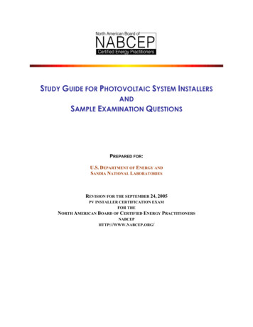
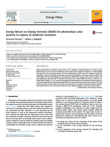
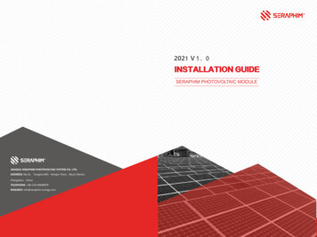
PV Installation GuideSECTION 2: SYSTEM DESIGN CONSIDERATIONS2.1 Typical System Designs and OptionsPV Electrical System TypesThere are two general types of electrical designs for PV power systems for homes; systems that interact withthe utility power grid and have no battery backup capability; and systems that interact and includebattery backup as well.2.1.1. Grid-Interactive Only (No Battery Backup)This type of system only operates when the utility is available. Since utility outages are rare, this system willnormally provide the greatest amount of bill savings to the customer per dollar of investment.However, in the event of an outage, the system is designed to shut down until utility power isrestored.Typical System Components:PV Array: A PV Array is made up of PV modules, which are environmentally-sealed collections of PV Cells—the devices that convert sunlight to electricity. The most common PV module that is 5-to-25 square2feet in size and weighs about 3-4 lbs./ft . Often sets of four or more smaller modules are framed orattached together by struts in what is called a panel. This panel is typically around 20-35 square feetin area for ease of handling on a roof. This allows some assembly and wiring functions to be doneon the ground if called for by the installation instructions.balance of system equipment (BOS): BOS includes mounting systems and wiring systems used to integratethe solar modules into the structural and electrical systems of the home. The wiring systems includedisconnects for the dc and ac sides of the inverter, ground-fault protection, and overcurrentprotection for the solar modules. Most systems include a combiner board of some kind since mostmodules require fusing for each module source circuit. Some inverters include this fusing andcombining function within the inverter enclosure.dc-ac inverter: This is the device that takes the dc power from the PV array and converts it into standard acpower used by the house appliances.metering: This includes meters to provide indication of system performance. Some meters can indicate homeenergy usage.other components: utility switch (depending on local utility)PV ArrayPV ArrayCircuitCombinerMain eractive PV System w/o Battery Backup2.1.2. Grid-Interactive With Battery BackupThis type of system incorporates energy storage in the form of a battery to keep “critical load” circuits in thehouse operating during a utility outage. When an outage occurs the unit disconnects from theutility and powers specific circuits in the home. These critical load circuits are wired from aJune 2001Page 5
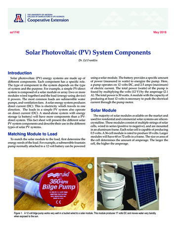
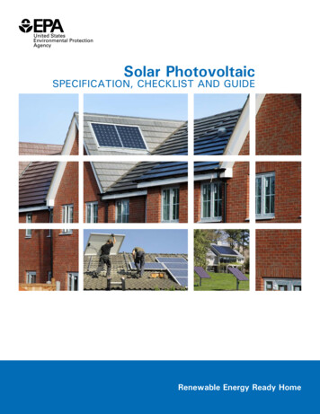
PV Installation Guidesubpanel that is separate from the rest of the electrical circuits. If the outage occurs during daylighthours, the PV array is able to assist the battery in supplying the house loads. If the outage occursat night, the battery supplies the load. The amount of time critical loads can operate depends onthe amount of power they consume and the energy stored in the battery system. A typical backupbattery system may provide about 8kWh of energy storage at an 8-hour discharge rate, whichmeans that the battery will operate a 1-kW load for 8 hours. A 1-kW load is the average usage fora home when not running an air conditioner.Typical System Components:In addition to components listed in 2.1.1., a battery backup system may include some or all of thefollowing:1. batteries and battery enclosures2. Battery charge controller3. separate subpanel(s) for critical load circuitsCritical LoadSub-PanelPV ArrayPV ArrayCircuitCombinerBackupBattery Ground-FaultPV Array ChargeProtectorSwitch ControllerMain ityBatterySystem2.2. Mounting OptionsThere are several ways to install a PV array at a residence.Most PV systems produce 5-to-10 Watts per square foot ofarray area. This is based on a variety of different technologiesand the varying efficiency of different PV products. A typical 2kW PV system will need 200-400 square feet of unobstructedarea to site the system. Consideration should also be given foraccess to the system. This access space can add up to 20% ofneeded area to the mounting area required.2.2.1. Roof mountOften the most convenient and appropriate place toput the PV array is on the roof of the building. ThePV array may be mounted above and parallel tothe roof surface with a standoff of several inches forcooling purposes. Sometimes, such as with flat roofs,June 2001Figure 1 Roof Mounted PV SystemPage 6
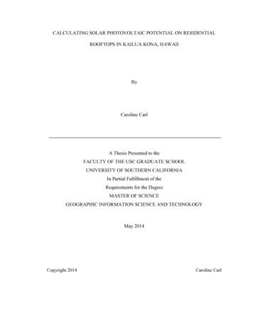
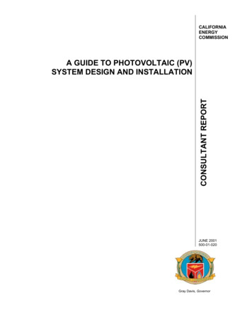
PV Installation Guidea separate structure with a more optimal tilt angle is mounted on the roof.Proper roof mounting can be labor intensive. Particular attention must be paid to the roofstructure and the weather sealing of roof penetrations. It is typical to have one support bracketfor every 100 Watts of PV modules. For new construction, support brackets are usually mountedafter the roof decking is applied and before the roofing materials is installed. The crew in chargeof laying out the array mounting system normally installs the brackets. The roofing contractorcan then flash around the brackets as they install the roof. A simple installation detail and asample of the support bracket is often all that is needed for a roofing contractor to estimate theflashing cost.Masonry roofs are often structurally designed near the limit of their weight-bearing capacity. Inthis case, the roof structure must either be enhanced to handle the additional weight of the PVsystem or the masonry roof transitioned to composition shingles in the area where the PV arrayis to be mounted. By transitioning to a lighter roofing product, there is no need to reinforce theroof structure since the combined weight of composite shingles and PV array is usually less thanthe displaced masonry product.2.2.2. Shade StructureAn alternative to roof mounting is to mount the system as ashade structure. A shade structure may be a patio cover ordeck shade trellis where the PV array becomes the shade.These shade systems can support small to large PVsystems.The construction cost with a PV system is a little differentthan for a standard patio cover, especially if the PV array isacts as part or the entire shade roof. If the PV array ismounted at a steeper angle than a typical shade structure,additional structural enhancements may be necessary tohandle the additional wind loads. The weight of the PV array2is 3-to-5 lbs./ft , which is well within structural limits of mostshade support structures. The avoided cost of installing roofbrackets and the associated labor could be counted towardthe cost of a fully constructed patio cover. The overall cost ofthis option will likely be higher than roof mounting, but thevalue of the shade often offsets the additional costs. Otherissues to consider include Figure 2 Patio Cover or Deck ShadeSimplified array access formaintenanceModule wiring, if visible fromunderneath, must be carefullyconcealed to keep the installationaesthetically pleasingCannot grow vines, or must bediligent about keeping it trimmedback from modules and wiring2.2.3. Building-Integrated PV Array (BIPV)Figure 3 Building-Integrated InstallationAnother type of system displaces some of theconventional roofing product with buildingintegrated PV modules. Commercially available products currently include roof slates (similar tomasonry roofing) and standing seam metal roofing products. Special attention must be paid toensure that these products are installed properly and carry the necessary fire ratings.June 2001Page 7
PV Installation GuideDimensional tolerances are critical and installation requirements must followed precisely to avoidroof leaks.2.3 Estimating System OutputPV systems produce power in proportion to the intensity of sunlight striking the solar array surface. Theintensity of light on a surface varies throughout a day, as well as day to day, so the actual output of a solarpower system can vary substantial. There are other factors that affect the output of a solar power system.These factors need to be understood so that the customer has realistic expectations of overall system outputand economic benefits under variable weather conditions over time.2.3.1. Factors Affecting OutputStandard Test ConditionsSolar modules produce dc electricity. The dc output of solar modules is rated by manufacturers underStandard Test Conditions (STC). These conditions are easily recreated in a factory, and allow for consistentcomparisons of products, but need to be modified to estimate output under common outdoor operatingo2conditions. STC conditions are: solar cell temperature 25 C; solar irradiance (intensity) 1000 W/m(often referred to as peak sunlight intensity, comparable to clear summer noon time intensity); and solarspectrum as filtered by passing through 1.5 thickness of atmosphere (ASTM Standard Spectrum). Amanufacturer may rate a particular solar module output at 100 Watts of power under STC, and call theproduct a “100-watt solar module.” This module will often have a production tolerance of /-5% of the rating,which means that the module can produce 95 Watts and still be called a “100-watt module.” To beconservative, it is best to use the low end of the power output spectrum as a starting point (95 Watts for a100-watt module).TemperatureModule output power reduces as module temperature increases. When operating on a roof, a solar moduleowill heat up substantially, reaching inner temperatures of 50-75 C. For crystalline modules, a typicaltemperature reduction factor recommended by the CEC is 89% or 0.89. So the “100-watt” module willtypically operate at about 85 Watts (95 Watts x 0.89 85 Watts) in the middle of a spring or fall day, underfull sunlight conditions.Dirt and dustDirt and dust can accumulate on the solar module surface, blocking some of the sunlight and reducingoutput. Much of California has a rainy season and a dry season. Although typical dirt and dust is cleaned offduring every rainy season, it is more realistic to estimate system output taking into account the reduction dueto dust buildup in the dry season. A typical annual dust reduction factor to use is 93% or 0.93. So the “100watt module,” operating with some accumulated dust may operate on average at about 79 Watts (85 Watts x0.93 79 Watts).Mismatch and wiring lossesThe maximum power output of the total PV array is always less than the sum of the maximum output of theindividual modules. This difference is a result of slight inconsistencies in performance from one module tothe next and is called module mismatch and amounts to at least a 2% loss in system power. Power is alsolost to resistance in the system wiring. These losses should be kept to a minimum but it is difficult to keepthese losses below 3% for the system. A reasonable reduction factor for these losses is 95% or 0.95.Dc to ac conversion lossesThe dc power generated by the solar module must be converted into common household ac power using aninverter. Some power is lost in the conversion process, and there are additional losses in the wires from therooftop array down to the inverter and out to the house panel. Modern inverters commonly used in residentialPV power systems have peak efficiencies of 92-94% indicated by their manufacturers, but these again areJune 2001Page 8
PV Installation Guidemeasured under well-controlled factory conditions. Actual field conditions usually result in overall dc-to-acconversion efficiencies of about 88-92%, with 90% or 0.90 a reasonable compromise.So the “100-watt module” output, reduced by production tolerance, heat, dust, wiring, ac conversion, andother losses will translate into about 68 Watts of AC power delivered to the house panel during the middle ofa clear day (100 Watts x 0.95 x 0.89 x 0.93 x 0.95 x 0.90 67 Watts).2.3.2. Estimating System Energy OutputFlatSouth0.89SSE,SSW 0.89SE, SW0.89ESE,WSW 0.89E, W0.894:120.970.970.950.920.887:12 12:12 21:12 Vertical1.00 0.97 0.89 0.580.99 0.96 0.88 0.590.96 0.93 0.85 0.600.91 0.87 0.79 0.570.84 0.78 0.70 0.52Sun angle and house orientationDuring the course of a day, the angle of sunlightstriking the solar module will change, which will affectthe power output. The output from the “100-wattmodule” will rise from zero gradually during dawnhours, and increase with the sun angle to its peakTable 1: Orientation Factors for Variousoutput at midday, and then gradually decrease intoRoof Pitches and Directionsthe afternoon and back down to zero at night. Whilethis variation is due in part to the changing intensity of the sun, the changing sun angle (relative to themodules) also has an effectThe pitch of the roof will affect the sun angle on the module surface, as will the East-West orientation of theroof. These effects are summarized in Table 1, which shows that an array on a 7:12-pitch roof facing dueSouth in Southern California gives, for example, the greatest output (correction factor of 1.00), while an Eastfacing roof at that same pitch would yield about 84% of the annual energy of the South facing roof (acorrection factor of 0.84 from Table 1).Table 2 is intended to give a conservative estimate of theannual energy expected from a typical PV system, takinginto account the various factors discussed above.These values are for annual kWh produced from a 1-kilowatt(1kW) STC DC array, as a simple and easy guide. If thesystem includes battery backup the output may be reducedfurther by 6-10% due to battery effects.CITYArcataShastaSan FranciscoSacramentoFresnoSanta MariaBarstowLos AngelesSan DiegokWh/kWstc (range)1092 - 13651345 - 16811379 - 17241455 - 18191505 - 18811422 - 17781646 - 20581406 - 17581406 - 1758Example: A 4 kW STC solar array (as specified under STCconditions) located in the Los Angeles area at a 4:12 pitchand facing southeast should produce at least 5343 kWh ofelectric energy annually (1406 kWh/kW x 0.95 x 4 kW Table 2: Annual Energy Production5343 kWh). The typical residential customer in that areaby City per kWSTC array rating1uses about 7300 kWh annually , meaning such a PV systemcould produce at least 75% of the total energy needed by such atypical home. And if energy efficiency measures were taken by the owner to reduce the overall electricalconsumption of the home, the percentage could approach 100%. Note that the low end of the range wasused to calculate the actual savings. It is wise to be conservative when making performance claims.Net metering has recently been extended to time-of-use customers yielding a potential additional value of20-30% for the PV electricity generated by the system. With this net time-of-use metering, the homeownerwould cover almost their entire electric bill and only have to pay the monthly metering charge.1Actual residential electrical energy usage varies dramatically from one home to the next. It is best to use the previoustwo years of energy bills to determine actual energy consumption for a particular home. Energy consumption in Californiacan vary from 3,000 kWh/year for a very minimal user to 25,000 kWh/year for a large home with heavy electrical usage.June 2001Page 9
PV Installation Guide2.4. Installation Labor EffortInstallation effort is very sensitive to specific house layouts and roofing type. An experienced crew caninstall a 2 kW non-battery PV system in two-to-four person-days. Systems with large solar arrays arerelatively less effort per watt of power and kWh of energy than smaller systems because the installation ofthe inverter and other hardware required by all PV systems is spread over more solar modules. Systemswith battery backup are more labor intensive than non-battery systems because of the additional wiringrequired for wiring the critical load subpanel. A battery system can add 50-100% to the time required for theinstallation.2.5. Incentives to Reduce CostsFinancial incentives are available from the Energy Commission, the CPUC, and several local utilities andmunicipalities throughout California to reduce these system costs. The CEC buydowns are calculated bymultiplying 4.50 times the adjusted peak dc power from the system in Watts (up to a maximum of 50% ofthe system cost). This buydown is available for all Pacific Gas & Electric (PG&E), Southern California Edison(SCE), and San Diego Gas & Electric (SDG&E) customers. Some municipal utilities in cities such asSacramento, Los Angeles, Palo Alto, and Roseville provide the same or even higher incentives.This level of rebate can reduce the cost of systems by 30 to 50 percent or more and result in much morefavorable economics for the owner. An owner can incorporate a basic 1 kW solar power system for as littleas 3,000- 5,000. If the system is included in the mortgage of the home, this small increment in housepayment may be offset by an equivalent reduction in the monthly utility bill.2.6. Estimating Electrical Energy SavingsOne of the key benefits of residential solar power systems is a lower electric utility bill resulting from theenergy that the solar system produces. The energy savings to a homeowner can be estimated by simplymultiplying the annual energy in kWh that a PV system might produce times the utility electric energy rate.These rates vary by local utility, and are likely to increase from their current values. Estimated energysavings from small and large PV systems in Southern California are presented below to illustrate the kinds ofsavings that can be achieves.Sample Annual Electric Utility Bill SavingsUtility Electric Energy RateSolarEstimatedArrayAnnual 0.10 /kWh 0.15 /kWh 0.20 /kWh(STC)Energy1.2 kW1687 kWh 168.70 224.93 337.404.0 kW5624 kWh 562.40 843.60 1,124.80 0.25 /kWh 421.75 1406.002.7. Supplier and System QualificationsWhen choosing a supplier and specifying a PV system, the following are a series of general guidelines to helpguide the decision-making process.2.7.1. Pre-Engineered SystemsWhen a owner considers an HVAC system for a home, they do not buy a compressor from one manufacturerand a cooling coil from another company, and a fan from a third company and then put these pieces together.The equipment manufacturers have engineered a packaged system that is designed to work together. Eachmodel of a home may need a slightly different unit based on the size and layout, but those variations have beenJune 2001Page 10
PV Installation Guidedesigned into the product. In the same way, the components of a PV system should be engineered to worktogether as a unit accounting for variations in system size for different homes.Since the PV industry is in the early stages of development, there is a wide range of competency levels amongPV system integrators. Unless the installer is familiar enough with the technology to recognize whether thesystem integrator is competent, it is much safer to stay with a firm that provides pre-engineered systems. Preengineering may not guarantee a flawless system, but the concerns over product compatibility and specificationof individual components have been addressed in the system design.2.7.2. WarrantiesThere are several types of warranties that come with a system or can be purchased in addition to a standardwarranty. These include (1) product warranties covering defects in manufacture; (2) system warranties coveringproper operation of equipment for a specific time period (5 or 10 years); and, (3) annual energy performancewarranties covering the guaranteed output of the PV system. The installer, to guarantee proper systeminstallation, often covers the system and annual energy performance warranties.Product warranties:It is common these days to see warranties on PV modules of 20 or more years. Although this is impressive andindicates the level of confidence manufacturers place in the longevity of their products, there are many othercomponents in these systems that may not have the same
Jun 14, 2001 · 5. Design the system in compliance with all applicable building and electrical codes. 6. Design the system with a minimum of electrical losses due to wiring, fuses, switches, and inverters. 7. Properly house and manage the battery system, should batteries be required. 8. Ensure the desi