Transcription
1 1.0SERAPHIM PHOTOVOLTAIC MODULEJIANGSU SERAPHIM PHOTOVOLTAIC SYSTEM CO. LTD.ADDRESS: No.10, TongshunRD,Henglin Town,Wujin District,Changzhou,ChinaTELEPHONE: 86-519-69699879MAILBOX: info@seraphim-energy.com
INSTALLATION GUIDE FOR SERAPHIMPHOTOVOLTAIC MODULEINSTALLATION GUIDE FOR SERAPHIMPHOTOVOLTAIC MODULE 163104& 0' 5)*4 (6*%&Thanks for choosing Seraphim Photovoltaic Modules (hereafter referred to as“PV Module”), This Guide is to give information on how to apply SeraphimPVmodules properly. The PV modules shall be properly grounded in accordance with the instructions in this Guide or the requirements of the National Electrical Code. Installing PV modules requires specialized skills and knowledge. Installationshould only be performed by qualified personnel, electrical connectionsXKW[OXKY G ROIKTYKJ KRKIZXOIOGTͫ]NKXK GVVROIGHRK GIIUXJOTM ZU RUIGR IUJK GTJInstallers must read and understand this Guide prior to installation. For anylaw (i.e. the NEC for the USA and CEC for Canada).questions, please contact our technical department (technic@seraphim-ener- Installers should assume all risks of injury that might occur during installation,gy.com) for further information. Installers should follow all safety precautionsincluding, but not limited to, the risk of electric shock.described in this Guide as well as local codes when installing a module.Keep this Guide in a safe place for future reference (care and maintenance) andin case of sale or disposal of the PV modules. "11-* "#-& 130%6 54This document is applicable to the series of PV modules as listed below: One single PV module may generate more than 30V DC when exposed todirect sunlight. Access to a DC voltage of 30V or more is potentially hazardous. PV modules convert light energy to DC electrical energy, which are designedfor outdoor use. PV modules can be mounted onto ground, rooftop, vehicles orboats etc. The proper design of support structures lies within responsibility ofthe system designers and installers.Type 1SRP-XXX-6PA、 SRP-XXX-6PA-HV、 SRP-XXX-6MA、 SRP-XXX-6MA-HVType 2SRP-XXX-6PB、 SRP-XXX-6PB-HV、 SRP-XXX-6MB、 SRP-XXX-6MB-HVType 3SRP-XXX-BPZ、 SRP-XXX-6PZ-HV、 SRP-XXX-BMZ、 SRP-XXX-BMZ-HVType 4SRP-XXX-BPA、 SRP-XXX-BPA-HV、 SRP-XXX-BMA、 SRP-XXX-BMA-HVType 5SRP-XXX-BPB、 SRP-XXX-BPB-HV、 SRP-XXX-BMB、 SRP-XXX-BMB-HVType 6SRP-XXX-BPC、 SRP-XXX-BPC-HV、 SRP-XXX-BMC、 SRP-XXX-BMC-HV Only use equipment, connectors, wiring and support frames compatible withType RP-XXX-E11A-HVthe PV modules.Type RP-XXX-E11B-HVType 9SRP-XXX-BMD、SRP-XXX-BMD-HV45: ͬ. 3UJ[RKY ]OZN ; XXX:Module power Do not use mirrors or other magnifiers to concentrate sunlight onto the PVmodules. When installing the PV modules, abide to all local, regional and national statutory regulations. Obtain a building permit if necessary. Do not clean the modules with chemicals. )"/%-*/( 4"'&5: Do not lift the PV module by grasping the module’s junction box or 4"'&5:electrical leads. Do not stand or step on the PV modules or place heavy objects onto it. (&/&3"- 4"'&5: Do not drop the PV module or allow objects to fall on the PV module. The PV modules are qualified for application class A, which may be used in Do handle with care when move, transport and install the PV modules.systems operating at greater than 50 V DC or 240 W, where general contact Do not attempt to disassemble the PV modules, and do not remove anyaccess is anticipated. PV modules qualified for safety through this part of IEC61730 and IEC 61730-2 and within this application class are considered to meetthe requirements for safety class II.attached nameplates or components from the PV modules. Do not apply paint or adhesive to the PV module top surface. Do not scratch or hit the back sheet.2嗡163104& 0' 5)*4 (6*%&嗡4"'&5:4"'&5:嗡3
INSTALLATION GUIDE FOR SERAPHIMPHOTOVOLTAIC MODULEINSTALLATION GUIDE FOR SERAPHIMPHOTOVOLTAIC MODULE Do not drill holes in the frame. This may reduce the frame mechanical Under normal outdoor conditions the current and voltage generated willstrength and cause crack cells due to vibration.differ from those listed on the datasheet. When design systems, current and Do not break the anodized coating of the frame (except for grounding connection), this may cause corrosion of the frame. Do not use PV modules with broken glass or torn back sheet which hasdanger of electrical shock. Do not handle panels in wet condition unless has appropriate protection. Do not expose PV module to sunlight until installation to avoid unnecessarydegradation. During all the transportation, please make sure there is no strenuous vibrationon module. Because it may cause cell micro crack or damage the module. */45"--"5*0/ 4"'&5: Installation shall be in conformity with IEC standard, Safety Standard for Electrical Installations.short-circuit current should be multiplied by a factor of 1.25 to determine components ratings. Only use connectors compatible with the PV module connectors. Removingthe connectors without prior authorization will invalidate the warranty. Do not dismantle installed modules to another project, which may invalidatethe warranty. Do not install modules within 50m of the shoreline '*3& 4"'&5: The fire rating of this module is valid only this Guide is followed. Consult your local authority for Guidelines and requirements for building orstructural fire safety. Do not use PV modules near equipment or in places where flammable gases Do not disconnect under load.may be generated. Do not touch conductive parts of PV modules, such as terminals which can Follow local codes and laws when install the modulesresult in burns, sparks and lethal shock whether or not the PV module is connected. Do not touch the PV module unnecessarily during installation. 130%6 5 *%&/5*'* "5*0/ Do not work in the rain, snow or windy conditions.Each module has three Barcode stickers which have the same unique serial No. Do not expose the artificially sunlight to PV modules. Completely cover theof each module and one label sticker:PV module with an opaque material during installation to prevent electricity(GXIUJK 2GSOTGZKJ OTZU 6 SUJ[RKY from being generated. Do not wear metallic rings, watchbands, ear, nose, lip rings or other metallicobjects while installing or troubleshooting. Only use insulated tools that are qualified for working on electrical installations. Follow the safety regulations for all other system components, including wiresand cables, connectors, charging regulators, inverters, storage batteries,rechargeable batteries, etc.4嗡4"'&5:Barcode 2: Stick on the backside of PV modules.Barcode 3: Stick on the middle location of long Frame side.2GHKR 9ZOIQ UT ZNK HGIQYOJK UL 6 SUJ[RKY IUTZGOTY INGXGIZKXOYZOIY VGXGSKZKXY of the PV modules.Check the serial No. in the barcode with the packing list when unpacking. Provide PV module serial No. when you need support from SERAPHIM on particular PV modules.130%6 5 *%&/5*'* "5*0/ 嗡5
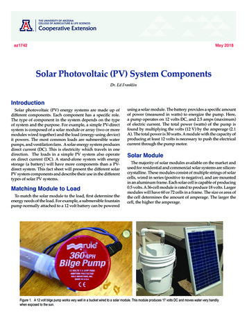
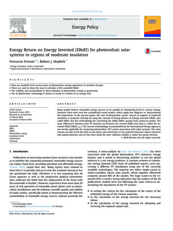
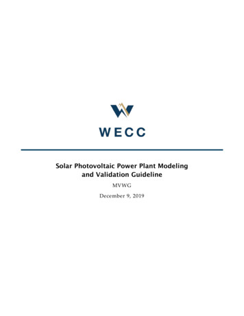
INSTALLATION GUIDE FOR SERAPHIMPHOTOVOLTAIC MODULE .& )"/* "- */45"--"5*0/INSTALLATION GUIDE FOR SERAPHIMPHOTOVOLTAIC MODULEDo not install the PV module in a location where it would be immersed in wateror constantly exposed to water from a sprinkler or fountain etc. (&/&3"- */45"--"5*0/ 13*/ *1-& 4 3&8 */45"--"5*0/ Module can be installed in both landscape and portrait modes【1】 [Each PV module has 8 mounting holes (shown as drawing 1).The downward It is recommended to install the same size and the same type of module in one PVmechanical load resistance of module would be different according to thearray.installation holes used(shown as table 1)Please use 8 of them tosecure the The PV modules shall be installed high enough to keep it away from potentialshading, flying sands, snow and water.modules to support structure. The module frame must be attached to a mounting rail using M8 corrosion-proof screws together with spring washers and flatwashers in eight symmetrical locations on the PV module. The applied torque It is recommended to install the PV modules 30cm away from the ground to makeshould be big enough to fix it steadily.The reference torque value for M8 screwsure ventilation.is 16 20N*m. Appropriate installation structures shall be chosen to meet required mechanicalload. It is recommended to install the PV modules with minimum angle of 10 degree tomake the dust easily to be washed off. It is recommended to keep minimum 10mm gap between PV modules for thermalexpansion of materials. Install PV modules appropriately according to corresponding mechanical load14need.9 -0 "5*0/ "/% "/(-& 4&-& 5*0/It is recommended to install PV modules where has excellent sunlight resources. In8 mounting holesthe Northern Hemisphere, the module should typically face south, and in the Southern Hemisphere, the modules should typically face north. The most optimistic installation angle varies according to different latitudes and longitudes; please consultexperts with appropriate knowledge background when determining the installationlocations and angles.When choosing a site, avoid trees, buildings or obstructions, which could cast shadows on the solar photovoltaic modules. Shading causes hotspot and loss of output,even though the factory fitted bypass diodes of the PV module will minimize sucheffect.Do not install the PV module near naked flame or flammable materials.%3"8*/( INSTALLED HOLES USED8 Installation HolesMECHANICAL LOAD5400Pa4 Installation Holes(Inner ones)2400Pa4 Nextracker Holes(only for 72 type module)2400PaTABLE 16嗡.& )"/* "- */45"--"5*0/7.& )"/* "- */45"--"5*0/ 嗡
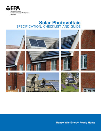
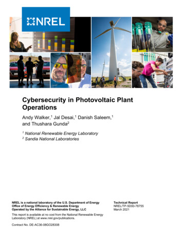
INSTALLATION GUIDE FOR SERAPHIMPHOTOVOLTAIC MODULE -".1 */45"--"5*0/INSTALLATION GUIDE FOR SERAPHIMPHOTOVOLTAIC DVK!VKG!XDBM!IBY!VKG!FKDHV!FAYG!DC!VKG!LDYZXG! AVKAB!VKG!ODBFVHIABVF!FKD B!AB!YHI ABM9!IBY!YHI ABMR 1970/19561665/1650/1640Clamplengthʈ mm992/1002ʈ mm1002ʈ mmZH!OXILJF6!*KG!LDYZXGF!IHG!bZAXV!VD! AVKFVIBY!I!YD B IHY!CDHOG!DC!ZJ!VD! S@@!0I![ @!UMlL9 !DH!9S@@!0I![9SS!UMlL9 !IOODHYABM!VD! KGHG!VKGN!IHG!OXILJGY(sh-Type3D B!IF!VIbXG9!IBY!VIbXGR 'AVG8FJGOACAO!XDIYF!FZOK!IF! ABY!DH!FBD ! KAOK!2288/2256 1134/1133LIN!GiGHV!CDHOGF!AB!I!YACCGHGBV! BVABM!DJVADB6!2180Type4209410381996/2015 992/100217554.4.1 .Install module with clamps at longsides of framesType5Type610381674/1690 992/100218521002 50mmʈ mmʈ mmʈ mmʈ mmType719411048/1066ʈ mmType816231048/1066ʈ mmType917071133ʈ 40019050054005"#-& 4.4.1 .Install module with clamps at short sides of frames%3"8*/( 8嗡.& )"/* "- */45"--"5*0/%3"8*/( 9.& )"/* "- */45"--"5*0/ 嗡
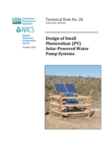
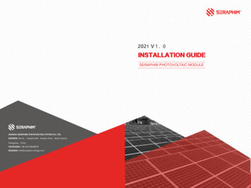
INSTALLATION GUIDE FOR SERAPHIMPHOTOVOLTAIC MODULETYPEc(mm)d(mm)INSTALLATION GUIDE FOR SERAPHIMPHOTOVOLTAIC MODULEClampslengthC(mm)D(mm)feature and the extreme low temperature of installation location must be takenLoads(Pa)into consideration when calculate the Voc of the PV string .The PV modules connected in parallel shall have similar Voltage. The Isc tem-Type11985/1970/1956 992/1002ʈ mm502482400perature coefficient feature and the extreme high temperature of installationType21665/992/10021650/1640ʈ mm502482400array.ʈ 6 1134/1133Type41996/2015 992/1002/2094/1038 50mmlocation must be taken into consideration when calculate the Isc of the PVPlease refer to local regulations to determine the system wires size, type andType517551674/16901038992/1002ʈ mm502482400Type618521002ʈ mm502482400Type719411048/1066ʈ mm502482400Type816231048/1066ʈ mm502482400Type917071133ʈ mm602802400temperature.The cross-sectional area and cable connector capacity must satisfy the maximum short-circuit of PV system (For a single component, we recommended thecross-sectional area of cables is 4mm2 and the the rated current of connectorsis more than 15A), otherwise cables and connectors will become overheatingfor large current. Please pay attention: the temperature limit of cables is 85 Cand the temperature limit of connector is 105 CA qualified system designer or integrator should always be consulted.Building permits, inspections and approvals by the local utility are generallyrequired.Before installation, make sure that the connector is well protected and thereshould be no foreign matter such as soil, sand and gravel in the connector. If any,it must be cleaned before installation. If the connector is damaged or deformed,the connector must be replaced before use; if there is no spare connector, please5"#-& contact seraphim in time.If conversion cable is needed, see attachment1 for details.Remark : &-& 53* "- */45"--"5*0/ (306/%*/(Where common grounding hardware (nuts, bolts, star washers, spilt-ring lockWARNING Electrical HazardThis module produces electricity when exposed to light. Follow all applicable electrical safety precautions.-ș 542? W[GROLOKJ VKXYUTTKR IGT OTYZGRR UX VKXLUXS SGOTZKTGTIK ]UXQ UT ZNKYK 6 modules. BE AWARE of dangerous high DC voltage when connecting module. DO NOT damage or scratch the rear surface of the module.washers, flat washers and the like) is used to attach a listed grounding/bondingdevice, the attachment must be made in conformance with the groundingdevice manufacturer’s instructions.For grounding and bonding requirements, please refer to regional and nationalsafety and electricity standards. If grounding is required, use a recommendedconnector type, or an equivalent, for the grounding wire.If grounding is required, the grounding wire must be properly fastened to the DO NOT handle or install module when they are wet.module frame to assure adequate electrical connection (grounding hole shownThe wiring components shall be compatible with the PV modules.as drawing 4).The PV modules connected in serial shall have similar current. The Voc of one PVWhen system operates in high humidity and high temperature circumstances,string shall no higher than the maximum system voltage(make reference to thetransformer-Based inverter allowing system negative grounding is highly rec-maximum system voltage marked on label), the Voc temperature coefficient10嗡&-& 53* "- */45"--"5*0/ommended to achieve mitigating risk of higher power degradation rate.(306/%*/(嗡11
INSTALLATION GUIDE FOR SERAPHIMPHOTOVOLTAIC MODULEINSTALLATION GUIDE FOR SERAPHIMPHOTOVOLTAIC stallation2XØ4ModuleType: VK %3"8*/( : VK ."*/5&/"/ &Clean the glass surface of the module regularly with clean water and a softsponge or cloth. A mild, non-abrasive cleaning agent may be used to remove: VK stubborn dirt.Water with high mineral content is not recommended to clean: VK the module.: VK5Check the electrical, grounding and mechanical connections every six monthsto verify that they are clean, secure, undamaged and free of corrosion.: VK6If any problem arises, consult a professional for suggestions.: VK9Caution: observe the maintenance instructions for all components used in thesystem, such as support frames, charging regulators, inverters, batteries etc. 1"3".&5&34: VK7The parameters may be updated time to time, accurate parameters pleasecheck on our website: http://www.seraphim-energy.com or email to our technical support team: technic@seraphim-energy.com.: VK84UZK :NOY \KXYOUT UL :; /TYZGRRGZOUT -[OJK GXK KLLKIZO\K LXUS 4U\ 9ͫ[TZORit is replaced by new version.12嗡."*/5&/"/ & * 1"3".&5&343&."3K 嗡13
ULEDUALGLASSPHOTOVOLTAICMODULEBefore installation, make sure that the connector is well protected and there (&/&3"- */45"--"5*0/ 13*/ *1-& (&/&3"- */45"--"5*0/ 13*/ *1-&shouldbe no foreign matter such as soil, sand and gravel in the connector. If any, -".1 */45"--"5*0/ -".1 */45"--"5*0/ REMARKor deformed,it must be cleaned before installation. If the connector is damaged【1】【1】 Modulecanbebeinstalledin inbothlandscapeandportrait ACHMENT1 modesthe connector must be replaced before use; if there is no spare connector, pleaseUSEOFCONVERSIONCABLES Theclampshallnotshadethefrontsideof ofthecells. . FORin nottimecontactseraphimThedualglassmoduleis isdesignedforforclampinstallation.It allation.needtheclampsThe schematic diagram is as igure1 andfigure2 showthestructurewithrubberstripsthebracket.Figure1 andfigure2 s. it itawayfrompotential ntialRemark :If conversion cable is needed, see attachment1 for details.Conversioncablesarerequiredto meet any of the following g,flyingsands,snowandwater.1. When the DC side input terminal of the inverter or combiner box is original MC4. It thegroundtotomakeIt dmake2. When the manufacturer of inverter or combiner box requires series DC input bussureventilation.sureventilation. ."*/5&/"/ &terminal must be MC4. It omthegroundororroofIt egroundroofLandscapeinstallationModuleType 4 41 12 2Portrait1 1installation 2 24 4Cleanthe glasssurfaceof dulerearside.maintaintheenergyyieldmodulerearside. with clean water and a softInspection before use:sponge or cloth. A mild, non-abrasive cleaning agent may be used to remove redmechanical uiredmechanical1.Confirmthe originalMC4 ibleMC4stubborn hanicalconnectionssixmonthsto to2.surethat the groundingconnectorontheconversioncableis not everydetachedor10loose, It ngleofof10degreeIt makethedusteasilywashed3. Confirm that the cable insulation layer of the conversion cable is not damaged,Ifanyproblemarises,toconsulta professionalforsuggestions. rforthermal isIt maland the cable is not severely bent or Caution: observe the maintenance instructions for all components used in nverters, batteriesetc. pondingmechanicalload ed.1.Theconversion cable installation position: the positive pole of the string is thepositive pole of the first component junction box cable in the string, and the nega 1"3".&5&34 -0 "5*0/ "/% "/(-& 4&-& 5*0/ -0 "5*0/ "/% "/(-& 4&-& 5*0/tivepole is the negative pole of the la
described in this Guide as well as local codes when installing a module. Keep this Guide in a safe place for future reference (care and maintenance) and in case of sale or disposal of the PV modules. "11-* "#-& 130%6 54 This document is applicable to the series of PV modul