Transcription
Mike Holt’s Illustrated Guide toDIRECTORY, IDENTIFICATION, LABEL,MARKING, PLAQUE, AND SIGNREQUIREMENTS FOR SOLAR PV SYSTEMSBased on the 2014 NEC Articles 690 and 705Extracted from Mike Holt’s UnderstandingNEC Requirements for Solar Photovoltaic SystemsFor more information on this or other training products,visit www.MikeHolt.com or call 888.632.2633Date: March 3, 2015
NOTICE TO THE READERThe publisher does not warrant or guarantee any of theproducts described herein or perform any independentanalysis in connection with any of the product informationcontained herein. The publisher does not assume, andexpressly disclaims, any obligation to obtain and includeinformation other than that provided to it by the manufacturer.The reader is expressly warned to consider and adopt allsafety precautions that might be indicated by the activitiesherein and to avoid all potential hazards. By following theinstructions contained herein, the reader willingly assumesall risks in connection with such instructions.The publisher makes no representation or warranties ofany kind, including but not limited to, the warranties of fitness for particular purpose or merchantability, nor are anysuch representations implied with respect to the materialset forth herein, and the publisher takes no responsibilitywith respect to such material. The publisher shall not beliable for any special, consequential, or exemplary damages resulting, in whole or part, from the reader’s use of,or reliance upon, this material.Author: Mike HoltTechnical Illustrator: Mike CulbreathCOPYRIGHT 2015 Charles Michael HoltProduced and Printed in the USAAll rights reserved. No part of this work covered by thecopyright hereon may be reproduced or used in any form orby any means graphic, electronic, or mechanical, includingphotocopying, recording, taping, or information storageand retrieval systems without the written permission ofthe publisher. You can request permission to use materialfrom this text by either calling 888.632.2633, e-mailingInfo@MikeHolt.com, or visiting www.MikeHolt.com.ABOUT THE AUTHORMike Holt worked his way up throughthe electrical trade. He began as anapprentice electrician and becameone of the most recognizedexperts in the world as it relatesto electrical power installations.He’s worked as a journeymanelectrician, master electrician, and electrical contractor.Mike’s experience in the realworld gives him a uniqueunderstanding of how the NECrelates to electrical installations from a practical standpoint.You’ll find his writing style to be direct, nontechnical,and powerful.Did you know Mike didn’t finish high school? Soif you struggled in high school or didn’t finish at all,don’t let it get you down. However, realizing that success depends on one’s continuing pursuit of education,Mike immediately attained his GED, and ultimatelyattended the University of Miami’s Graduate School fora Master’s degree in Business Administration.Mike resides in Central Florida, is the father of sevenchildren, has five grandchildren, and enjoys many outside interests and activities. He’s a nine-time NationalBarefoot Water-Ski Champion (1988, 1999, 2005–2009, 2012–2013). He’s set many national recordsand continues to train year-round at a World competition level (www.barefootwaterskier.com).What sets him apart from some is his commitmentto living a balanced lifestyle; placing God first, family,career, then self.For more information, call 888.NEC.CODE (632.2633), ore-mail Info@MikeHolt.com.NEC , NFPA 70 , NFPA 70E and National ElectricalCode are registered trademarks of the National FireProtection Association.This logo is a registered trademark of MikeHolt Enterprises, Inc.I dedicate this book to theLord Jesus Christ,my mentor and teacher.Proverbs 16:3
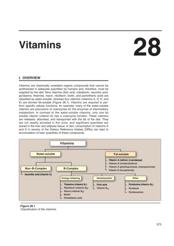
ARTICLE690SOLAR PHOTOVOLTAIC(PV) SYSTEMSIntroduction to Article 690—Solar Photovoltaic (PV) SystemsYou’ve seen, or maybe own, photocell-powered devices such as night lights, car coolers, and toys. These generally consist of a small solar module and a small light or motor. Typically, these run on less than 10V dc and draw only a fraction ofan ampere. These kinds of devices are very different from a system that can power a house or interconnect with a utility tooffset a building’s energy consumption.Consider the sheer size and weight of solar modules for providing electrical power to a building. You’re looking at mechanicaland site selection issues that may require specialized expertise. Structural and architectural issues must also be addressed.In summary, these installations are complicated and require expertise in several nonelectrical areas, which the NEC doesn’taddress.Article 690 focuses on reducing the electrical hazards that may arise from installing and operating a PV system, to the pointwhere it can be considered safe for property and people.This article consists of eight Parts and the general requirementsof Chapters 1 through 4 apply to these installations, except asspecifically modified by Article 690.Part I. General690.1 ScopeArticle 690 applies to PV electrical energy systems, array circuit(s),inverter(s), and charge controller(s) for PV systems. These systemsmay be interactive with other electrical power sources (electric utility,wind, generator) or stand-alone with or without energy storage (batteries). Figure 690–1FREE PDF—Solar Photovoltaic Systems 2014 NECFigure 690–13www.MikeHolt.com 888.NEC.CODE (632.2633)
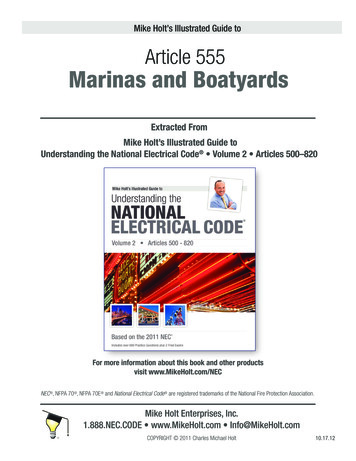
Article 690 Solar Photovoltaic (PV) Systems690.4 General Requirements(A) PV Systems. A PV system is permitted to supply power to a building in addition to any other electrical supply system(s).(B) Listed Equipment. Equipment for PV systems such as inverters,PV modules, dc combiners, dc-to-dc converters, and charge controllers must be listed for PV application. Figure 690–22Figure 690–23Ex: A directory isn’t required where all PV system disconnecting meansare grouped at the service disconnecting means.690.5 Ground-Fault ProtectionGrounded dc PV arrays must be provided with dc ground-fault protection meeting the requirements of 690.5(A) through (C) to reduce firehazards. Figure 690–24Figure 690–22Author’s Comment:nListing means that the equipment is in a list published by atesting laboratory acceptable to the authority having jurisdiction [Article 100].(C) Qualified Persons. PV systems, associated wiring, and interconnections must be installed by a qualified person. Figure 690–23Note: A qualified person has the knowledge related to construction andoperation of PV equipment and installations; along with safety training torecognize and avoid hazards to persons and property [Article 100].(D) Multiple Inverters. Where multiple utility-interactive inverters arelocated remote from each other, a directory is required at each dc PVsystem disconnecting means, ac disconnecting means for mini- andmicro-inverters, and service disconnecting means showing the location of all dc and ac PV system disconnecting means in the building/structure [705.10].FREE PDF—Solar Photovoltaic Systems 2014 NECFigure 690–244www.MikeHolt.com 888.NEC.CODE (632.2633)
Article 690 Solar Photovoltaic (PV) SystemsUngrounded dc PV arrays must be provided with dc ground-fault protection in accordance with 690.35(C).Ex: Ground-fault detection isn’t required for ground- or pole-mountedPV arrays with not more than two source circuits isolated from buildings. Figure 690–25Figure 690–26690.10 Stand-Alone Systems(A) Inverter Output. The ac current output from stand-alone inverter(s)must be no less than the rating of the largest single load connected tothe system.Figure 690–25(B) Sizing and Protection. Inverter ac output circuit conductors mustbe sized to the output rating of the inverter and have overcurrent protection in accordance with Article 240. The inverter ac output circuitovercurrent protection device must be located at the output of theinverter.(A) Ground-Fault Detection and Interruption (GFDI). The groundfault protection must:(1) Be capable of detecting a ground fault in the PV array dccurrent-carrying conductors and components, including any intentionally grounded conductors,(C) Single 120V Supply. The inverter output of a stand-alone PVsystem is permitted to supply a 120V single-phase, 3-wire, 120/240Vdistribution panelboard; however, 240V outlets or multiwire branch circuits aren’t permitted. The stand-alone PV system equipment mustbe permanently marked with the following words or equivalent with alabel that isn’t handwritten and is of sufficient durability to withstandthe environment involved [110.21(B)]:(2) Interrupt the flow of fault current,(3) Provide an indication of the fault, and,(4) Be listed for providing PV ground-fault protection.(C) Labels and Markings. A warning label that isn’t handwritten and is of sufficient durability to withstand the environmentinvolved, must be permanently affixed [110.21(B)] on the utilityinteractive inverter at a visible location at PV system batteries statingthe following: Figure 690–26WARNING—SINGLE 120-VOLT SUPPLY. DO NOTCONNECT MULTIWIRE BRANCH CIRCUITS!WARNING: ELECTRIC SHOCK HAZARD—IF A GROUNDFAULT IS INDICATED, NORMALLY GROUNDED CONDUCTORSMAY BE UNGROUNDED AND ENERGIZEDFREE PDF—Solar Photovoltaic Systems 2014 NEC(D) Energy Storage or Backup Power. Stand-alone PV systems aren’trequired to have energy storage power supplies.5www.MikeHolt.com 888.NEC.CODE (632.2633)
Article 690 Solar Photovoltaic (PV) Systems(E) Backfed Circuit Breakers. Circuit breakers that are back-fedmust be secured in place by a fastener that requires other than apull to release the breaker from the panelboard, if they’re fed from astand-alone or multimode inverter output in a stand-alone system. Circuit breakers marked “line” and “load” aren’t suitable for backfeed orreverse current. Figures 690–57 and 690–58Author’s Comment:nThe purpose of the breaker fastener is to prevent the circuit breaker from being accidentally removed from thepanelboard while energized, thereby exposing persons todangerous voltage.Part III. Disconnecting Means690.15 PV Equipment DisconnectPV equipment such as inverters, batteries, and charge controllers musthave a disconnecting means that opens all ungrounded circuit conductors from all sources of power. Figure 690–66Figure 690–57Figure 690–66Where equipment is energized from more than one source, such asan inverter supplied by dc current input from the array and ac currentoutput to the utility source, a disconnecting means is required for boththe dc input and ac output and they must be grouped and permanentlymarked and identified as to their purpose. Figure 690–67Figure 690–58A single disconnecting means in accordance with 690.17 is permittedfor the combined ac output of one or more inverters or ac modules inan interactive system.FREE PDF—Solar Photovoltaic Systems 2014 NEC6www.MikeHolt.com 888.NEC.CODE (632.2633)
Article 690 Solar Photovoltaic (PV) SystemsFigure 690–67Figure 690–68(A) Utility Interactive Inverters Not Readily Accessible. Utility interactive inverters installed outdoors that aren’t readily accessible mustcomply with the following:(1) The inverter dc input circuit disconnect must be within sight of andnot more than 50 ft away from the inverter.(2) The inverter ac output circuit disconnect must be within sight of theinverter and not more than 50 ft away from the inverter.(3) A disconnect for the inverter dc input circuit must be located eitheroutside the building, or inside nearest the point of dc input circuitconductor entry at a readily accessible location [690.13(A)].(4) A permanent directory must be installed denoting all electricpower sources on or in the premises at service equipment and allinverter ac output circuit disconnect(s) in accordance with 705.10.Figure 690–69(B) Equipment. PV source circuit isolating switches, overcurrent protection devices, and dc combiners are permitted on the PV side of thePV system dc disconnect. Figure 690–68690.16 Disconnecting Means for Fuses(C) DC Combiner Disconnect. DC combiners mounted on roofs musthave a load break disconnecting means located in or within 6 ft of thedc combiner. Figures 690–69 and 690–70(A) Disconnecting Means. A means must be provided to disconnecteach PV circuit fuse if energized from both directions. Figure 690–71Fuses for PV source circuits must be capable of being disconnectedindependently of fuses in other PV source circuits. Figure 690–72FREE PDF—Solar Photovoltaic Systems 2014 NEC7www.MikeHolt.com 888.NEC.CODE (632.2633)
Article 690 Solar Photovoltaic (PV) SystemsFigure 690–70Figure 690–72Figure 690–71Figure 690–73Author’s Comment:nWhere the output circuit fuse disconnect is located more than 6 ft fromthe fuses, a directory showing the location of each PV output circuit fusedisconnect must be installed at the fuse location.Tilt-out fuse holders meet the requirement for deenergizing the fuse as long as a load break switch is available at the PV source circuit combiner in accordance with690.15(C).Non-load-break-rated fuse disconnecting means must be marked “Donot open under load.” Figure 690–74(B) PV Output Circuit Fuse Disconnect. Where fuses for output circuits can’t be isolated from energized circuits, a disconnect thatcomplies with 690.17 must be located within sight of, or integral with,the PV output circuit fuse holder. Figure 690–73FREE PDF—Solar Photovoltaic Systems 2014 NEC8www.MikeHolt.com 888.NEC.CODE (632.2633)
Article 690 Solar Photovoltaic (PV) Systems(4) A PV enclosed switch marked for use in PV systems(5) A PV open-type switch marked for use in PV systems(6) A dc-rated molded-case circuit breaker suitable for backfeedoperation(7) A dc-rated, molded-case switch suitable for backfeed operation(8) A dc-rated enclosed switch(9) A dc-rated open-type switch(10) A dc-rated low-voltage power circuit breakerNote: Devices marked with “line” and “load” aren’t suitable for backfeedor reverse current.(B) Simultaneous Disconnect. The PV dc disconnect must simultaneously disconnec
NEC Requirements for Solar Photovoltaic Systems DIRECTORY, IDENTIFICATION, LABEL, MARKING, PLAQUE, AND SIGN REQUIREMENTS FOR SOLAR PV SYSTEMS Based on the 2014 NEC Mike Holt’s Illustrated Guide to For more information on this or other training products, visit www.MikeHolt.com or call 888.632.2633 Articles 690 and 705