Transcription
STUDY GUIDE FOR PHOTOVOLTAIC SYSTEM INSTALLERSANDSAMPLE EXAMINATION QUESTIONSPREPARED FOR:U.S. DEPARTMENT OF ENERGY ANDSANDIA NATIONAL LABORATORIESREVISION FOR THE SEPTEMBER 24, 2005PV INSTALLER CERTIFICATION EXAMFOR THENORTH AMERICAN BOARD OF CERTIFIED ENERGY PRACTITIONERSNABCEPHTTP://WWW.NABCEP.ORG/
TABLE OF CONTENTS1.INTRODUCTION . 12.REFERENCE RESOURCES AND ADDITIONAL READING MATERIALS . 32.12.23.REFERENCES: . 3ADDITIONAL READING MATERIAL:. 3PHOTOVOLTAIC (PV) INSTALLER STUDY GUIDE . 43.1WORKING SAFELY WITH PHOTOVOLTAIC (PV) SYSTEMS (TASKS 1.1 THRU 1.9 OF THE NABCEP TASK ANALYSIS)43.1.1OSHA Regulations. 43.1.2Safety in Attics . 53.1.3Working Space for Electrical Systems. 53.1.4How Photovoltaic Systems Work, and Associated Safety and Testing Issues. 63.2CONDUCTING A SITE ASSESSMENT (TASKS 2.1 THRU 2.10 OF THE NABCEP TASK ANALYSIS). 103.2.1Shading. 103.2.2Array Orientation . 133.2.3Array Location . 133.2.4Array Mounting Methods. 153.2.5 BOS Locations . 153.3SELECTING A SYSTEM DESIGN (TASKS 3.1 THRU 3.4 OF THE NABCEP TASK ANALYSIS) . 153.4ADAPTING THE MECHANICAL DESIGN (TASKS 4.1 AND 4.2 OF THE NABCEP TASK ANALYSIS) . 163.5ADAPTING THE ELECTRICAL DESIGN (TASKS 5.1 THRU 5.8 OF THE NABCEP TASK ANALYSIS) . 193.5.1Wire, Fuse, Circuit Breaker, and Disconnect Sizing . 203.5.1.1 Temperature and Conduit Fill Corrections for Ampacity of Conductors . 203.5.1.2 Voltage Drop for Circuits . 213.5.2Charge Controllers and Linear Current Boosters. 243.5.3Batteries and Battery Wiring. 273.5.4Inverters. 273.5.5Point-of-Utility Connection . 313.5.6Optional Standby System Panels . 323.5.7Grounding . 323.5.8Generators. 333.6INSTALLING SUBSYSTEMS AND COMPONENTS AT THE SITE (TASKS 6.1 THRU 6.10 OF THE NABCEP TASKANALYSIS) . 343.7PERFORMING A SYSTEM CHECKOUT AND INSPECTION (TASKS 7.1 THRU 7.8 OF THE NABCEP TASK ANALYSIS) 373.8MAINTAINING AND TROUBLESHOOTING A SYSTEM (TASKS 8.1 THRU 8.7 OF THE NABCEP TASK ANALYSIS). 404.STUDY GUIDE REVIEW QUESTIONS . 424.14.24.34.44.54.64.74.8WORKING SAFELY WITH PHOTOVOLTAIC SYSTEMS . 42CONDUCTING A SITE ASSESSMENT . 43SELECTING A SYSTEM DESIGN . 45ADAPTING THE MECHANICAL DESIGN . 46ADAPTING THE ELECTRICAL DESIGN . 47INSTALLING SYSTEMS AND SUBSYSTEMS AT THE SITE . 52PERFORMING A SYSTEM CHECKOUT AND INSPECTION . 53MAINTAINING AND TROUBLESHOOTING A SYSTEM. 545.ANSWER KEY TO STUDY GUIDE REVIEW QUESTIONS . 566.APPENDIX. 616.1IRRADIATION (FORMERLY CALLED INSOLATION) DATA FOR DENVER, CO . 61
DisclaimerInformation presented in this publication is intended to inform candidates as they prepare to apply for and complete the certification process for the Certified Solar Photovoltaic Installer Certification Program. While NABCEP has made a reasonable effort to provide current andaccurate information, neither NABCEP, nor its employees, volunteers, or representatives warrants or guarantees the accuracy,completeness, timeliness, merchantability, or fitness of the information contained herein for a particular purpose. Reference herein to anyspecific commercial product, process, training program, or service by trade name, trademark, manufacturer, or otherwise does not constituteor imply its endorsement, affiliation, or support by NABCEP or other contributors to this document. While individuals certified as a Certified Solar Photovoltaic Installer are required to meet established certification requirements, NABCEP maintains no control over thesecertificants or their related organizations, and disclaims all liability to any party for any action or decision made in reliance on the informationcontained herein or otherwise provided by NABCEP, or for any actions or inactions of candidates or certificants to any party, or for any lossor injury, resulting from the use or non-use of such information.
1.IntroductionThis Study Guide presents some of the basic cognitive material that individuals who install and maintain photovoltaic (PV)power systems should know and understand. This information is intended primarily as a Study Guide to help individualsbetter prepare for the NABCEP PV installer examination but does not provide all of the materials needed for completingthe certification examination. Knowledge of the information presented, knowledge of pertinent sections of the NationalElectrical Code and appropriate experience and qualifications are generally required of those applying for and completingthe NABCEP certification process. Applicants and certificants are also reminded that local installation codes can differfrom national codes and the information presented in this Guide.This Guide is based on a task analysis for the PV system installer, which includes the following eight major job/task areas:1.2.3.4.5.6.7.8.Working Safely with Photovoltaic SystemsConducting a Site AssessmentSelecting a System DesignAdapting the Mechanical DesignAdapting the Electrical DesignInstalling Subsystems and Components at the SitePerforming a System Checkout and InspectionMaintaining and Troubleshooting a System15%5%5%15%20%20%10%10%The percentage following each task area represents the approximate emphasis that each topic is given in this Guide, and issimilar to what would be expected for a typical distribution of emphasis in training programs and on formal testing forcertification and/or licensure in the trade.How this Guide is used may depend upon how much the reader already knows about installing PV systems. This Guide isorganized in the following manner: Reference Resources and Additional ReadingStudy GuideSample Examination QuestionsAnswer KeyThe Guide is intended to provide an overview of each of the major content areas of the above task analysis. A set ofpractice questions that relate to each of the major content areas is then provided. The questions are organized according toeach content area. The answers to the practice questions, along with related explanations, are given at the end of thisGuide. The experienced installer may wish to try the questions first. Then, if any are missed, s/he can study the answerkey to review the methods for solving the problems used by the technical experts who provided input to the authors of thisGuide. Individuals that are new to these topics likely will benefit most from starting at the beginning of the material andworking through to the end, answering questions after completing each section, but this Guide alone will neither ensure theapplicant will meet the requirements for taking the exam nor provide enough code-related information to successfullycomplete the exam.The sample examination questions span fundamental trade knowledge, codes and standards, and accepted industry practicein the relevant design, installation, and maintenance of PV systems. Many questions are based on system installationscenarios, requiring the use of schematics, diagrams, and equipment specifications. Guidelines for determining solutions tothe questions may be found in the text of this Guide, or from the references listed below. The suggested reading materialsare also listed to broaden resources for the applicant but have not been validated by legal entities or checked for accuracyby NABCEP.In addition to the specific content areas listed above, knowledge and skills in the following content areas are required forsuccessful completion of the examination:1Study Guide for the Applicant for NABCEP Photovoltaic Installer CertificationVersion 3 – August, 20051
Reading and interpreting plans and specificationsReading and interpreting codes and standardsUsing basic mathematics and some trigonometry (addition, subtraction, multiplication, division, calculations ofarea and volume, fractions, decimals, percentages, calculating the sides of triangles, square roots, powers ofnumbers, and solving simple algebraic equations for unknown variables)One does not need to understand algebra or calculus to be able to engage in safe work practices around PV systems, but it isuseful to better understand how PV systems work, to understand how to calculate expected system performance, and toevaluate the results of the system operation.Study Guide for the Applicant for NABCEP Photovoltaic Installer CertificationVersion 3 – August, 20052
2.Reference Resources and Additional Reading Materials2.1References:The following reference list identifies training materials, reports, and codes and standards associated with the design andinstallation of PV systems and are complementary to this Guide. Many of the sample questions come from thesereferences, as does other content in this Guide. Perhaps the most important reference on this list is the 2005 NationalElectrical Code (NEC), or its expanded 2005 National Electrical Code Handbook, and as so much of the material in thisGuide is based on the NEC, it is strongly encouraged that a copy be kept close at hand while reviewing this document.1.2001 Code of Federal Regulations, Chapter 29 Part 1926 - Safety and Health Regulations for Construction. U.S.Department of Labor/OSHA, OSHA Publications, P.O. Box 37535, Washington, D.C. 20013-7535http://www.osha.gov2.2005 National Electrical Code , NFPA 70, National Fire Protection Association, 1 Batterymarch Park, Quincy,MA 02269 (or 2005 National Electrical Code Handbook) http://www.nfpa.org/nec/2.2Additional Reading Material:1.Objectives and Task Analysis for the Solar Photovoltaic System Installer, North American Board of CertifiedEnergy Practitioners Technical Committee Document, Approved PVTaskAnalysis.pdf2.Photovoltaic Power Systems and the 2005 National Electrical Code: Suggested Practices, SAND2005-0342,February 2005, Sandia National Laboratories, Photovoltaic Systems Assistance Center, Albuquerque, NM 871850753 http://www.sandia.gov/pv. Also available in PDF format only from the Southwest Technology DevelopmentInstitute, s/PVnecSugPract.html3.A Guide to Photovoltaic System Design and Installation, California Energy Commission Consultant Report 50001-020, June 2001 http://www.energy.ca.gov/reports/2001-09-04 500-01-020.PDF4.Battery Service Manual, 11th Edition, Battery Council International, 401 North Michigan Avenue, Chicago, IL,60611 nstalling Photovoltaic Systems (Course Manual), 2002, Florida Solar Energy Center, 1679 Clearlake Road,Cocoa, FL 32922-5703 http://www.fsec.ucf.edu6.Working Safely with Photovoltaic Systems, January 1999. Sandia National Laboratories, Photovoltaic SystemsAssistance Center, Albuquerque, NM 87185-0753 http://www.sandia.gov/pv7.Maintenance and Operation of Stand-Alone Photovoltaic Systems, December 1991. Sandia National Laboratories,Photovoltaic Systems Assistance Center, Albuquerque, NM 87185-0753 http://www.sandia.gov/pv8.Stand-Alone Photovoltaic Systems: A Handbook of Recommended Design Practices, SAND87-7023. SandiaNational Laboratories, Photovoltaic Systems Assistance Center, Albuquerque, NM 87185-0753http://www.sandia.gov/pv9.Hybrid Power Systems: Issues and Answers. Sandia National Laboratories, Photovoltaic Systems AssistanceCenter, Albuquerque, NM 87185-0753 http://www.sandia.gov/pv10. The NRCA Roofing and Waterproofing Manual, 5th Edition, National Roofing Contractor’s sp?ProductID 24311. Home Power: The Hands-on Journal of Home-Made Power, Home Power, Inc., PO Box 520, Ashland, Oregon,www.homepower.comStudy Guide for the Applicant for NABCEP Photovoltaic Installer CertificationVersion 3 – August, 20053
3.Photovoltaic (PV) Installer Study Guide3.1Working Safely with Photovoltaic (PV) Systems (Tasks 1.1 thru 1.9 of the NABCEP Task Analysis)Working safely with PV systems requires a fundamental understanding of electrical systems coupled with common sense.The common sense aspects can be summed up with the following statements: If the workplace is cluttered, the possibility of tripping over something is significantly increased.If the workplace is a sloped roof with clutter, the possibility of falling off the roof is significantly increased.If tools are left lying out on a roof, the chance of them falling off the roof and injuring someone below is increased.If the workplace is a rooftop in bright sunshine, the chance of sunburn is increased, so a good layer of sunscreen is inorder.There are the usual subtle hazards, as well. These include nicks, cuts, and burns from sharp or hot components. Glovesshould be used when handling anything that might be sharp, hot, rough, or that might splinter. There is always thepossibility of dropping tools or materials on either oneself, someone else, or on sensitive equipment or materials. Droppingtools across battery terminals is an especially dangerous hazard. When a PV system is being assembled, it presents thepossibility of shock to personnel. Improperly installed systems may result in fire should an electrical short circuit occur.The surprise elements on the job site cannot be overlooked. There is nothing more disconcerting when trying to move to anew position on a roof, only to bump into someone who has quietly moved into the space that you had hoped to occupy. Itcan cause a loss of balance and result in a serious fall. When working in a potentially dangerous location, it is wise to keepa conversation going so workers know exactly where everyone is located.3.1.1OSHA RegulationsAll PV installers should be familiar with construction standards established by The Occupational Safety and HealthAdministration (OSHA), which are covered in Chapter 29 of the U.S. Code of Federal Regulations, Part 1926, Safety andHealth Regulations for Construction. Part 1926 consists of 26 subparts, labeled from A to Z. All parts are important, butsome parts, such as underwater construction, refer to situations that will not be encountered with typical PV installations.The OSHA rules most relevant to PV installations includeSubpart D Occupational Health and Environmental ControlsSubpart E – Personal Protective and Life Saving EquipmentSubpart I – Tools, Hand, and PowerSubpart K – ElectricalSubpart X – Stairways and LaddersSeveral especially pertinent issues relating to PV installations include the following: No construction worker will be required to perform work under conditions that are unsanitary, hazardous, ordangerous to his safety or health. 1926.10(a)The employer shall initiate and maintain a job site safety and health program. 1926.20(b)(1)The use of any machinery, tool, material, or equipment that is not in compliance with safety standards isprohibited. 1926.20(b)(3)Every employee shall be instructed in the recognition and avoidance of unsafe conditions. 1926.21(b)(2)Every employee shall be instructed in the safety and health regulations applicable to his/her work. 1926.21(b)(2)Falls are the leading cause of workplace fatalities, with 150–200 workers killed each year and nearly 10,000 injured.Because nearly every PV system involves climbing on a ladder, onto a roof, or both, it is essential that PV installers befamiliar with OSHA fall protection regulations. OSHA requires that fall protection must be provided where needed. Anywork done at more than six (6) feet above ground level must be done with fall protection considerations. Fall protectionsystems may include safety net systems, warning line systems, covers, toe boards, safety harnesses, or lanyards.Study Guide for the Applicant for NABCEP Photovoltaic Installer CertificationVersion 3 – August, 20054
In cases where no specific fall protection system is used, OSHA allows a safety monitoring system in which a person canoversee the operation provided that the person is Competent in recognition of fall hazards,Capable of warning other workers,Operating at the same level as the other workers where the other workers can be seen by the monitor,Close enough to the operations to communicate orally, andHaving no other distracting duties.Even when care is taken to ensure that no person falls, it is equally important to ensure that no tool or part is dropped. Ifthe object is dropped from overhead, anyone below is subject to having the object fall on him or her. Furthermore, theremay be scaffolds, lumber, or any number of other items on a job site capable of inflicting head or other bodily injury. Forthis reason, it is important to review Subpart E, where OSHA specifies foot protection, head protection, eye protection, faceprotection, and respiratory protection, in addition to fall protection practices.3.1.2Safety in AtticsSome PV installations may involve working in attic spaces. Working in an attic generally will require wearing a breathingmask, eye protection, clothing that will protect skin from insulation, and will require knowledge of where it is safe tosupport the weight of a person without risk of falling through the ceiling. It will also involve planning the excursion intothe attic to ensure that it will also be possible to get out of the attic. And adequate lighting will be needed in the confines ofthe attic. Before entering an attic, one should be sure to drink water for hydration if the attic is hot and if it is expected thatthe attic work will take more than 15 minutes.It is essential when traversing an attic to support one’s weight by stepping only on the ceiling joists or trusses. There maybe 1x2” furring strips for holding rock lath or plaster board, but these will not support the full weight of a worker. Theymay be confused with joists or trusses when they are covered with insulation. The ceiling material itself will definitely notsupport the weight of a worker. In many cases, planking or boards may be placed above joists temporarily to support theweight of workers in attics, making it easier to work.Care should be taken not to drop or lay heavy tools onto the ceiling material. It may crack the ceiling. Also, care should beexercized when climbing around wires, piping, air conditioning ductwork, and any other attic protrusions, such as recessedlighting fixtures. The recessed fixtures may be hot, and the other items are subject to damage if they are overstressed.Furthermore, wires, pipes, etc., present a tripping or choking hazard to the worker. Special care must be made to avoidcrushing air conditioning ductwork or existing electrical wiring. Caution is essential where protruding roofing nails maycatch on clothing or cause lacerations and punctures to the worker.3.1.3Working Space for Electrical SystemsThe National Electrical Code is very specific on the working spaces that must be accommodated for maintenance personnelto operate on equipment safely. Article 110.26 covers the requirements relative to working spaces. Rather than restate allthe requirements in 110.26, this guide is highlighting the fact that knowing the requirements for proper working spaces isessential to preserve the safety and accessibility of an electrical working space. Proper working clearances are the firstpriority when locating balance of system hardware for a PV system. Generally, clearances are 3 feet, but several qualifiersdetermine the appropriate clearance to use. Voltages from 150-600V require greater clearances if live parts are on one sideand grounded parts on the other or if live parts are on both sides of the working space. The width of working spaces mustbe the width of the equipment or 30 inches, whichever is wider. For dc voltages less than 60 V, smaller working spacesmay be permitted by special permission of the AHJ. Although this is allowed in the code, permission must be secured priorto mounting equipment should smaller clearances be sought.Study Guide for the Applicant for NABCEP Photovoltaic Installer CertificationVersion 3 – August, 20055
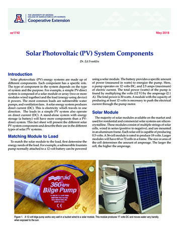
3.1.4How Photovoltaic Systems Work, and Associated Safety and Testing IssuesBoth the modules and inverters in PV systems are subject to UL standards, however this only provides a measure of safetyof the device and does not indicate field performance or reliability. There are relatively few resources to findcomprehensive and unbiased analyses on field performance of these products. And even so, a given product may performquite well in one set of conditions but under-perform in other conditions (e.g. at given temperatures, voltages, etc.). Also,manufacturer specifications are listed in a laboratory and it is important to recognize that field performance is far moredynamic than what is seen on a specification sheet.For modules, the tolerance of the manufacturing processes (i.e. modules rated as a given number of Watts /- X%) is onekey parameter. Likewise, the performance in the temperature conditions expected at your site will be relevant. Modules alsoachieve a lower performance due to voltage degradation over time, so understanding the stability of the products is valuablein determining the long-term system output. Meanwhile, system designers should also consider other issues like how wellmodules endure various environmental effects.Inverters are also complex components. Inverter performance and reliability is important to good system design, since itenhances or limits the effectiveness of a given system. Inverters have many more variables than modules. Although DCAC conversion efficiency is often the primary factor looked at to determine system performance, this alone is incompleteand can be misleading since this efficiency changes with DC input voltage, AC output voltage, percentage of load, andseveral other factors. The output of a system is also dictated by its maximum power point tracking effectiveness, its abilityto output high power at the site's expected temperature, and product reliability. The most critical objective of any inverter isto output kWh throughout the life of the system. Choices should typically be based around this principle, and then the otherfeatures of the products.Warranties, manufacturer reputability, and ease of installation/use are also worth considering for both modules andinverters. As with any other type of products, there are a wide array of manufacturers offering a range of performance,reliability and features. Discussions with other experienced installers is often the most effective way of determining aproduct's true value in the field. For example, some modules may be rated within /- 5%, but often perform at the lower endof this tolerance while others with the same tolerance may regularly achieve their output target, or even above. Someinverters offer sophisticated self-diagnostic systems to assist installers in servicing systems or data monitoring systems thatallow installers or end-users to view performance more easily over a computer. Though looking at specification sheets andproduct literature is often a good place to begin your search for choosing the appropriate components for a system, it is bestto get input from experienced users on the products you may specify prior to installing them.3.1.4.1Photovoltaic ModulesPhotovoltaic modules generate electricity as a result of sunlight shining on the PV cells, and these cells may be made of anyof several technologies. Some of these technologies used in flat-plate modules (as opposed to concentrator modules)include crystalline silicon cells, multi-crystalline silicon cells, thin-film amorphous silicon cells deposited on a substrate,thin-film cadmium-telluride (CdTe) cells deposited on glass or other suitable substrate, thin-film copper-indium-diselenide(sometimes referred to as CIS) deposited on glass or other suitable substrate, or other technologies now being developed.Using crystalline technology for example, where individual cells produce dc voltages of approximately 0.5 volt and dccurrents in the range of one to eight amps (with the amperage depending on the surface area of the cell) takes a largenumber of cells to produce appreciable amounts of voltage and power. Usually, PV cells are grouped into series strings of36 or 72 cells to produce open-circuit voltages of approximately 20 or 40 V, though these configurations change withmanufacturing trends. A 120-watt PV module made of crystalline silicon PV cells encapsulated between layers of glass,antireflective coating, and an encapsulant material in an aluminum frame will typically have an area of about 10 ft2, andwill weigh about 30 pounds. Each year, however, sizes of PV modules have been increasing. During the decade of the1990s, most modules produced were in the 35 to 75 watt range, while modules are now common in the 100-200 watt range,with some producing as much as 300 watts and weighing more than 100 pounds.Study Guide for the Applicant for NABCEP Photovoltaic Installer CertificationVersion 3 – August, 20056
Other technologies require multiple cells in series and parallel, resulting in different voltage and current characteristics forthe modules. Temperature coefficients for voltage and current output as well as conversion efficiencies differ for eachtechnology.Photovoltaic module performance is characterized by its open circuit voltage (Voc), short circuit current (Isc), maximumpower voltage (Vmp), and maximum power current (Imp). Figure 1 shows a typical relationship between module current andmodule voltage for different levels of sunlight (irradiance) incident on a PV module.Sunlight intensity is called Irradiance, which is measured in watts per square meter (W/m2). In summer, when the sun isnearly directly overhead, its irradiance at the surface of the Earth, at sea level, is approximately 1000 W/m2. Thisirradiance is defined as “full” or “peak sun,” and it is the standard irradiance for testing and rating PV modules. At
Study Guide for the Applicant for NABCEP Photovoltaic Installer Certification Version 3 – August, 2005 1 1. Introduction This Study Guide presents some of the basic cognitive material that individuals who install and maintain photovoltaic (PV) File Size: 833KB