Transcription
Standard for Installing andMaintaining Photovoltaic(PV) Power SystemsPresented by:Gregory W. Massey, P. E.OverviewNECA 412, Standard for Installing and MaintainingPhotovoltaic (PV) Power SystemsNECA 412 is currently in the ANSI approval processWhat are NEIS NEIS - National Electrical Installation StandardsA series of installation manuals for electrical products andsystemsLevels the playing field by establishing minimum qualitystandards for installing equipment and systems1
National ElectricalInstallation Standards NEIS Describe installation practices that go beyond theminimum safety requirements found in the NEC Ensure that electrical installation practices live up toexpected professional electrical design and installationintegrity.Approved by the American National StandardsInstitute (ANSI)NECA 412-201XNECA 412, Standard for Installingand Maintaining Photovoltaic (PV)Power SystemsOutlines the NEC requirementsfor PV Power SystemsProvides guidance in selecting,sizing, and installing PVequipment and systemsScopeIncludes the installation of low-voltage AC and DCphotovoltaic power systems, rated 1000V and less, forgrid-connected and stand-alone operation for residential,commercial, and industrial applicationsExcludes solar heating systems and PV systems ratedmore than 1000V2
ScopeConforms to NFPA 70, National Electrical Code, NFPA 70E,Standard for Electrical Safety, and other NEISpublicationsProvides recommendations, rules of thumb, and tricks ofthe tradeDefinitionsSolar cell. The basic photovoltaic device that generateselectricity when exposed to light.This is the fundamental building block for PV powersystems.Solar cells generate a DC voltage when exposed to sunlight.DefinitionsPV Module. A complete, environmentally protected unitconsisting of solar cells, optics, and other components,exclusive of tracker, designed to generate dc power whenexposed to sunlight.PV modules (or solar panels) are the smallest commerciallyavailable PV power system component.3
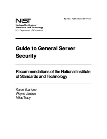
DefinitionsPV Array. A mechanically integrated assembly of modulesor panels with a support structure and foundation, tracker,and other components as required, installed as a system toform a direct current power-producing unit.Solar modules are connected in series and parallel to createan array. The PV array includes the balance of mechanicalcomponents and the balance of electrical components tomount and interconnect the solar modules.DefinitionsRoof-mountedPV arrayI-Stock photocourtesy ofNECADefinitionsSolar modules are connected in series to increase thevoltage of the array. A string of (10) solar modules with anominal voltage rating of 28Vdc would have a nominalvoltage rating of 280Vdc.Solar modules are connected in series to increase thecurrent of the array. An array of (4) strings of (10) solarmodules from the above example with a current rating of3.5A each would create a nominal 280Vdc array with acurrent rating of 14.0A.4
DefinitionsPhotovoltaic Output Circuit. Circuit conductors betweenthe photovoltaic source circuit(s) and the inverter or DCutilization equipment.The DC utilization equipment can be DC loads or energystorage battery charging equipmentDefinitionsPhotovoltaic Power Source. An array or aggregate ofarrays that generates DC power at system voltage andcurrent.DefinitionsPhotovoltaic Source Circuit. Circuits between modulesand from modules to the common connection point(s) of theDC system.Strings of modules are connected together at a “combinerbox” (common connection point) that has overcurrentprotection, frequently fuses, and blocking diodes thatprevent current from flowing into a fault within the array.5
DefinitionsInverter. Equipment that is used to change voltage level orwaveform, or both, of electrical energy. Commonly, aninverter [also known as a power conditioning unit (PCU) orpower conversion system (PCS)] is a device that changes dcinput to an ac output. Inverters may also function as batterychargers that use alternating current from another sourceand convert it into direct current for charging batteries.DefinitionsAn inverter is required to convert DC power generated bythe typical PV array into AC power suitable to directly supplytypical utilization equipment or compatible with the electricutility grid when grid-connected and part of a utilityinteractive distribution generation system.6
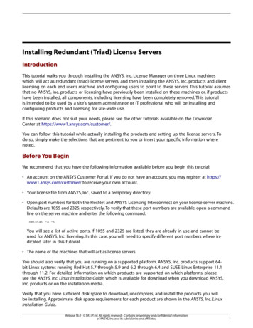
DefinitionsInverters connected in aPV power systemPhoto courtesy of CentralFlorida Electrical JATCDefinitionsAlternating-Current (AC) Module (AlternatingCurrent Photovoltaic Module). A complete,environmentally protected unit consisting of solar cells,optics, inverter, and other components, exclusive of tracker,designed to generate AC power when exposed to sunlight.AC PV modules have an integral inverter and generate ACpower. The output of an AC PV module is considered to bethe output of an inverter in applying NEC requirements.DefinitionsInverter Input Circuit. Conductors between the inverterand the battery in stand-alone systems or the conductorsbetween the inverter and the photovoltaic output circuits forelectrical production and distribution network.The inverter input circuit can also be PV output circuit.7
DefinitionsInverter Output Circuit. Conductors between the inverterand an AC panelboard for stand-alone systems or theconductors between the inverter and the service equipmentor another electric power production source, such as autility, for electrical production and distribution network.DefinitionsUtility-interactive inverter. An inverter intended for usein parallel operation with an electric utility to supplycommon loads that may deliver power to the utility.A utility-interactive inverter contains protection, monitoring,and controls that enable the PV array to operate in parallelwith the electric utility grid.DefinitionsInverter controls. Controls that regulate power conversionfrom DC to AC, synchronize to the electric utility grid,monitor bus voltage and frequency, and provide protectionin the event of a fault, failure, or abnormal operatingcondition.Synchronization. Process of matching the operatingvoltage, frequency, and phase angle of one source toanother source prior to paralleling the sources together.8
DefinitionsInteractive System. A solar photovoltaic system thatoperates in parallel with and may deliver power to anelectrical production and distribution network. For thepurpose of this definition, an energy storage subsystem of asolar photovoltaic system, such as a battery, is not anotherelectrical production source.AKA – grid-connected or operating in parallel with theelectric utility gridDefinitionsElectrical Production and Distribution Network. Apower production, distribution, and utilization system, suchas a utility system and connected loads, that is external toand not controlled by the photovoltaic power system.AKA – the electric utility gridDefinitionsNet metering. Utility billing practice that permits powerdelivery from distributed generation sources to the electricutility grid across the utility revenue meter.Frequently, net metering does not entail a direct paymentfrom the electric utility company to the customer, but acredit for power generated in excess of power consumed onsite. This credit typically expires within a contractual timeperiod.9
DefinitionsPower buy-back. Utility purchase of excess power fromcustomer-owned distributed generationAgreement between the electric utility company and thecustomer to purchase excess power from customer-owneddistributed generation. Typically used for relatively largescale customer-owned generation, which may be 1,000kWor more.DefinitionsStand-Alone System. A solar photovoltaic system thatsupplies power independently of an electrical production anddistribution network.A stand-alone PV system operates independently of theelectric utility grid. During times when a PV array is notgenerating power, such as at night, a stand-alone PV powersystem must have either one or more alternative powergeneration methods (Hybrid System) or energy storagebatteries.DefinitionsHybrid System. A system comprised of multiple powersources. These power sources may include photovoltaic,wind, micro-hydro generators, engine-driven generators,and others, but do not include electrical production anddistribution network systems. Energy storage systems, suchas batteries, do not constitute a power source for thepurpose of this definition.Alternatively, a stand-alone PV system can use energystorage batteries, which require additional equipment andcontrols for battery charging.10
DefinitionsBattery Charger. A device that can maintain aunidirectional current in a battery in the opposite direction tothat during discharge thereby converting electric energy intostored chemical energy within the battery.Charge Controller. Equipment that controls DC voltage orDC current, or both, used to charge a battery.DefinitionsDiversion Charge Controller. Equipment that regulatesthe charging process of a battery by diverting power fromenergy storage to direct-current or alternating-current loadsor to an interconnected utility service.Protects batteries from overcharging by diverting power to anon-essential DC load, such as lighting.11
DefinitionsInsolation. The average solar energy that reaches theearth's surface at a given location per day, expressed askilowatt-hours-per-square-meter per day (kWh/m2/day).Peak Sun Hours. The equivalent measure of total solarirradiation in a day.DefinitionsSolar Irradiation. The total amount of solar energyaccumulated on an area over time, typically expressed askilowatt-hours-per-square-meter (kWh/m2). Solar irradiationis the principle measurement used to quantify solar energyproduction over time.DefinitionsTilt angle. The orientation angle of the solar array withrespect to the horizon, expressed in degrees.Incident angle. Orientation angle of the sun with respectto the horizon, expressed in degrees.12
DefinitionsAzimuth. The orientation angle of the solar array withrespect to solar south (0o) expressed in degrees. Sunposition to the east of solar south is typically represented bya positive azimuth angle, where sun position to the west ofsolar south is typically represented by a negative azimuthangle.IntroductionPV power systems convert sunlight (solar energy) intoelectric energyIndividual solar cells convert sunlight into DC voltageSolar cells are electrically and mechanically interconnectedto form solar panelsIntroductionSolar panels are connected in series and in parallel to formsolar arraysConnecting solar panels in series increases voltageConnecting solar panels in parallel increases currentVirtually any operating voltage and power rating can beachieved13
IntroductionPV output circuits from each series string are connected toan overcurrent protective device, typically fuses, andblocking diodes, in a combiner boxOne set of DC output conductors from the combiner box areconnected to the DC disconnecting meansIntroductionThe DC output conductors from the DC disconnecting meanscan be used to supply:l DC loads directlyl Energy storage batteriesl An inverter input circuit with or without batteriesEnergy storage batteries require a battery charger, chargecontroller, or diversion charge controller14
IntroductionA charger or charge controller regulates battery voltage andthe charge or discharge current and protects batteries fromdamaging voltages, currents, and temperaturesIntroductionMost often, PV power systems supply utility-interactiveinverters, are grid-connected, and supply AC loadsInverters convert DC voltage into an AC waveform that iscompatible with AC loadsUtility-interactive inverters are used to connect solar arraysto the electric utility grid15
IntroductionUtility-interactive inverters:l Control the power transfer from the PV array to AC loadsand/or electric utility gridl Protect the PV array from the electric utility gridl Protect the electric utility grid from the PV arrayIntroductionUtility-interactive inverters monitor the electric utility grid toensure the one-way transfer of power from the PV array tothe connected loads and/or to the electric utility gridIntroductionStand-alone PV power systems (that operate independentlyof the electric utility grid) must have either energy storagebatteries or one or more alternative power generationsources, or both, to supply power to loads when solar poweris not available, such as at night16
PV System OperationPower output from a PV power system follows a Bell curve,with the greatest output on a bright, sunny day with lowambient temperaturePV power output drops off with sunlight intensity and withtemperaturePV System OperationPV power output is affected by:l Atmospheric conditionsl Ambient temperaturel Ground snow coverPV System OperationSolar PV power systems are a “passive” generationtechnologyOnly produce power when exposed to sunlightCannot store electricity for later use unless equipped withenergy storage batteries17
PV System OperationGrid-connected systems only produce power when theelectric utility grid is operationalCannot increase power output in response to an increase inloadCannot predict PV power generation at any given point intimePV System OperationCan accurate predict PV power generation over time basedon the local solar resourceInsolation is the average solar energy density at a givenlocation, expressed as kilowatt-hours per square meter perday (kWh/m2/day)Insolation data is used to calculate the average annual PVenergy output of a given PV arrayPre-Installation ConsiderationsElectrical Contractor Responsibilitiesl Communication with manufacturers, vendors, suppliers,utility, owner, inspector, othersl Understand the types of PV systems and which type is tobe installedl Perform and accurate efficient site assessment of existingpower service18
Pre-Installation ConsiderationsElectrical Contractor Responsibilitiesl Provide accurate and clear estimate of necessaryupgrades (if applicable)l Coordinate with the local electric utility company andAuthority Having Jurisdiction (AHJ)l Use expertise to ensure a positive customer experiencePre-Installation ConsiderationsThe Electrical Permit Processl Determine and contact the applicable AHJl Determine the applicable NEC edition and other Codesadopted and enforced by the AHJl Verify if there are specific local amendments to the NECrulesPre-Installation ConsiderationsThe Electrical Permit Processl Verify the specific installation procedures and processesl Verify utility company requirements–––Separate revenue meter is requiredDifferent rate tariff appliesApplication forms and fees are required19
Pre-Installation ConsiderationsThe Role of the Inspectorl Issuing construction/installation permitsl Enforcement of the NEC and other Codes adopted withintheir jurisdictionl Review of plans and specifications for Code compliancePre-Installation ConsiderationsThe Role of the Inspectorl Conduct field inspectionsl Issuing of non-compliance reports/inspectors noticesl Notifying utility for connection or meter clearancesl Issue approvals upon completion of projectPre-Installation ConsiderationsElectrical Inspection Processl Coordinate and schedule the rough-in and finalinspectionsl NECA recommends setting up an on-site inspectionmeeting to assist the inspector and to directly addressany issues or concerns to expedite the inspection processl Address all deficiencies that are identified by theinspectorl Maintain records of the inspection and approval process20
Pre-Installation ConsiderationsEnvironmental considerations:l PV modules are relatively immune to rain, snow, sleetand haill PV power output increases with elevationl PV power output decreases with temperaturePre-Installation ConsiderationsBuilding Codes, fire codes, and zoning requirementsl Firefighter safetyl Solar panel layout and arrangementl Access to disconnecting meansl Overcurrent protectionl Safety and warning labelsPre-Installation ConsiderationsPermitsl New PV systems on new structuresl New PV systems on existing structuresSubmittalsl Greater than 5kWl Residential system that occupies more than 50% of theroof area21
Pre-Installation ConsiderationsSubmittals – plan requirements:l Plans with locations and one-line diagrams withconnectionsl Equipment data, sizing, ratings, Listing information andapprovalsl Equipment locations and laying with clearances, pathways,and access informationPre-Installation ConsiderationsUtility Interconnection Requirementsl Must comply with NEC Article 705.12 regarding the pointof connection (point of common coupling)l May require additional disconnecting means accessible toelectric utility company personnell Labeling, metering, overcurrent protection, automaticdisconnectionl Forms, fees, permitsPre-Installation ConsiderationsLocating PV arraysl Full sun exposurel No obstructions, shadingl Generally oriented toward solar southl Can orient slightly east or west, but not northl Roof-top installations – must meet access and requiredclearances for firefighting, smoke ventilation, etc.22
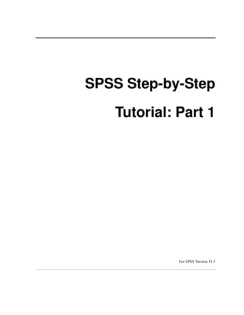
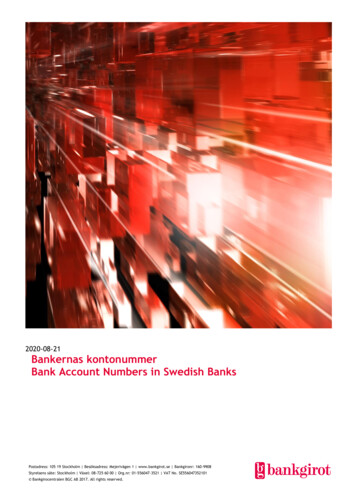
Pre-Installation ConsiderationsMounting optionsl Fixed mounted (flush-mounted, typically on a roof,mounted on a static, tilt-up support structure, or pole-topmount)l One-axis or two-axis tracking (specialized pole-topmount)Pre-Installation ConsiderationsFlush roof-mountedPhoto Courtesy ofNEC, CopyrightRob ColganPre-Installation ConsiderationsStructural supportFrameworkPhoto Courtesy ofCentral FloridaElectrical JATC23
Pre-Installation ConsiderationsTracking Array(Pole-top)Photo Courtesy ofIBEW Local 26Electrical JATCTraining CenterPre-Installation ConsiderationsTracking Arraysl Rotate from east to west to follow the path of the sunl Two-axis tracking adjusts tilt-anglel Incremental increase in PV energy productionl Increased maintenance and repair costs (moving parts)l Increased installation costsPre-Installation ConsiderationsRoof-top Considerationsl Crimp or cover sharp edges of PV equipment, components,fastener tipsl Pathways that cross conduits, pipes, braces, etc., must beclearly marked in red/white reflective tape or other FDapproved identifying materiall Items higher than 18” typically must have steps up anddown on either sidel Establish pathways during design24
Pre-Installation ConsiderationsAccess and Required Clearancesl Residential Buildings––Hip Roofs – provide (1) 36” wide clear access path from theeave to the ridge on each roof slope with PV panelsSingle Ridge – provide (2) 36” wide access pathways from theeave to the ridge on each roof slope with PV panelsPre-Installation ConsiderationsAccess and Required Clearancesl Residential Buildings––Hips and Valleys – 18” required clearance on both sides if bothsides have PV panels; if PV panels are installed on only one sideif of equal length, panels can be placed directly adjacent to thehip or valleyLocate pathways at a structurally supported location, such as ata load bearing wallPre-Installation ConsiderationsAccess and Required Clearancesl Commercial Buildings and Residential Housing of Three orMore Units–––––Minimum 48” wide clear perimeter around the edges of the roofLocate pathways over structural membersProvide centerline axis pathways in both axes of the roofProvide straight-line pathways not less than 48” wide to skylightsand/or ventilation hatchesProvide straight-line pathways not less than 48” wide to roofmounted standpipes25
Pre-Installation ConsiderationsAccess and Required Clearancesl Commercial Buildings and Residential Housing of Three orMore Units––Provide 48” minimum clearance around roof access hatches witha minimum of (1) 48” wide pathway to the parapet or roof edgeArrays must be no greater than 150ʼ in length in any direction topermit smoke ventilationPre-Installation ConsiderationsAccess and Required Clearancesl Commercial Buildings and Residential Housing of Three orMore Units–For smoke ventilation, provide a minimum 96” wide pathwaybetween arrays, a minimum 48” wide pathway that borders roofskylights or ventilation hatches, or a minimum 48” wide pathwaybordering 48” by 96” venting cutouts every 20ʼ on alternatingsides of the pathwayPre-Installation ConsiderationsStructural Systemsl Flush-mounted roof-topl Universal tilt-up structural support (roof-mounted orground-mounted)l Pole-mounted (static)l Tracking array26
Pre-Installation ConsiderationsRoof Mountingl Most likely to be flush-mounted (in the same plane asthe roof and less conspicuous than tilt-up structuralframework)l Least expensive, most simple installationl Self-ballasted systems do not require attachment to theroof.Pre-Installation ConsiderationsRoof Mountingl Metal brackets installed on each solar panel and securedto the roof or low-profile mounting rails (to provide aircirculation)l Use stainless steel bolts and hardware, or J-boltsl When possible, install the PV array during the installationof the roof. Otherwise, employ qualified roofingcontractor to patch/repair mounting holes usingapproved materials and methods to maintain anywarranties.Pre-Installation ConsiderationsRoof Mountingl Flush-mounting offers no flexibility in solar arrayorientationl Typically used for smaller PV power systems27
Pre-Installation ConsiderationsUniversal Tilt-Up Structural Supportl Can be roof-mounted or ground-mountedl Typically non-moving (or static)l Used for larger solar arraysPre-Installation ConsiderationsUniversal Tilt-Up Structural Supportl When roof-mounted:––––l More expensive than flush-mountedIncrease wind resistanceTypically present a challenge with local building codesProvide flexibility with orientation and tilt-angleMore likely to be ground-mountedPre-Installation ConsiderationsPole-Top Mountingl PV array can be mounted to a structural frameworkbolted to a sleeve and set on a pole embedded inconcrete or earthl Can be heavyl Can increase wind resistance28
Pre-Installation ConsiderationsTracking Arrayl Specialized pole-top mountingl PV array can rotate on the mounting pole (one-axistracking) and may also contain controls to control thetilt-angle of the support structure (two-axis tracking)l Active tracking has motorize controls to adjust east-towest array orientationPre-Installation ConsiderationsTracking Arrayl Passive tracking has sealed tanks on each side withinterconnecting tubes and a liquid medium that rotatesthe array with no motors, gears, or exterior controlsl Tracking arrays increase PF power production byorienting the array more directly towards the sun duringdaylight hoursPre-Installation ConsiderationsPV Power System Configuration:l Utility interactive systeml Stand-alone systeml Bimodal systeml Hybrid systeml Direct-coupled system29
Pre-Installation ConsiderationsUtility-Interactive Systems (more common):l Operate in parallel with the electric utility gridl Utility-interactive inverter (control and protection) mustbe Listedl Inverter monitors utility voltage and frequency and onlydelivers power when the utility is stablel Sizing of the PV array is less critical as the electric utilitygrid acts as a buffer - ExamplePre-Installation ConsiderationsPV Power System Performance Estimate (also see Annex A)l Cannot predict PV power generation at any given point intimel Can accurately estimate PV power generation over timePAEO 365(IPSH)(PSAR)(0.77)Pre-Installation ConsiderationsPV Power System Performance Estimate (also see Annex A)How do we find IPSH?http://rredc.nrel.gov/solar/old data/nsrdb/30
Pre-Installation ConsiderationsContains the 30-year average of monthly insolation datafrom 1961 through 1990 for select cities throughout theUnited States, and has an update for data from 1991through 2005Data tables found on this website include insolation data forvarious types of solar panels (flat plat and concentratingcollectors) and mounting methods (fixed, one-axis tracking,and two-axis tracking)Pre-Installation ConsiderationsMust consider tilt-angle of the array. Typically, tilt-angle isset to site-latitude to maximize year-round PV energyproduction. PV arrays can be tilted more vertically toincrease PV power generation during winter months (sunlow in the sky) or more horizontally to increase PV powergeneration during summer months (sun higher in the sky).Tilt-angle can also be adjusted periodically, such asquarterly, to maintain more optimal orientation towards thesun during the seasons.Pre-Installation ConsiderationsSizing Example:For a non-tracking (static) flat-collector PV panels orientedtowards solar south at site latitude (to maximize year-roundPV energy production) located in San Diego, CA, the yearround average IPSH is 5.9 peak sun hours per day.31
Pre-Installation ConsiderationsSizing Example:Plugging in to our formula gives:PAEO 365(5.9)(PSAR)(0.77) (1658)(PSAR)Meaning that for every 1.0 kW of output power rating, a PVarray will generate approximately 1,658 kWh of energy peryear.Pre-Installation ConsiderationsThis information can be used to determine the PV energyproduction of a given-sized PV array, or the minimum-sizedarray needed to generate a given quantity of energy.For example, a 3.5kW array will generate approximately5,803 kWh per year.PAEO (1658)(3.5) 5,803 kWhPre-Installation ConsiderationsAdditionally, the minimum-sized array needed to generate20,000 kWh per year is 12.063 kW:PSAR (20,000)/(1658) 12.063 kW32
Pre-Installation ConsiderationsChanging any of the variables (location, tilt-angle, type ofsolar panel, static vs. tracking, etc) would change expectedpower productionPre-Installation ConsiderationsNet Metering:l Common utility revenue meterl Monitors two-way power transferl When on-site power generation exceeds the on-siteconnected load, power is delivered to the electric utilitygridl When on-site connected load exceeds on-site powergeneration, power is delivered from the electric utilitygridPre-Installation ConsiderationsNet Metering:l Utility billing is based on the net difference betweenpower delivered to the electric utility grid and powerdelivered to the customer from the electric utility gridl The customer is charged or credited for the net flow ofenergy across the utility revenue meterl Net metering agreements rarely have provisions fordirect utility payments for any credits33
Pre-Installation ConsiderationsNet Metering:l Net metering agreements typically provide a credit forcustomer power generation in excess of on-siteconnected loadsl Such credits typically expire after a contractuallyspecified time periodl When net metering is not offered, it may be necessary toinstall a separate utility revenue meter for on-site powergenerationPre-Installation ConsiderationsDual Metering:l PV systems are connected to the electric utility gridthrough a separate meterl Frequently used for large-scale PV systemsl Provides the ability to use different tariffs for the value ofenergySafetyGeneral:l PV panels generate voltage when exposed to sunlightl High open-circuit voltagel High voltage during low ambient temperaturel High temperature inverter operationl Multiple sources of power has the potential for backfeedsthroughout the systeml Energy storage batteries34
InstallationGeneral:l Review installation instructionsl Install PV equipment in accordance with the listinginstallation instructionsl PV power system equipment must be identified andListed for the purposel Comply with all warning and safety labelInstallationGeneral:l Check physical dimensionsl Identify where equipment will be installedl Check existing panels for sufficient space and capacity toconnect PV power systemsInstallationArrays:l Develop a preliminary sketch of where solar panels willbe installedl Resolve conflicts prior to installation, giving precedenceto systems or equipment with a required slope orclearancel Install away from equipment that will shade panels35
InstallationArrays:l Ensure adequate access and pathways around arraysl Check that the array open circuit voltage does notexceed the voltage rating of invertersl Adjust the tilt angle to suit project requirements, such asbiasing to increase winter energy production or summerenergy productionInstallationInverters and Charge Controllers:l Verify that the total current and power of the array iswithin the ratings of the inverter. Additional invertersmay be required to meet the power capacityrequirementsl Inverter and charge controller operation is greatlyinfluenced by ambient temperature, airflow, exposure tosunlight, input voltage, input power and orientation ofthe heatsink finsInstallationInverters and Charge Controllers:l Locate inverters away from sources of heat, such as highambient temperature, sunlight, etc., and ensure adequateclearance and proper airflowl Observe the manufacturerʼs instructions for the mountingorientation, and derate inverters for mounting orientationother than verticall Mount inverters and charge controllers before terminatingconductors36
InstallationInverters and Charge Controllers:l Check that the PV source circuit impedance is within theinverter manufacturerʼs recommended tolerancesl Internal components may be energized and uninsulated,may move or rotate, and may be hot to the tough. Do nottouch internal or external inverter or charge controllercomponents during operationInstallationInverters and Charge Controllers:l Connect inverters and charge controllers to the electricalpower distribution system only after receivingauthorization from the load electrical utility providerInstallationDisconnecting Means:l Provide disconnecting means to disconnect all currentcarrying DC conductors of the PV power system,including inverters, batteries, charge controllers, etc. Adisconnecting means is not required at the PV module orarray locationl Group and identify disconnecting means for equipmentenergized from more than one source37
InstallationDisconnecting Mean
Conforms to NFPA 70, National Electrical Code, NFPA 70E, Standard for Electrical Safety, and other NEIS publications Provides recommendations, rules of thumb, and tricks of the trade Definitions Solar cell. The basic photovoltaic device that generates electricity when exposed to light. Thi